Here is the design theory behind this popular low-cost DIY kit.
By Jim Hagerman
Burning-in cables, amplifiers, and other audio equipment has long been a subject of debate.
This article does not argue the pros and cons of such a discussion, but confidently assumes both mechanical and electrical components benefit from such a break-in period. Indeed, on many occasions I have witnessed improvements firsthand.
You might ask what type of signal is best suited for burn-in. Music is one obvious candidate, but what type: vocals, percussion, organ, or rock-and-roll? Clearly, a full-range signal containing both high and low frequencies is desirable, particularly one with transient in formation. The signal should exercise and stress the entire audio spectrum.
There are now several CDs on the market containing a variety of burn-in signals, typically consisting of swept sine and square waves. This article presents an alternative hardware solution.
DESIGN GOALS
The FryKleaner was designed to be a complete self-contained burn-in system.
Included on the deceptively small circuit board is a very sophisticated wave form generator and built-in power amplifiers capable of directly driving cables. A wall-wart supplies power.
My design goals were simple: a do-it yourself kit using all-analog circuitry implemented with low-cost vintage bipolar integrated circuits. Certainly, a microprocessor or software realization was possible, but this was a more interesting and practical challenge. Additionally, all parts should be readily available from a single source, and construction should be simple and straight forward.
THE WAVEFORM
First, I needed to produce a waveform containing all of the previously mentioned properties. Design work on one of my recent consulting projects (broad band modem for undersea instrumentation) employed two very useful circuits: a wideband noise source, and, an amplitude modulator. In fact, familiarity with these circuits is what spawned the idea to make a burn-in generator.
What better way to mimic a wideband music signal than with a noise source? Such a circuit generates all frequencies at equal amplitudes at the same time.
That is, a plot of the frequency spectrum would be a flat horizontal line.
If viewed on an oscilloscope, the amplitude would be purely random with an average of zero--very much musical in appearance. For burn-in purposes, this signal covers low bass frequencies all the way up to the highest treble without emphasis on any particular band. Nevertheless, there is room for improvement.
A continuous noise signal would present a rather benign and constant load to an amplifier under burn and its power supply. Gating the noise source on and off would introduce varying thermal and current loads, thus exercising and stressing the amplifier more fully. To this end, the noise source could be amplitude modulated by a low frequency signal, preferably a sine wave, which would prevent excessive switching transients (Fig. 1).
However, this, too, should not be done at a constant frequency. No particular frequency should be emphasized or eliminated; the modulation is best swept over a range. Most important, it should delve deep into infrasonic territory exerting strain on the power supply and any low-frequency system resonance.
CIRCUIT AND OPERATION
Starting backwards from the output, U1 and U2 (Fig. 2) are small power amplifiers in convenient 8-pin DIP packages capable of delivering a bit of output power. Typically, the output signal is a line-level voltage used to drive the input of an amplifier. However, when directly driving cables, power amplifiers are needed to deliver the required current, as a cable presents a short circuit for a load. The 100 -ohm series resistors (e.g., R2) serve as current limiters. Amplifiers are connected in opposite polarity so balanced cables can be driven differentially.
---------------------------
ABOUT THE AUTHOR
Jim Hagerman owns Hagerman Technology LLC, a supplier of unique DIY half-kits and high-end audio products. He's been designing analog circuits for 20 years.
------------------------
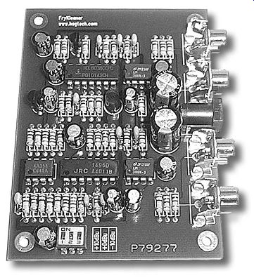
PHOTO 1: The FryKleaner board has a very clean and orderly layout, making
it easy to assemble.
Cables can be burned-in using either voltage or current. Voltage mode is achieved by leaving one end of the cable disconnected. This is often a rather ineffective method, because without a current draw the magnetic properties of the conductors are not exercised. Shorting one end of the cable will generate a current flow and force the voltage to zero.
The FryKleaner's maximum output signal level of +10dBu (2.5V) produces 25mA through the cable, far greater than experienced under normal audio use. A cable can be conveniently connected between output amplifiers for the same effect.
The input to the power amplifiers comes from the modulator U4, which is really just an analog multiplier based on a Gilbert cell. These ICs were commonly used in AM radio circuits, in which an audio signal was multiplied by an RF carrier. I used it here to multi ply the noise source with the swept sine wave. The multiplication process acts as a volume control for the noise source, whereas the envelope of the amplitude follows the absolute value of the low-frequency sine wave.
Gain is adjusted by changing the value of a single resistor. Switches select the three output levels of 0.25V, 0.78V (0dBu line level), and 2.5V.
There are many ways to generate a wideband noise signal. A lengthy pseudo-random bit sequence is a popular choice and can be very well con trolled. One all-analog method uses a PN junction operated in avalanche breakdown mode--a zener diode. Normally implemented as voltage refer ences, they must be bypassed with capacitance for quiet operation.
Q1 is operated as a zener diode by driving its base-emitter junction into re verse breakdown. The R1-C2 low-pass filter removes any residual 120Hz power supply noise from getting into this sensitive circuit. U3B provides about 40dB of AC gain and a DC bias level for driving the carrier port of the modulator. One side benefit of the carrier port is that it also acts as a limiter, removing any excessive and rare noise spikes.
The sine-wave generator is based on the very clever 8038, which converts a triangle waveform into a reasonably low distortion sine wave via a ladder of diode clamps. Frequency sweeping is accomplished by changing the bias voltage on pin 9, with Q2 acting as an appropriate level shifter for the output from the ramp generator. The frequency range is programmed at 2Hz to 200Hz, covering the infrasonic and bass regions of audio. LED D1 is driven in sync with the sine wave to provide an indication of operation.
The U3A op amp is operated as a comparator in the ramp generator circuit.
Fortunately, the LM358 does not have input clamp diodes and can function in this mode. By using positive feedback and hysteresis, the circuit charges C15 from 4V to 8V and back again, producing a very slow triangle waveform. The period lasts about 20 seconds.
Simple RC networks are used as power filters for ripple rejection from the wall-wart's relatively dirty supply. Separate filters disconnect any unwanted feedback from the output amplifiers into the sensitive waveform generator circuits. The series resistors in the filters also act to drop voltage in an attempt to tune outputs to exactly 12V.
CONSTRUCTION
The FryKleaner circuit has been care fully laid out on a small circuit board (Photo 1). I chose parts for their practicality, low cost, and ease of assembly.
Construction is quite simple and any one who can solder can do it in under an hour.
FryKleaner can optionally be constructed within a chassis. Instead of mounting connectors and switches on the circuit board, you can panel-mount them to the chassis and link them via wires. This accommodates use of alternate connectors such as XLR or binding posts. It also makes for a more ro bust product.
RESOURCES
A high-quality circuit board and plans are available from the author at www.fryKleaner.com. You can obtain all remaining parts from Jameco Electronics at www.jameco.com. ?
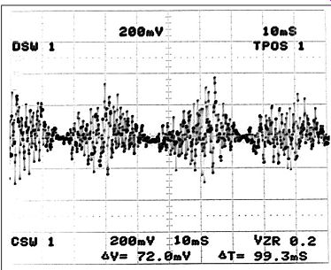
FIGURE 1: Oscilloscope trace of waveform shows noise source modulated
by low-frequency sine wave.
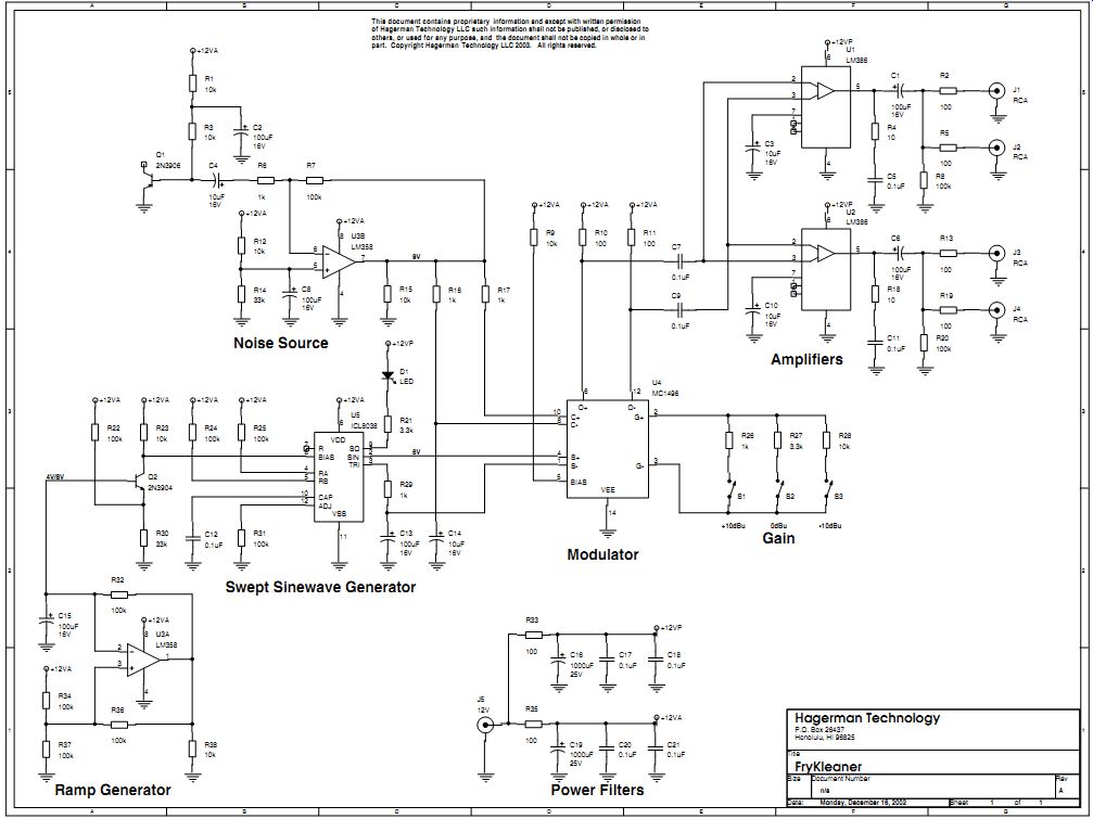
FIGURE 2: Schematic of FryKleaner.
------------------
Also see: AGAINST THE WALL: AN UPGRADE