The author describes an improved treble speaker, and provides details on its electrical and acoustic design and mechanical construction.
By John Mattern
This new treble speaker (compatible with the bass speaker de scribed in aX Dec. 2002, p. 24) uses a separate midrange and tweeter to replace the original coaxial design, each providing high-end performance. It uses a short transmission line within the midrange enclosure and a cascaded first-order crossover (CO).
Axial offset of the tweeter provides for precise alignment at the listener's position. I replaced the stepped diffraction wings of the original speaker design with sloping wings without altering the original bass enclosure (Photo 1). This article includes details for calculating the tweeter offset, as well as a description of the testing environment and test results.
CHOICE OF DRIVERS
I chose the Audax 4” carbon fiber mid bass for the midrange driver and a Vifa 1” tweeter with ferrofluid cooling and a double chamber to provide treble response. The Audax provides ample overlap with the bass driver and adequate overlap with the tweeter at the other end to allow use of a first-order CO design. Sufficient overlap at the top end is made possible by the low-end ex-tension achieved by the Vifa tweeter.
The two crossovers are 1kHz and 4kHz.
This combination handles consider ably more power than the previous treble unit, and at the listener level has a much smoother response than the earlier coaxial design. Also, the cascaded first-order CO provides more protection for the tweeter than a two-way first order CO would. It is more expensive to build, however.
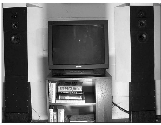
PHOTO 1: Upgraded stereo system flanking the TV in my club room.
TABLE 2
OPTIMUM LISTENING HEIGHT VS. DISTANCE FROM SPEAKER DISTANCE FROM SPEAKER (FT) DISTANCE ABOVE FLOOR (IN)
1.0 51.29 2.0 50.64 3.0 50.00 4.0 49.36 5.0 48.71 6.0 48.07 7.0 47.43 8.0 46.78 9.0 46.14 10.0 45.50 11.0 44.85 12.0 44.21
First-order CO: Normal Polarity
Measured value of H = 50 ” at D = 36 ” for phase match at 4kHz without CO computed axial offset (in) = 0.2614.
ELECTRICAL DESIGN OF THE CROSSOVER
The cascaded first order is easy to implement and realize. Figure 1 shows the electrical schematic for the new CO.
The enclosed area in the figure is the treble component of the complete speaker system. Its two drivers are by-passed by Zobels to flatten the impedance characteristics. I used resistance and capacity decade boxes together with the Liberty Instruments IMP to optimize the Zobels.
Table 1 provides the calculations I used for the Audax and Vifa drivers. Capacitor C5 and inductor L2 form a first order CO at a 4kHz crossover for a 7.5” system. Figure 2 shows the impedance of the finished treble speaker, which looks very much like that of a single speaker and is treated as such when de signing the bass to midrange CO.
The only trial and error involved the padding to the 6” Vifa tweeter. Padding is required to present a 7.5” load to C5, while at the same time providing the correct attenuation. The Vifa tweeter is more efficient than the Audax drivers.
Capacitor C4 and inductor L1 form a first-order CO at 1.0kHz crossover for a 7.5” system. This works in the region above the system resonance of LS2, which is 54Hz in free air. Note that both COs are first order but that the tweeter is protected as in a second order system, except where the midrange driver is resonant. A measurement at the midrange resonant frequency demonstrated more than 60dB rejection at the tweeter terminals.
The equivalent second order system crossover frequency is 2.0kHz.
Now what I see is the best of both worlds. The cascaded CO provides greater protection for the tweeter than the usual CO design. Because it is a first-order design, it produces an "ideal" transient response with no phase reversals. I realize that claims made for the fourth-order CO state that you cannot notice the phase reversals, although the rapid phase change at crossover for the second-order CO can be detected. I don't dispute this, I am merely skeptical. I have plans for an experiment that may shed some light on this matter.
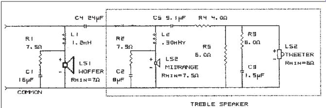
FIGURE 1: Speaker system electrical schematic--cascaded first-order
CO. B-2318-1
I must admit that I did not fully understand all the consequences of a first order CO and depended on G.R.
TABLE 1
CASCADED FIRST-ORDER CROSSOVER CALCULATIONS
FCO1 = 1.0kHz FCO2 = 4.0kHz L1 = 0.0012H R1E = RMIN + 0.24 = 7.24? F1 = 7.24/(2 * PI * L1) = 959Hz C4 = L1/(R1E 2) = 22.9µF L2 = 0.00030H R2E = RMIN + 0.36 = 7.85? F2 = 7.5/(2 * PI * L2) = 3978Hz C5 = L2/(R2E 2) = 4.86µF
Koonce to fill in the details. I am refer ring to the asymmetry that results when the midrange and treble CO outputs are in quadrature at the CO frequency. With the outputs connected in phase and the tweeter located above the midrange, there will be a dip above the position of equal acoustic path lengths. This occurs because the two sounds go farther out of phase with in creasing height.
However, in the downward direction the two sounds are more in phase, causing a broad 3dB peak. At the 90° mid point the CO action is ideal. Thus it be comes important to set the tweeter back from the midrange so that the acoustic paths are equal at the listener's position, presumably a seated one.
The same holds for the midrange and woofer pair. Here, though, the drivers are quite similar in design and size and also the frequency is much lower so the resultant vertical beam is broader and the offset is not nearly as critical. The midrange driver in the new treble speaker is set back slightly from the bass driver when their front panels are in alignment.
TWEETER AXIAL OFFSET
G.R. Koonce demonstrated in an un published paper that the first-order CO allows a wide vertical beamwidth for this driver arrangement, but with asymmetry that diminishes as the driver spacing is reduced. For this reason, I mounted the two drivers as close together as reasonable but in different planes. According to my tests this produced a below-axis alignment in time at the crossover frequency. This is desirable as the viewer is usually seated somewhat below the midrange axis.
Because there is no provision in the CO to correct the phase difference caused by the misaligned driver acoustic centers, this must be done mechanically by the enclosure front panel design. The offset consists of a 0.438” difference between the driver face plates. An offset shortfall that I am calling residual offset (RO) is needed to obtain a slight downward slope for the optimum path. I used the first formula to ...
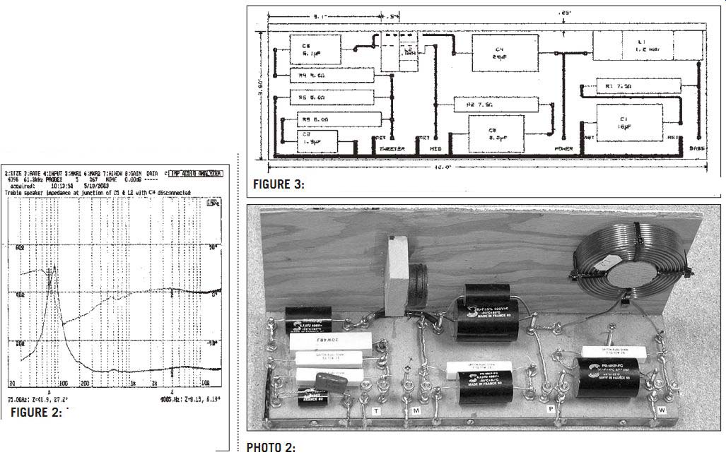
FIGURE 2: Impedance of treble speaker at junction of C5 and L2 with
C4 disconnected.
... find the RO and the second formula to find the optimum height (OH) at a given distance using RO.
RO = ( - B +v( B2 - 4 * A * C ) ) / ( 2 *A )
where: A = 1 B = 2 * D C =M2 - T2 + 2 * H * ( T -M ) and T = height of tweeter (54.38 “) M= height of midbass (49.5 “) D = distance from mike to panel (36?) H = height of mike at null (50.0?) L = distance between listener and front panel in inches.
then OH = ( RO2 + 2 * L * RO +M2 - T2 ) / 2 * (M- T ) )
If RO were 0, the optimum height would be constant. As it is, the tweeter is too far forward (RO = 0.26?), causing the optimum height to diminish with distance, a desirable condition in this case.
Unfortunately, this involved experimentation with the panel design.
Table 2 shows the result of the calculations for the final enclosure. For my viewing distance of 11' the optimum height was 45 degree, about right for the seated listener. When the dust settled, I constructed a second treble enclosure using the final panel design. The RO that I used in the treble speaker was 0.26?. The measurements that led to the numerical value of residual offset (RO) are described in the section entitled "Treble Speaker Acoustic Phase."

FIGURE 4: Treble speaker front panel assembly.
CROSSOVER CONSTRUCTION
This new CO is an extension of the one in the Dec. '02 issue. Table 3 shows the list of materials to construct the frame for the CO parts, and Table 4 shows the electrical parts list for the bass and treble speakers COs. Figure 3 shows the parts placement on the base and front panel.
I used brass screws for tie points and drilled holes for the screws before gluing the front panel to the base. This is also a good time to drill holes for the two wood screws that attach the CO assembly to the treble box. Next I inserted the flat-head brass screws from the bottom, securing them with the steel nuts.
TABLE 3
CO MECHANICAL PARTS LIST QTY. DIMENSIONS MATERIAL 1 12 × 3.5 × 0.5 ” MDF (base) 1 1.25 × 1.25 × 0.5 ” MDF (support block) 1 12 ×6.0 × 0.25 ” Plywood (panel) 29 #6/32 bolts Brass (tie points) 29 #6/32 nuts Steel
-----------
TABLE 4
SPEAKER ELECTRICAL SYSTEM PARTS LIST
PART VALUE SOURCE DESCRIPTION MFG PT# PARTS EXPRESS C1 16.0µF
Parts Express-Solen 400V Polypropylene 027-578 C2 8.2µF Parts Express-Solen 400V Polypropylene 027-564 C3 1.5µF Parts Express-Solen 400V Polypropylene 027-528 C4 24.0µF Parts Express-Solen 400V Polypropylene 027-586 C5 5.1µF Parts Express-Solen 400V Polypropylene 027-554 R1, R2 7.5 ohm Parts Express-Dayton 10W non-inductive 004-7.5 R3, R5 6.0 ohm Parts Express-Dayton 10W non-inductive 004-6.0 R4 4.7 ohm Parts Express- Dayton 10W non-inductive 004-4.7 L1 1.2mH Parts Express Air core 266-355 L2 0.30mH Parts Express Air core 260-720
*LS1 8.0” Parts Express-Audax 5.25” carbon fiber woofer HMI30CO 296-063 LS2 8.0 ” Parts Express-Audax 4.0” carbon fiber midrange HM100CO 296-053 LS3 6.0 ” Parts Express--Vifa 1.0” soft dome tweeter D27TG-35-06 264-526
*Part used in bass speaker enclosure.
--------------------
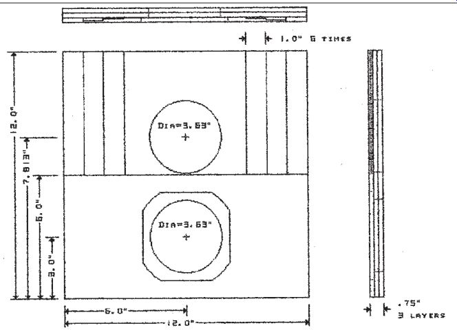
FIGURE 3: Crossover mechanical drawing.

PHOTO 2: Rear view of completed CO.
Brass nuts are preferable, but they were not available at Home Depot.
I ran a ³/8? wide copper strap on the back edge of the base to serve
as a ground bus, fastening the bus with small screws. I cut the strip
from some used copper flashing, and soldered all ground returns to
the bus and intercon nected the screws with heavy wire be fore attaching
the components. I used a heavy soldering gun to avoid cold sol der
joints. In fact, I used two guns when soldering to the copper bus.
The combi nation of heavy wire and the bus requires more than 100W.
FIGURE 4: Treble speaker front panel assembly.
I located L1 close to an upper corner and L2 in the center, both held by pieces of wood that I glued to the back of the panel. For the large coil I chose a close-fitting dowel that I fastened to the panel with glue. I glued a small rectangular block to the front panel to sup port the small coil that was held to the block with "Goop." The name of the game is to keep the coils away from anything that could affect their fields.
Once set, the coils stay put, and there are no ferrous parts or conductors near them to affect the performance.
I finished the CO by soldering the components to the ends of the brass screws. Because these components are not subject to serious vibration, I did not glue them in place. Photo 2 shows the rear surface of the CO complete with stuffing.
TREBLE ENCLOSURE CONSTRUCTION
The treble enclosure consists of a laminated front panel to which the sides and internal pieces are permanently attached with carpenter's glue. The back is attached with screws to the sides and internal pieces. The joint between the back and the connecting pieces is sealed with PVC foam weather-strip.
The internal pieces form a short transmission line (TL) that is filled with fiberglass and also provide rigidity to the completed assembly. The TL provides mechanical damping at the resonant frequency of the midrange driver that replaces some of the electrical damping lost by the first-order CO net work. Table 4 contains the parts list for the treble speaker enclosure.
The front panel is a laminate that I made from three sheets of fiberboard.
The Audax midrange is mounted to the ...
TABLE 5 TREBLE SPEAKER ENCLOSURE
PARTS LIST
QTY. DIMENSIONS MATERIAL
1 12 × 12 ×¾ ” MDF (front subassembly) 1 12 × 12 × 5/8 ” MDF (back) 2 11 × 2.5 × 5/8 ” Hardwood (sides) 2 12 × 2.5 × 5/8 ” Hardwood (top & bottom) 1 6.0 × 2.5 × 5/8 ” Hardwood (partition) 2 3.2 × 2.5 × 5/8 ” Hardwood (partition ends) 2 2.63 × 2.5 × 5/8 ” Hardwood (deflectors) 2 2.0 × 2.5 × 2.0 ” Wood (45° corner pieces) 2 1.0 × 2.5 × 1.0 ” Wood (45° corner pieces) 2 1.0 × 2.0 × 1.0 ” Wood (45° corner pieces) 23 #6 × 1.5 ” Steel wood screws
... front of the second layer. The Vifa is mounted to the front surface of an internal sub assembly.
Figure 4 shows the construction of the laminated front panel, consisting of three hardboard pieces glued together under pressure. I started with three 12×12×.20 ” pieces of hardboard. After locating the centers for the drivers and with the three panels clamped in alignment, I drilled the two pilot holes through the three panels. This assured alignment of the finished cuts with my circular saws.
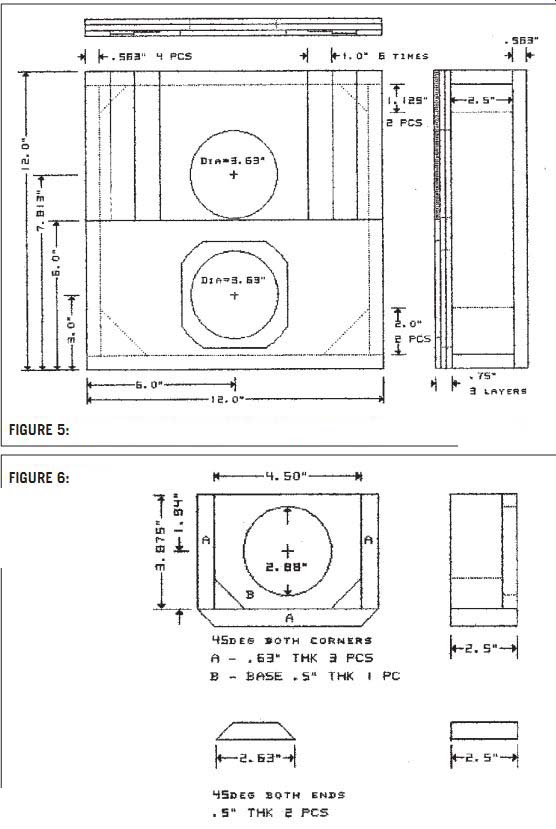
FIGURE 5: Treble speaker front panel with sides and corners.

FIGURE 6: Treble enclosure internal sub assembly and deflecting pieces.
The round hole for the Audax was slightly undersized, so I used a power driven drum sander to enlarge it. The irregular pattern for the frame was from the Audax driver itself. With the Audax face down and centered, I traced its out line on to the first panel. I rough-cut the hole for the frame with a saber saw and filed the edges to fit. After finishing the holes, I cut panel one to its final size 12×6×.20, being careful not to break it.
I then glued panels two and three together with carpenter's glue, spreading it thinly onto the mating surfaces. For pressure I used six ordinary bricks, leaving the aligned assembly on a flat surface while the glue dried. After this I glued the shortened panel one to panel two, then checked the alignment to en sure that the Audax driver would seat properly when the glue was dry.
The three steps on each side of the tweeter are added to reduce diffraction effects. They were fabricated from very thin material approximately .066 ” thick and glued in place after the front panel was completed. Note that one way to get the desired result uses strips having staggered widths of 1, 2, and 3".
ASSEMBLY
Figure 5 shows the complete treble box with its essential dimensions. Table 4 shows the parts list for the treble enclosure. I first glued the bottom side piece onto the front panel assembly. After brushing a thin coat of glue on both surfaces, I placed the bottom side piece on the front panel assembly and placed the top side piece in position without glue, putting bricks atop a board across the two sides to apply pressure.
Using the same procedure, I assembled the two side pieces, followed by the top piece. In both cases I used weights with clamps to apply pressure in the other direction. Next I glued in place four of the six corner pieces. I held the triangular pieces in place with small vises while the glue dried. Note that the two larger corners are located near the midrange driver position.
Figure 6 shows details of the center piece subassembly that forms a short TL and isolates the two drivers. You attach the finished subassembly to the rear of the front panel. I suggest cutting the matching hole in the base before cutting the base to size. First I glued the two end pieces to the base as shown in the figure using a brick to apply pressure. Next I glued the long piece to the end pieces and to the base at the same time using a brick and clamps for pressure.
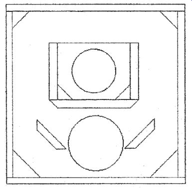
FIGURE 7: Treble speaker enclosure--simplified view showing internal
parts placement.
You may choose to glue the 45° corner pieces in place now to complete the subassembly. I suggest that you mount the Audax driver next to eliminate the possibility of interfering with this sub assembly. I used sheet-metal screws to attach the Audax, but you may prefer to use a more secure fastener. Screws hold better in the fiberboard than in the MDF.
I then fastened the subassembly to the rear of the front panel, using bricks for pressure. The two 2.88 ” holes should be in close alignment and the sub assembly sides should be parallel to the surrounding surfaces (Fig. 7). You may need to enlarge the hole to clear the Vifa magnet with the drum rasp as be fore. Also, you will need to cut relief notches for the driver solder lugs with a circular file as I did.
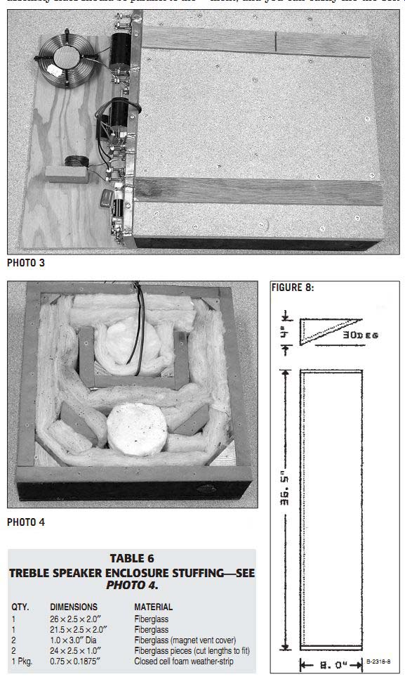
PHOTO 3: Rear view of enclosure with stuffing in place.

PHOTO 4: Rear view of completed enclosure with CO attached.
TABLE 6 TREBLE SPEAKER ENCLOSURE STUFFING--SEE
PHOTO 4.
QTY. DIMENSIONS MATERIAL
1 26 × 2.5 × 2.0”
Fiberglass 1 21.5 × 2.5 × 2.0”
Fiberglass 2 1.0 × 3.0’ Dia
Fiberglass (magnet vent cover) 2 24 × 2.5 × 1.0 ”
Fiberglass pieces (cut lengths to fit) 1
Pkg. 0.75 × 0.1875”
Closed cell foam weather-strip

FIGURE 8: Diffraction reduction wing.
The Vifa face plate is too large to fit in the provided space, but not to worry:
the acoustical need for the large face plate is nonexistent in this environment, and you can easily file the soft plastic face plate to size. Drill new mounting holes, and you are in business. A word of caution, though: if you solder the leads to the Vifa terminals, be careful not to overheat the lugs or you will think you have ruined the driver; that is, until you resolder the flexible lead to the voice coil.
I placed a large thin washer on the edge of the tweeter face plate to reduce diffraction effects. The OD is 3.63”, the ID is 2.5”, and the thickness is .10”. I drilled matching holes in the washer and used the driver mounting screws to hold it in place.
Figure 6 provides the dimensions for the deflecting plates. The 45° deflecting pieces are the last parts to attach to the rear of the front panel. You should orient them as shown in Fig. 7. With the Audax fastened in place, locate the deflectors as close as possible to the Audax driver and more or less equidistant from the other surfaces as shown, then glue under pressure.
I used 5/8” closed cell PVC foam weather-strip to seal the back of the enclosure.
After applying the weather-strip, I centered the back and drilled mounting holes for it. I used a #6× 1.5” bit to drill and countersink in one operation. Table 6 lists the stuffing for the enclosure.
I used 23 screws on 3 ” centers where possible to attach the back. The power leads emerged at an angle from the top edge. I did not consider minor leakage at this location a problem. Photo 3 shows the open-back of the enclosure after drilling the fastener holes, mounting the drivers, and installing the stuffing . Photo 4 shows the completed en closure with the crossover attached.
DIFFRACTION WINGS
My original speaker had a diffraction wing on each side to reduce the diffraction effect at the enclosure edges. For practical reasons, these wings were stepped, although I realized that slop-ing wings were preferred. I have changed to wings with a 30° slope. Fig ure 8 shows the dimensions and Table 7 shows the parts. I filled the space be hind the wings with fiberglass to pre vent suck-out by Helmholtz resonance.
The wings are attached with pins set in the upper end of the bass speaker.
The pins extend into the corner pieces at the top of the bass box and extend into matching holes in the wings.
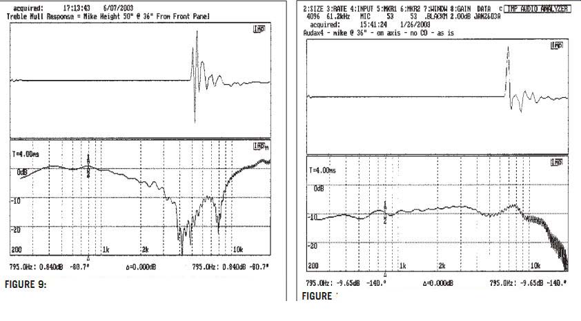
FIGURE 9: Treble speaker null with tweeter and midrange opposing--CO
bypassed. B-2318-9
FIGURE 10: Response of AUDAX4 mounted in enclosure with tweeter and CO disconnected.
TREBLE SPEAKER CO PHASE
First I checked the treble CO for quadrature output at 4kHz with an oscilloscope Lissajous pattern taken at the speaker terminals. I disconnected a lead to C4 and applied the power to the junction of L2 and C5. I used a scope gain adjustment to compensate for the different driver loads. The Lissajous pattern formed by the voltages at the speaker terminals was very close to a perfect circle indicating a 90° phase difference as required by the first-order CO design.
TEST ARRANGEMENT
Photo 5 shows the test arrangement I used to evaluate the new treble speak er. I placed it next to a dummy bass speaker enclosure, which I placed on the floor against the garage door. I placed the diffraction reduction wings on the floor as shown in the photo. De tails of the wing construction are provided in Fig. 8 and Table 7.
I used the Liberty Instruments IMP to make the frequency response and impedance measurements, with the mike hanging from the ceiling 36 ” above the front panel. I used a 4ms win dow with .BLACKM weighting for the response measurements. Other settings are shown on the plots. I powered the treble speaker with a 20W home-brew solid-state DC-coupled amplifier, which passes an almost perfect 10kHz square wave as you can see on a 20mHz dual trace scope.
Note that the speaker system is on its side with the dummy bass box resting against the garage door. Therefore, what I call height is actually the horizontal distance from the garage door to the mike, and what I call distance is actually the vertical distance from the front panel to the mike.
TREBLE SPEAKER ACOUSTIC PHASE
This test will determine the optimum listening height vs. distance to the listener.
Since both treble unit drivers are positioned above the seated listener, it is important that the optimum angle be below the horizontal by a small amount.
The acoustic phase test is the simplest of two methods that I used to determine the optimum listening height.
It used the Liberty Instruments IMP to locate the phase null resulting when the midrange and tweeter were cross connected without benefit of the CO. Of course, it was necessary to use an Lpad to balance the gains. The best null was obtained moving the mike "vertically" at 36” "distance" in front of the panel while also adjusting the Lpad to balance the amplitude. This "vertical" movement was easily accomplished with the mike suspended by its cable from a long piece of wood that slides on the overhead garage door tracks.
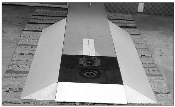
PHOTO 5: View of test arrangement on garage floor with mike hanging
from adjustable support near ceiling.
=========
TABLE 7 MECHANICAL PARTS LIST FOR WINGS
QTY. DIMENSIONS MATERIAL
4 36 × 3.5 × 0.5 ” MDF (side piece) 4 36 × 8.1 × 0.5 ” MDF (front piece) 8 4.0 × 8.1 × 0.25 ” Plywood (triangular end pieces) 2 36 × 2 × 2 ” Fiberglass (fill)
=======
The final result in Fig. 9 shows good cancellation at 4kHz, the CO frequency, but the phase difference does not stay small over a wide band. Using the mike location (50 ” height at 36 ” distance), I calculated the residual offset for this design. Then using this residual offset, I calculated the optimum height for the various distances as shown in Table 2.
The optimum height of 45” is about right for my seated position at 11' distance. Echoes were a problem when used an alternate measurement method.
MIDRANGE RIPPLE REDUCTION
The original Audax4 response is shown in Fig. 10. I have spent much time trying to find the reason for the uneven response, running many tests, making changes in the stuffing inside the enclosure and tests outside the enclosure, and concluding that the cause lies in the driver itself.
Testing with a small electret mike, using 5kHz excitation of the driver, I discovered the following with the mike almost touching the speaker moving system.
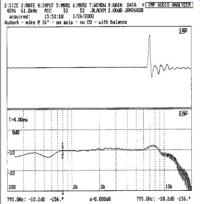
FIGURE 11: Response of AUDAX4 mounted in enclosure with tweeter and
CO disconnected but with added weight. B-2318-11
The signal was strongest at the junction of the cone and dust cover but de pended where on that junction I placed the mike. It was weakest near the point where the power leads attached to the voice coil former and strongest opposite this position. The voice coil appeared to be rocking at this frequency. I concluded that the cone possibly was unbalanced by the power leads.
To test this theory I added a 0.3 gram of mastic rolled into a short cylinder at the point of maximum output. Figure 11 shows the resulting response. I used this modification when making all the tests reported here. I also added this material to the two speakers systems that I regularly use and so far all the weights have stayed in place.
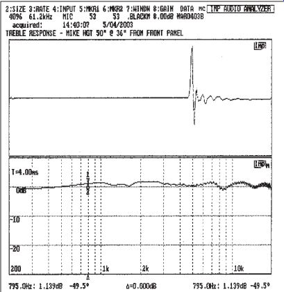
FIGURE 12: Response of treble speaker with VIFA tweeter.
TREBLE SPEAKER FREQUENCY RESPONSE
I obtained the quasi-anechoic frequency response using the test setup de scribed in a previous section with the Liberty Instruments IMP equipment.
The microphone was positioned at 36" "distance" and at 50” "height," which I determined was the point that gave equal acoustic path lengths from the tweeter and middies to the mike. This point is also on the optimum path to the seated listener in my listening area.
Figure 12 shows the first arrival response on the path of optimum height.
A listener on this path receives the first arrival that is unaffected by the vertical asymmetry peculiar to the first-order CO. I have not included the degradation caused by horizontal effects, be cause this is not as severe when the drivers are in line vertically.
COMPENSATING THE BASS SPEAKER
Response measurements on the bass speaker reported in Dec. '02 aX indicated the response at 30Hz to be -6dB below the maximum for the bass driver.
I tried to compensate for this rolloff.
Figure 13 shows a circuit that I am using that puts a 3dB boost at 30Hz and more at lower frequencies. I use one stereo circuit in series with the CD/DVD output to the receiver CD input and another stereo circuit in series with VCR/TV output to the AUX output on the receiver.
When using the compensation, I by pass the receiver tone controls. When listening to FM radio, I switch in the receiver tone control set to the +3dB point. I have not experienced any infra sonic effects when using the boost. This is a clumsy arrangement that I hope to improve upon with the next round of upgrades to the entertainment system.
CONCLUSIONS
I found the design of the treble speaker to be much more difficult than expect- ed. The coaxial approach involves timing and interaction phenomena between the midbass and tweeter that ap pear unavoidable, at least in the small sizes. On the other hand, it gives good results with little effort.
The separate driver approach opens up a can of worms that only worsens as the separation of the drivers increases.
In the simplest case of the first-order CO the vertical pattern is asymmetrical.
With normal polarity G.R. Koonce's data shows a deep dip above the optimum angle and a shallow but broad maximum below the optimum angle. I notice this dip when standing close to the speakers and the sound becomes dull.
For an in-line vertical arrangement the horizontal effects occur because of differences in the horizontal patterns rather than because of delay differences between the drivers. The horizontal degradation, therefore, is not as severe.
The bottom line as far as I am concerned is that the separate approach leads to audibly better sound quality.
This is quite noticeable at the higher power levels.
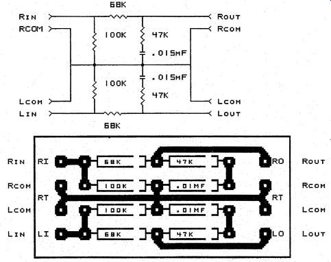
FIGURE 13: Bass equalizer schematic and layout resistors. 1/4W 5% or
better capaci tors. Film type, preferably polypropylene. B-2318-13
------------------
Also see: WHY SPEAKERS HAVE SLANTED FRONTS, PT. 4