A 6AS7/6080 CIRCLOTRON AMP---Check out this affordable, relatively easy to assemble project that's a good introduction to circlotron amp design.
-------
Searching for a better sound from your speakers?
Try this 6AS7/6080-based amp design featuring a circlotron configuration.
By Monny Nisel
I started this project a couple of years ago. I owned a pair of moderately efficient speakers and wanted to build--on a limited budget--a good sounding amplifier to drive them. So it was no surprise that I'd have to compromise somewhere. My search for a suit able schematic turned out ones with heavy and expensive output transformers or/and expensive output tubes. This was not exactly what I was looking for, so I decided to put something together my self. I ended up with a circlotron configuration using a single 6AS7/6080 with an output transformer, capable of delivering no more than 6 - 9W of output power but sounding beautiful.
I would like to stress from the beginning that this project, as conventional as it looks, is quite unorthodox with respect to some parts used and even some operating conditions of the output stage.
It may not please the high-end sophisticated user, but may appeal to the hobby ist with a desire to experiment for a better sound. A look at the amplifier schematic (Fig. 2) shows a marriage be tween a Williamson-type input/splitter stage and a circlotron-type output power amplifier with a driver stage to interface the two. A power supply section of the schematic looking more elaborate than even the regular circlotron type should prove simpler and less expensive to build than it looks.
THE CIRCLOTRON
The circlotron output stage was patented in 1954 by Alpha M. Wiggins from Electro-Voice as a high-quality audio amplifier, and the company built several models in the following years. A simplified schematic of the circlotron configuration is shown in Fig. 1. The two output tubes are connected in series with two power sup plies in a closed circle with the load connected to the cathodes of the tubes.
In a theoretically balanced state, when the two currents (I1 and I2) through each half of the circuit are equal, they cancel each other through the load, so you must assume that the current flows only along the circle, hence the circuit's name.
Any imbalance between the two currents, such as the one generated by drive signals applied to the grids, translates in a current through the load following these signals. Driving the tubes with opposite phase signals the two currents in the load to add the same way as in a conventional push-pull circuit. But unlike in the classic push-pull circuit, the load is connected in parallel to the tubes and does not carry the DC supply, which is a great advantage.
There are a few more advantages, but the greatest and the one that prompted me to try this circuit was the unpretentiousness of the output transformer.
When compared to the conventional push-pull amplifier, the impedance of the primary winding of a circlotron out put transformer is just one-fourth of the plate-to-plate winding impedance of the former. A glance at the two configurations shows that for the same operating conditions and from the AC signal point of view, in the regular push pull you can regard each output tube as being in series with the entire (double) winding, whereas in the circlotron the two output tubes are in parallel with one half of that winding.
A low impedance output transformer means fewer turns in the windings as well as less distributed capacity and leakage inductance, hence a better frequency response. Switching transients are practically nonexistent because the current in the primary winding is never switched off regardless of the class of operation; there is no need for air gap in the core because no DC flows through the winding. So you deal practically with a simple, low impedance,
ABOUT THE AUTHOR
Monny Nisel is currently working part-time as a consulting electrical engineer after retiring from the aerospace industry in Montreal, Canada. He started building tube amplifiers in the early fifties and restarted designing and building in the nineties. He holds an electrical engineering degree from The Polytechnical Institute in lassy-Romania and is a member of the Order of Engineers of Quebec Canada.
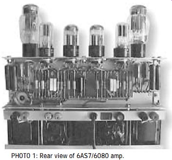
PHOTO 1: Rear view of 6AS7/6080 amp.
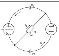
FIG. 1 : Simplified circlotron configuration.
single primary winding type trans former, operating in a push-pull mode due to an ingenious arrangement. Such a transformer costs a lot less than a regular push-pull transformer, and these savings may justify the cost of a more expensive power supply.
THE OUTPUT STAGE
One of the reasons for choosing the 6AS7 tube was my idea that I could eventually supply it with low plate volt age and high current, though it seemed to go against RCA recommendations as well as GA's published projects using this tube. I wanted to try to push the current as high as possible to see what difference it would make in the sound.
Choosing a plate voltage of 120V, I plotted a 1 k-O load line in a single mode operation and figured out a 1.8 k-O plate-to-plate load in a regular push-pull operation, or a 45 0 ohm load impedance (one-quarter of 1.8 k-O) in a circlotron arrangement. It is common knowledge that a 45 0 ohm impedance out put transformer is not an off-the-shelf item, so I had to either have one custom-made or improvise something . . .at least to experiment with temporarily. The first choice would have been quite expensive and practically defeat the purpose of the full exercise, so I went straight to the second.
I figured out that an impedance ratio of 450 to 8 ohm or 56/1 can be easily found in a power-supply-type transformer. A 120/16V transformer has a 7.5/1 turns ratio (120:16) or a 56.25/1 impedance ratio, which was exactly what I needed.
Combined with the knowledge that the transformer could be a very simple type, I decided to try it and I was not disappointed; as a matter of fact the sound was so good I never had to revert to the first choice. The amp schematic is shown in Fig. 2.
With a 30 0 ohm resistor in the cathode of each triode, the bias was close to 34V and current reached 110mA. I used the two trimpots P2 and P3 to balance the currents in the two halves of the tube. I found that most of the 6AS7s or 6080s I tried had slightly different currents when operating under the same condition, but sometimes the difference was quite noticeable.
SETUP
Because I wanted to avoid any DC cur rent through the output transformer, I needed to balance the currents through both tubes. I made no attempt to adjust the current before the tube had reached thermal stability-approximately five to ten minutes after the amplifier had been switched on.
For those who noticed the somewhat unusual way of connecting the lower side of the adjusting potentiometers P2, P3 to the negative rail of the opposite tube, I found that in this way adjustment is a lot easier and more stable. As a matter of fact, the negative rail of the opposite tube is practically the negative rail of the same power supply whose positive one is connected to the tube for which you make the adjustment. With this setup the output power before clip ping was close to 6W, provided the DC voltage supply of each tube could be maintained at 148-150V (Table 1). My main supply voltage sometimes drops to 107-V and the DC supply and output power follow suit; although it does not make a difference in volume or sound quality, it shows when I mea sure the power. At this low DC voltage supply even a few volts less in the main makes a difference in the output power.
Because the two power supplies are floating with respect to ground, I connected the two 16 k-O resistors across the output transformer primary with the median point connected to ground, thereby producing an artificial reference to ground of the output stage.
The 16 k-O value, which may seem a little high for this purpose, is a com promise that should not short any significant amount of output power. This problem was solved in Wiggins' original design by using an output trans-
PHOTO 2: Front view.
former with a middle tap connected to ground; the same can be accomplished here by using a 2 × 120/2 × 16V transformer, such as part #037013 201 from Plitron with the two windings on each side in series and the primary tap grounded. I noticed that some of the 6AS7s I used--especially the GA version--have a tendency to thermal run away. I had better results with the 6080, especially the WA or WB versions or even with the 6AS7G, all having a bigger heat radiator strapped to the grid pylons; you should consider using this type of tube, especially when deciding to push the dissipated power a bit higher.
THE POWER SUPPLY
The power supply must deliver three different DC voltages and the 6.3V heaters supply. This task, as complicated as it looks at first glance, is accomplished with only two inexpensive off the-shelf transformers. You can obtain the dual voltage for the output tube from a Hammond type 182 H 117 transformer, which has two separate secondary windings capable of delivering 117V at 342mA each. A bridge rectifier and a 2000µF capacitor complete the power supply for the output tube, delivering approximately 150V DC. I found that for the output stage a single big capacitor is quite adequate instead of a full-blown pi filter using smaller capacitors. The perfect symmetry of the output stage leads to ripple cancellation in the load, to a degree that is barely audible even close to the speakers. The high voltage for the input/splitter and driver stages as well as the 6.3 AC for the heaters is supplied by a part #P-T6415 power trans former from Antique Electronic Supply.
I was concerned that the 6AS7 might fail during testing and short the power supply, so I inserted a 1A fuse in series with the positive rail. I never had a tube failure, but the fuse proved useful when I needed to disconnect one side or the other for testing and measurements.
All the electrolytic capacitors are computer grade, and I purchased them from surplus stores at a very low price. I found Mouser Electronics stores had a good selection of them. The same goes for the transformers; you could use any type with similar parameters.
In one version of the amplifier, I used a couple of 20VA 120/120V transformers, which I removed from bath room-type isolation outlets, for the out put tube power supply. The power sup ply is the most expensive part of the amplifier and reducing its cost greatly impacts the cost of the entire amplifier.
In a stereo version of the amplifier you can replace T1 with part #P-T272JX power transformer (also from AES).
SPLITTER AND DRIVER STAGES
After experimenting with a couple of different designs, I settled for the Williamson type input/splitter stage.
Though the cathodine splitter stage has less gain than other configurations, the input stage compensates for it, and apart from sounding better than other designs I tried, the entire stage uses one or two capacitors less than the other classical designs, a feature I liked. The following stage, the driver, had to provide over 200V pp to drive the output tubes biased at 34 to 59V DC, and for this purpose I had to supply the tube with higher volt age than the output stage, further complicating the power supply.
I used the same tube, the 6SN7, for both input/splitter and driver stages in an arrangement which is commonly used by manufacturers and experimenters alike. The 6SN7 is a very linear and good-sounding tube; it is also not expensive and can be easily found at any tube dealer and certainly in the possession of any respectable tube hobbyist. I used a RCA 6SN7 GTB tube for the driver stage and a Rogers tube as the input/splitter. I found that this combination has a good tonal quality, though I could not find significant differences using other brands of tubes.
I tried to keep the stage simple by not using trimpots to balance the out put of the two sides. Instead, I chose to measure the driver's plate resistors to get their value as close as possible and have the tube with the two halves match. Apart from degenerative local feedback in the two stages, there is no global feedback; any small amount I tried was, in my opinion, muffling the sound, so I decided not to use it. The input voltage needed to drive the amplifier to full power was 350mV.
ASSEMBLY AND ADJUSTMENT
I assembled the amplifier in a stereo version in a somewhat unusual com-
pact vertical chassis to fit a certain space in my system. Though this design has some advantages, I do not recommend it because of the difficulties of the mechanical work involved. Instead, you can easily install the components on a regular chassis, in a classic arrangement with all the transformers, tubes, and bigger electrolytic capacitors installed on top of the chassis and the smaller components underneath either in separate mono or stereo versions to fit your taste.
Once assembled and with components connected, the amplifier should work at once. However, you should check the correct connection of the components before power-up, especially at the output tubes where a mistake in biasing can overheat and eventually destroy the tubes if left unattended for a long time. You should take special care when wiring the trimpots P2 and P3 and the grid discharge resistors.
The next step is to adjust the output tube bias using P2 and P3 potentiometers. With a voltmeter connected in parallel to the cathode resistor R18, I adjusted P2 until I read 34V on R18, and repeated the same operation on the other half of the tube. With this bias voltage the current should not be more than 110 to 115mA. I made the adjustment only five to ten minutes after switching on the amplifier to let the tube reach thermal stability.
As mentioned previously, one of the reasons for using the 6AS7 was to find out how a tube already supplied with low voltage and high current will be have when current is pushed to the maximum--or even higher--recommended by the manufacturer. By turning P2 and P3 cursor to the cathode side, I could increase the current to over 140mA, which is above the 125mA maximum recommended. I always did it in small increments, leaving the tube to stabilize after each adjustment and watching for red spots on the plates.
At 140mA the voltage drop on the cathode resistor reached 42V, leaving the plate supply no more than 110V and sometimes less depending on the main supply. As the plate voltage dropped, so did the output power--as expected--and clipping settled in earlier. I could not measure distortions but they must have increased as well.
THE SOUND
Though the sound was quite nice from the beginning, once I started increasing the current the sound seemed to gain more body and become richer, especially in the lower side of the frequency spectrum, which made it really pleas ant to listen to. At this point the bias was approximately 23V and the dissipated power reached 15W, way up from the 13W maximum recommended.
Amazingly enough, I've never experienced any tube failure and I noticed no red spots on the plates.
As a matter of fact, a couple of 6AS7Gs I've been running for almost two years at close to 14W dissipation power in the amplifier I built seem to be working fine. Although in my experiments I went even further reaching 150mA plate current, I found there is no advantage in going that far. Apart from thermally overstressing the tube to the point of damaging it, power de creases dramatically and the distortion becomes audible even at lower volume.
So what is a good point to run the tube to take advantage of the higher current without going overboard ? Table 1 shows the parameters when I run the tube in four different conditions, with different plate voltages. I preferred to run the tube in condition no. 1 and in crease the current to 125mA by adjusting R2 and R3 until the voltage drop on the cathode resistors reached 37V; the dissipated power is just above 13W. For those with 120V main, condition no. 2 gives close results.
For slightly increased power but also a little change in sound conditions, nos. 3 and 4 apply. Those two conditions in Table 1 show that you can achieve higher output power by using higher supply voltage. I chose the 150 and 175V AC supply, respectively, because I found transformers with double secondary 0.2 × 150V and 2 × 175V at very reason able prices. The 2 × 175V transformer is part #037053201 by Plitron and the 2 × 150V is part #RC 0100 040 1 from SUM R. In case you use the 175V supply, the electrolytic capacitors C7 and C8 should be at 250V minimum.
With regard to the output trans former, I experimented with two different types. I started with a regular E&I type 120/17V and switched over to a toroidal type 120/16V, both ranging from 80-100VA. Though there was not much of a difference in power output, each transformer had a different sonic signature, and though I preferred the sound of the latter, I used the former to build the amplifier due to assembly constraints.
TESTS AND MEASUREMENTS
I have not done any specific performance tests apart from output power and a frequency sweep at nominal ...
-----------------------------TABLE 1 CONDITION
Uac NL volt 115 124 150 175 Uac FL volt 113 121 144 169 Udc volt 148 156 166 216 Ua volt 112 120 126 156 Rk ohm 300 330 375 700 Ug1 volt -33 -36 -40 -59 Ia mA 110 120 110 85 Pd watt 12.3 14.4 13.8 13.2 Pu watt 5.6 6.5 8 9
Abbreviations
Uac NL, FL: TR 2 secondary voltage with no load or full load Udc: total rectified DC voltage Ua: DC voltage between plate and cathode of the output tube Rk: cathode resistor Ia: plate current Pd: dissipated power Pu: output power
------------------------
PARTS LIST COMPONENTS DESCRIPTION REMARKS RESISTORS
RESISTORS R1 680R 1W carbon composition (cc) R2, R10, R11 47k 2W metal oxide (mo) R3 470R .5W cc R4, R5 33k 2W mo R6 27k 2W cc R7, R8 470k ½W cc R9 820R 2W cc R12, R13 1k 1W cc R14, R15 27k 1W cc R16, R17 220k ½W cc R18, R19 300R 10W wirewound R20, R21 100k 1W cc R22, R23 16k ½W cc R24, R25 200k 1W cc R26, R27 10R 2W cc R28 1k 2W cc CAPACITORS C1, C2 250nF 400V polyester C3, C4 680nF 400V polyester C5, C6 100µF 100V electrolytic C7, C8 2000µF 200V (250V) electrolytic C9, C10 100µF 500V electrolytic C11, C12 47nF 600V polypropylene C14 22µF 450V electrolytic RECTIFIERS D1-D4 1N4007 diode 1A 400 PIV BR1, BR2 P-QBR-84 (AES) bridge rectifier 8A 400V TRANSFORMERS TR1 167P16 9(Hammond) 117/16V-80VA or
037013201 (Plitron) 115×2/15×2-80VA TR2 182H117 ( Hammond) 2×117V 342mA TR3 P-T 64159 (AES) 700VCT 70mA 6.3V 3.5A TUBES T1, T2 6SN7 GTA (GTB) T3 6AS7G,(GA), 6080
----------------------------
---------------
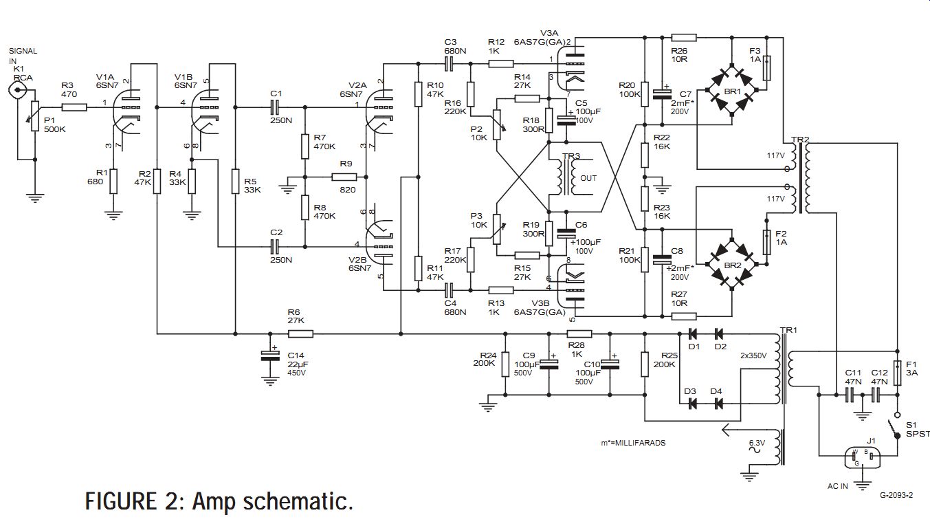
FIGURE 2: Amp schematic.
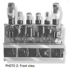
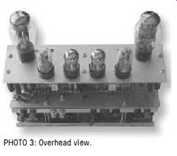
PHOTO 3: Overhead view.
... power, due to a lack of dedicated equipment. However, I did extensive listening tests myself, and with other people, including a couple of audiophiles, and everybody liked what they heard very much; single instruments such as the piano or the guitar as well as female voices were really amazing.
Sometimes it was difficult to realize that the sound came from an amplifier using this type of an "output" trans former. Any listening test should be done only after the amplifier has enough time to warm up (15 to 20 minutes).
I used three different types of speakers for listening tests: a pair of Fisher XP-1as, a pair of Acoustic Research AR 4xs, and a pair of JBL CF 120s. The best match was the JBL pair, which happens to be the most efficient, though with the AR 4xs, which are known for their low efficiency, the sound was strong enough to use no more than one-third of the volume in normal living room listening conditions. The frequency response of the amplifier seems to be very good from the listening test point of view, though the sweep showed a difference of ±3dB between 40 and 20,000Hz. The frequency response will be different for different transformers, and it seemed quite funny to measure the frequency response of power transformers meant to work only at 60Hz; amazingly enough some of the trans formers measured have quite a wide frequency range.
I am not advocating the use of power transformers instead of normal output transformers, though I tried them on many other occasions with good listening results. I am convinced that a properly designed output transformer--or even an autotransformer, for that matter-would yield better performance. As I mentioned before, I tried to keep the cost as low as possible, making convenient compromises. Regarding the transformers for the output stage or power supply, you can use any type or manufacturer you find convenient, pro vided they have the same parameters as the ones specified.
CONCLUSIONS
This project includes a few features that make it different from other designs. First of all, it is a beginner's circlotron.
Though more complicated than a regular amplifier, it is still affordable and can be assembled without great difficulty by anyone with little experience with tube amplifiers. Also:
• It uses a single 6AS7 in a circlotron configuration with an output transformer.
• It uses lower than recommended volt age and maximum current.
• The output transformer is a power transformer conveniently chosen to match the output impedance of the stage.
• The cost is kept as low as possible by using inexpensive--and where possible--surplus parts.
AND A FEW MORE WORDS
The experiment bug drove me to break another taboo. I tried the amplifier with fixed bias without any cathode resistors and with 145V DC at the plates, and it seemed to work quite well. The output was 9W, but, again, it produced a different sound that I liked less than the one from the automatic bias version.
SOURCES
Antique Electronic Supply 6221 S Maple Ave Tempe AZ 85283. 480-820-5411. FAX 480-820-4643
info@tubesandmore.com www.tubesandmore.com
Hammond 256 Sonwil Dr. Cheektowaga, NY 14225
716-651-0086 FAX 716-651-0726 www.hammondmfg.com
Mouser Electronics. 1000 North Main St. Mansfield, TX 76063 800-346-6873 FAX 817-804-3899 sales@mouser.com www.mouser.com
Plitron 8-601 Magnetic Drive Toronto, ON M3J 3J2 Canada 416-667-9914 FAX 416-667-8928 1-800-PLITRON (1-800-754-8766) www.plitron.com
SUM R, Richard Sumner Technology Inc. 29 Connell Court, Unit #17 Etobicoke, Ont., Canada M8Z 5T7. (416) 251 2523. FAX (416) 251 0401. www.sumr.com
-------
Also see:
MAKE A PANEL-CUTTING JIG---Can your table saw cut it? Discover how this jig can make your next speaker-building project a breeze.