CAPACITOR ESR TESTER--THE GOOD, THE BAD, AND THE LEAKY---Build this handy test unit to measure and track down faulty capacitors.
----
The good, the bad, and the leaky ....
How about an in-circuit capacitor tester to take the strain out of tracking down faulty capacitors? No need to unsolder any capacitor, simply check it in-circuit, from thousands of microfarads down to a hundred nano farads. In most cases, parallel coils or low value resistors are no problem. Even shorted caps may be revealed in-circuit and polarity is irrelevant for the tester. High ESR? Replace!
Design by Flemming Jensen
The most significant property of a capacitor is its capacitance, but besides that there's another important factor, namely the so called ESR, or Equivalent Series Resistance. An ideal capacitor is a purely re active component with a 90° phase angle between current and voltage. In the real world, however, a capacitor needs to be modeled as an ideal capacitor in series with a resistor representing the losses introduced by the component. The equivalent circuit is shown in Fig. 1. Sure, you can measure capacitance with a capacitance meter, which is pretty common nowadays, but unfortunately this test won't tell you any thing about the capacitor's quality-- you need to know the ESR as well.
Over time, electrolytics tend to dry out, which will raise their ESR and inevitably the voltage drop inside the capacitor. Evidently, the pure reactance Xc cannot produce heat, due to the 90° phase shift between voltage and cur rent, but the ESR can, and in switching circuits the resultant heat will cause a further degradation of the capacitor's quality, i.e., a further rise in ESR. It's fairly common to find electrolytics that on the face of it have lost only just a few percent of their rated capacity although their ESR is in the hundred ohms range. Obviously, such a component acts as a load just running hot and wasting a lot of energy.
THE MEASURING
The capacitor under test, C.U.T., is fed with a 100kHz constant-current square wave signal. The ESR value is deter mined by measuring the AC voltage drop across the C.U.T. If the capacitance is high enough compared to the frequency, the voltage drop over the internal reactance is negligible and the drop is caused only by the ESR. This voltage is converted to DC and fed to the voltmeter section.
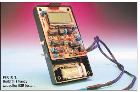
PHOTO 1: Build this handy capacitor ESR tester.
AC to DC conversion of a 100kHz signal in the millivolts range presents a real design challenge. Furthermore, the conversion needs to be as linear as possible because you want to use an ordinary 200mV DVM readout. It goes with out saying that an ordinary diode rectifier will not suffice, and an active diode rectifier with opamps will have a hard time working at 100kHz and a few millivolts.
The solution we came up with is a synchronous rectifier--essentially a polarity changer controlled by the same generator that supplies the 100kHz test signal. This circuit works surprisingly well and is cheap, too! A simplified version of the circuit is shown in Fig. 2. Here, the C.U.T. is assumed to be a 100µF with an ESR of 10 ohm. As shown, the reactance is negligible and the ESR, which is purely resistive, is dominating. Although this principle works well, further reduction of the reactive influence is called for.
Figure 3 shows an example in which the C.U.T. is 0.1µF cap whose ESR is 0 ohm. As mentioned, we use a relatively high frequency to make the reactance negligible while enabling even the smallest electrolytics such as 0.1µF to be tested. For this it is necessary to reduce the influence of the beginning integration of the waveform even further.
The ESR is zero and the reactance is 15 ohm. As you can see, the integrated waveforms presented to the differential amplifier inputs result in a sawtooth centered around 0V at the output.
After integration, in the RC network that follows, a DC level of 0V is fed to the voltmeter circuit. If the C.U.T. also represents an ESR of, say, 1 0 ohm, the saw tooth at the output will still have the same waveform. However, it will be DC shifted in the positive direction by an amount representing the ESR value.
After integrating the sawtooth away, the output will give the proper reading of 10 ohm, excluding the 15 ohm reactance.
LOW-ESR CAP OR SHORTED CAP?
You may question whether you're testing a low-ESR cap or simply a shorted one. A simple DC ohms test is usually enough to decide this. No need to get out the multimeter--with a push of a button the ESR tester becomes a DC ohmmeter and your display should change to a higher ohm reading. If it doesn't, the odds are you have a short ed cap on your hands.
SOME PRACTICAL ESR VALUES, PLEASE?
So how high will the ESR be then? Well, that depends on where the capacitor is used, the type, the make, the volt age rating, and so forth. A 2,200µF reservoir capacitor with an ESR of 10 ohm may be fine in a linear power supply, while a 2,200µF one having 1 ohm ESR may be grossly inadequate in a switch mode PSU.
In general, if a large capacitor, as in this example, reads more than 1 ohm, you should be suspicious and run a com parison on a similar component. But don't worry! It won't take long before you are able to distinguish bad caps from good ones. If you regularly are re pairing SMPSUs, TV sets, monitors, and so on, you will soon appreciate the ESR tester.
CIRCUIT DIAGRAM
Let's look at the circuit diagram of the Capacitor ESR Tester (Fig. 4). A 200kHz square-wave generator is built around IC1. This signal is divided in IC2.A, which in fact constitutes our bipolar 100kHz test signal generator. Series resistors R6 and R3-P3 on the Q and outputs of IC2.A give the generator a ...
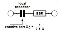
FIGURE 1: The most important property of a capacitor is its capacitance, but beside that there's another important factor, namely the so-called ESR, or Equivalent Series Resistance.
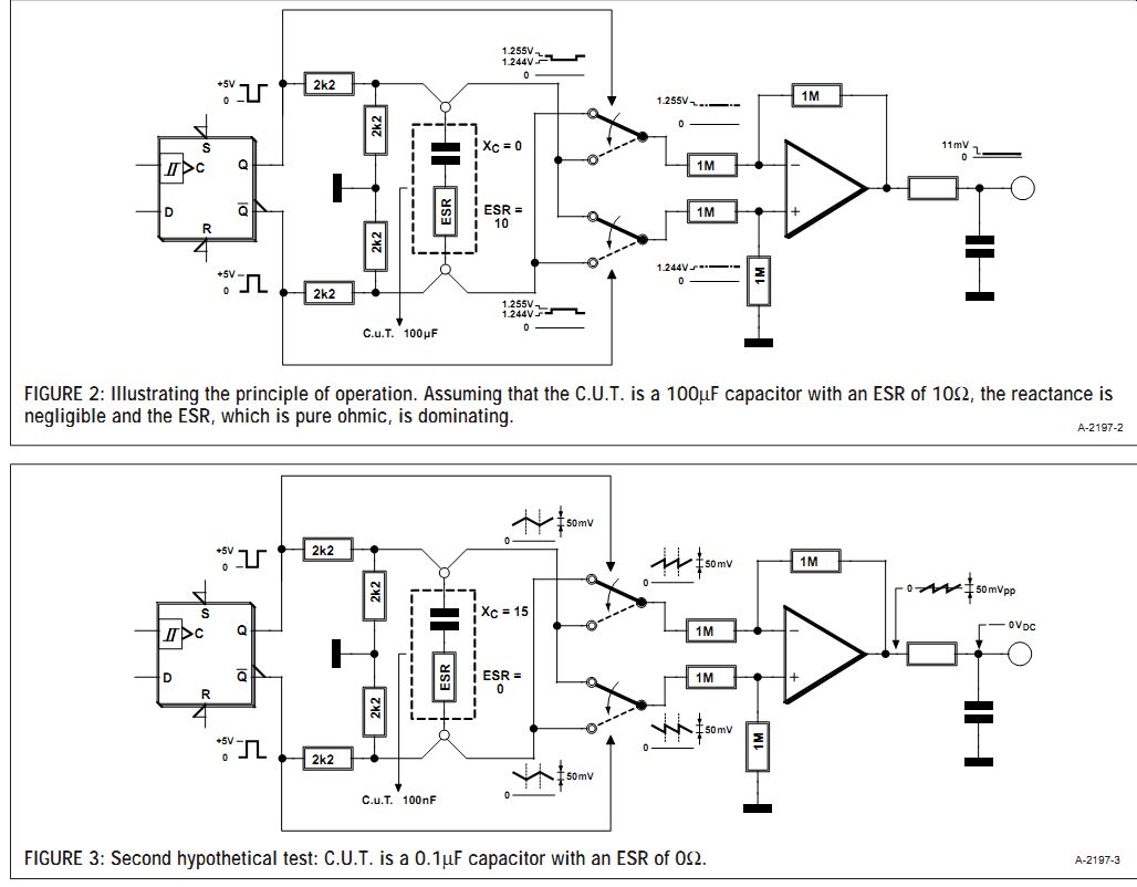
FIGURE 2: Illustrating the principle of operation. Assuming that the
C.U.T. is a 100µF capacitor with an ESR of 1 0 ohm, the reactance is
negligible and the ESR, which is pure ohmic, is dominating.
FIGURE 3: Second hypothetical test: C.U.T. is a 0.1µF capacitor with an ESR of 0 ohm.
... high output resistance compared to the low ESR, and, essentially, make the generator act as a 100kHz, balanced, constant-current generator.
The voltage drop across the C.U.T. is taken to IC3, four bilateral switches coupled as a controlled polarity changer, changing polarity in sympathy with the outputs of IC2.A. This enables IC3 to act as a (rudimentary) ADC. IC4.A, a differential amplifier, converts the differential signal into a single-ended signal, i.e., one which is referenced to ground.
IC4.B amplifies the signal such that it can be applied to a 200mV voltmeter.
IC9 is the voltmeter IC. Here the ICL7106 is used with an LCD, all in a standard configuration. The LM358 in position IC8 is a comparator that tells you when it's time to change the battery. IC7, finally, generates the negative supply rail for the circuit.
As shown in the circuit diagram, the test probes carry two screened wires each. Each probe carries a signal wire (e.g., "A") and a measuring wire (e.g., "B"). More about the probes in the next section.
CONSTRUCTION
Elektor Labs designed a compact print ed circuit board for the Capacitor ESR Tester. The resulting double-sided through-plated board design is shown in Fig. 5. As appropriate for a test instrument, the board is designed such that all adjustment points are easily accessible, in this case, from the sides of the board (multiturn presets P1, P2, P4, P5) and from the top (preset P3).
Although the construction of the board follows standard practice (of which the main maxim is: work carefully), a few things should not be left un mentioned. First, the circuit board has a screening ground plane at the component side, so you should take care to avoid short-circuits by solder blobs or solder hairs between component terminals and the ground plane. Second, as certain, check, and double-check the polarity of any polarized component, in particular the tantalum capacitors in positions C3, C4, and C5. Tantalum capacitors when reverse polarized have a nasty habit of exploding and emitting hideous fumes.
Finally, we recommend using sockets for all ICs (except IC9) and the LCD. The latter is easily made by cutting a 40-pin IC socket in two (lengthwise) and using the two 20-way socket strips. You should drill small holes in the two long sides of the ABS case to allow P1, P2, P4, and P5 to be adjusted from the outside.
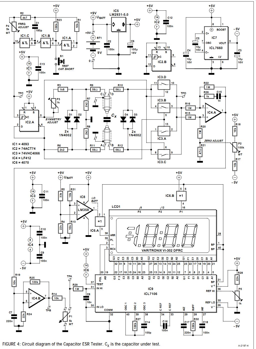
FIGURE 4: Circuit diagram of the Capacitor ESR Tester. Cx is the capacitor
under test.
Regarding the probes, their basic construction is illustrated in Fig. 6.
These two wires are soldered together as close to the probe tip as possible. In this way the voltage drop along the signal wire will not add to the measurement. The screening ensures that the test leads do not pick up noise, and that you maintain a stable zero adjustment.
THE ESR TESTER AS AN ADD-ON
The most costly parts in the circuit are the display and the 7106 A-D converter.
You can save money by deciding to use the ESR Tester as an add-on for an existing digital multimeter (DMM).
Switch the multi-meter's range selector to the 200.0mV/DC position and connect the inputs to GND and the wiper of P1. You should not be tempted to sup ply the ESR Tester from the multimeter's battery.
Remember, the ESR Tester has its output referenced to ground, so if you run it off the multimeter's battery the Tester will have its battery minus connected to the input common terminal, which is far from advisable. Use a separate battery for the ESR Tester to avoid any problems. Or if you really want to use just one battery, give the ESR Tester an add-on 9V battery, connecting the ESR Tester's regulated +5V to the plus terminal of the multimeter's battery connector and the ESR Tester's -5V to the multimeter's minus terminal.
A FEW WORDS OF WARNING
Though the ESR Tester has diode-protected inputs, it is still a good idea to discharge any largish capacitors you want to test. Some reservoir capacitors in power circuits contain so much energy that the protection circuit may burn out. If this should happen, the defective components are usually to be found in...
------------------
COMPONENTS LIST
Resistors:
R1, R13, R14, R17-R19, R31 = 10 k-O R2 = 4 k-O7 R3 = 1 k-O8 R4, R24, R28 = 22 k-O R5 = 33 k-O R6-R8 = 2 k-O2 R9-R12 = 56 ? R15, R16, R20, R22, R29 = 1M ? R21 = 47 ? R23, R25, R27, R30 = 100 k-O R26 = 1 k-O P1, P4 = 5 k-Omultiturn preset, vertical mounting, side adjust (Bourns 3266X, Farnell #347-747) P2 = 100 k-Omultiturn preset, vertical mounting, side adjust (Bourns 3266X, Farnell #347-784) P5 = 1 k-Omultiturn preset, vertical mounting, side adjust (Bourns 3266X, Farnell #347-723) P3 = 1 k-O preset, horizontal mounting
Capacitors:
C1 = 180pF C2, C9-C13, C16, C18 = 100nF C3-C5 = 10µF 10V radial C6 = 100µF 16V radial C7, C17 = 220nF C8 = 10nF C14 = 100pF C15 = 1nF
Semiconductors:
D1-D4 = 1N4002 IC1 = 4093 IC2 = 74ACT74 PC IC3 = 74VHC4066 IC4 = LF412-CN IC5 = LM2931-5,0 IC6 = 4070 IC7 = ICL7660 IC8 = LM358-N IC9 = ICL7106-CP
Miscellaneous:
LCD1 = 3.5 Digit LCD with LO-BATT indicator, e.g., Varitronix VI-302 DPRC (Farnell #478-660) S1 = pushbutton, 1 make contact Batter holder On/off switch Two miniature probes, e.g., Hirschmann PRUFI (Farnell #523-483)
Length of two-core screened cable
ABS enclosure with LCD window and battery compartment, e.g., Multicomp type BC4, (Farnell #645-758) 40-pin IC socket cut in half (see text)
-------------
HOW DOES ESR INFLUENCE CIRCUIT BEHAVIOR ?
In (fast) switching circuits, a low ESR may be crucial for proper circuit behavior. For example, in a TV set, high capacitor-ESR may lead to inability to quit stand-by mode, incorrect picture height or width, synchronization problems, interference or hum bars. In Switch Mode Power (SMPSUs) supplies, high ESR caps may lead to blown semiconductors, blown fuses, or no startup. In power circuits, a rising ESR will make the capacitor warm up, leading to even higher ESR and eventually circuit breakdown.
The usual method to troubleshoot these problems involves soldering out the capacitors, measuring the capacitance, and soldering the good ones back in. A tedious task, but what's even worse, ailing capacitors often don't show a low capacitance, are soldered back in again, and then the troubleshooting becomes really time consuming.
---------------
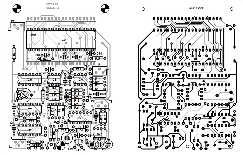
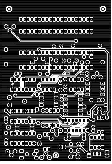
FIGURE 5: Copper track layout and component mounting plan of the PCB designed for the instrument. Double-sided, through-plated board, available ready-made.
... the protection circuit alone. The remedy should therefore be pretty straight forward and inexpensive.
ESR TESTER ADJUSTMENT
Before adjusting the instrument, be sure that you have a regulated +5V from IC5 and -5V from IC7. If you don't, you'll need to troubleshoot your circuit board.
1. Start with the voltmeter circuit. You should disconnect P1 at this point.
Connect a known, ac curate voltage source of less than 200mV to point TPA (test point A) and adjust P5 until the LCD shows the right value. Remove the voltage source. Connect TPA to TPB, short the test leads together, and adjust P2 for a "000.0" reading. Remove the connection. Reconnect P1.
2. Connect a frequency counter or an oscilloscope between TPC and GND. Adjust P4 for 200kHz counter reading or 5µs period time on the oscilloscope.
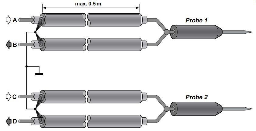
FIGURE 6: Here's how to make the four-wire test leads between the probes and the instrument proper.
Connect the test leads to a 1 0 ohm resistor. Connect an oscilloscope (in AC mode) between point TPD and GND.
Turn P3 (symmetry adjust) so that the two half cycles line up and produce a straight line. Adjust P1 for a "10.0" DVM reading.
If you do not have a counter or a scope available, turn P3 and P1 to the center of their travel. To ensure that the ESR Tester works properly, you can connect different (known, good) capacitors in series with different resistors and have these simulate capacitor ESR.
COMPONENT CONSIDERATIONS
The LF412 in position IC4 is a good choice for the differential amplifier.
Since we are dealing with high-frequency signals in the millivolts range, low drift, low offset, and high bandwidth are crucial. Many different opamps have been tested but most resulted in DC drift problems. The LF412 emerged as a good, low-cost choice causing minimal drift.
IC5, then, is a 5V regulator that works just fine at a voltage drop less than 600mV and so ensures long battery life. This regulator enables the circuit to keep working down to a battery voltage of less than 6V. IC2, a 74ACT74, is capable of delivering enough current at 100kHz to produce a nice clean square wave. IC3 is a high-speed (VHC) version of the well known 4066. Com pared to the common 4066, the effect of unwanted reactance is halved. For best performance, you should use the specified components, but all in all, quite acceptable performance is still achieved if you use an ordinary 4066 for IC3, and a 74HCT74 for IC2.
------------------
Also see: