Mail / Feedback
NEW/OLD TECHNOLOGY
It is with some interest that I read your recent article, "Vacuum Tubes Born Again in Nanotube MEMS" (Nov. '02 aX, p. 46). It seems that it's an example of the old saw, "If it's in print, it must be true." I'd just like to point out a couple of instances of misleading or missing information, or the dreaded "proof by assertion." Let's just look at the first sentence,
"Ever since the transistor was invented, engineers have lamented the slow, steady demise of the vacuum tube." Really ? This is a universal feeling among engineers?
One can, with a statement like this, imagine the engineers at Intel sitting around their CAD stations, depressed because they really want to retool the upcoming Pentium-6 as an all-triode chip. And those poor engineers at Crystal, such a blue funk must rule their professional lives be cause they are unable to make their D/A and A/D converters using transistors. Why, they probably hold a weekly service, "In Lamentation of the Depart ed Hollow State." How much better a 256 times over-sampled A/D converter would be with tubes. Ah, the good old days.
Well, enough of that. Let's look at a statement a few paragraphs later: " ... vacuum tubes simplify circuit design because they are true amplifiers all by themselves." Part of this statement is true: yes, they are amplifying elements all by themselves. But the inference that the author apparently wants us to make--that transistors are not amplifying devices--is patently wrong. The author simply should know better and--writing for an industry electronic publication--should well know the difference between voltage-controlled current sources, current-controlled current sources, and the like, and should not assume one means "amplifier" and an other does not. If, on the other hand, this is the view held by Mr. Zhu, the spokesman for the company, the author still should accept and exercise the responsibility for accurate reporting of technical points in a technical journal.
Another technical assertion made by Mr. Zhu is, well, curious: "Even today, our transistor circuits are only about 5 percent efficient." ". . . engineers could downsize their solid-state equipment into smaller vacuum-tube-inspired designs that are 20 percent efficient." This is patently and absurdly incorrect. I would challenge Mr. Zhu to directly pro duce evidence to support this assertion.
Assuming that Mr. Zhu is using any conventionally accepted definition of the word "efficiency"--that is, the ratio of power out to power in--he has at once completely contradicted the existence of millions upon millions of both transistor and tube amplifiers biased into class AB operation that are running at 40% efficiency. And his statement further ignores the fact that vacuum tube circuitry is not well suited for low impedance applications, and thus incurs the additional efficiency losses of prerequisite impedance matching devices such as transformers, not to mention the further filament power requirements. (Ignoring those last elements, there's not the slightest bit of data--be it theoretical or empirical--to suggest that there are any substantive differences in the efficiencies of two otherwise similarly biased amplifiers, one using solid state, one using vacuum tube technology.) Now, there are certainly reasons for using vacuum-tube implementations that are driven by technological requirements. For example, many of the high-power RF components used in space vehicles are vacuum-tube-based, simply because they are far more resistant to the rigors imposed by the high radiation environment of space.
But "efficiency ?" Unless Mr. Zhu has co-opted the definition of efficiency to mean something heretofore unheard of, his assertion quoted in the article is wrong.
As I mentioned at the outset, these assertions will, quite unfortunately, end up taking on a life of their own, whether they are technically valid or not. In an industry that already has more than its fair share of hokum, leg end, and mythology, more of the same is needed like yet another hole in audio's too-porous head.
D. Pierce, Boston, Mass.
HIGH GM POWER TUBES
Since I have an adequate supply of high gm tubes obtained at 50 cents per from AES tube sale flyers, I can let the ignorant in on my little secret.
6KV8s and their ilk are generally high mu triode-pentode combos; with the pentode being the interesting portion.
Also, of course, they are high-quality American tubes manufactured by RCA, Sylvania, or GE. These frame-grid beau ties were designed as IF strip amps for TVs, so they are very linear and provide 20k µmho gm at 40mA. Power dissipation on the pentode section is around 3-4W. (Yes, I prefer to use the original American nomenclature as seen in the tube manuals, thank you very much!) These tubes are very linear, and they make great cathode-follower drivers for MOSFET outputs (output impedance of 5 0-ohm can drive 4-5000pF quite nicely!) They also work very well as power grid tube drivers in Class A2 and AB2 applications, such as enhanced triode sweep tube amps, or SV572-10 SE amps. This is because the high gm limits the distortion caused by the current draw of the grids.
David Wolze dwolze@pacbell.net
ANTENNA REVIEWS
I received the November issue and saw an article on AM radio antennas ("Tuning in on the AM Band," p. 32). A magazine about audio electronics construction projects will surely have an interesting perspective on AM antennas, I thought. Imagine my surprise: it was a review of two commercial projects, and it concluded that they worked.
Now, a brief Internet search will re veal lots of AM antenna construction projects. I did that search a year or so ago and printed out a few interesting designs. Surely one of the web folks might be interested in writing up the project for the magazine, or perhaps one of your regular authors could gather a few promising approaches and add some comments about AM propagation and reception theory.
That would be an approach worthy of audioXpress. I've subscribed since the very early days of Audio Amateur and still have all the issues. I expect how-to articles, not simple evaluations of commercial products. The combined magazine is very pleasing, by the way. I enjoy the addition of tube and speaker projects without having to subscribe to more periodicals.
C. Campbell; Traverse City, Mich.
WHY BOTHER WITH TUBES
Pete Millett wrote a fine article on the tube headphone amp (Nov. '02 aX). It is very detailed, practical, and thorough. Of course, the question that I, as a tube-head, would like to pose is
"Why bother with the tubes ?" The circuit has an IC operating Class B, and a solid-state load on the tubes.
First of all, you would have a much better result by replacing the IC with a single-ended power FET output stage.
Just snip the IC out, short the bias TP to ground, and direct-couple the FET source to the coupling caps. Now, you have an all-Class-A headphone amp.
Of course, you would obtain an even better result by going with a common source Class-A FET output stage and running about 10dB of negative FB from the drain to the cathode. And lose that current source IC! I also seem to remember that there were low-voltage driver tubes used to drive the bases of the output trannies on those radios. I think that these would en able us to go all tube! In this case, the original question of "Why bother with the tubes" would be rendered moot.
David Wolze
Pete Millett responds:
Whenever designers propose a hybrid tube/solid-state amplifier, they're always met with responses of "why bother with the tube," or "why bother with the (transistor, FET, IC, and so on). So, I expected to hear this about the hybrid headphone amp project.
Mr. Wolze seems to miss the point of this project entirely. The point of this circuit is to allow a hobbyist to safely and inexpensively experiment with, and listen to, the characteristic "single-ended tube" sound. It is not to build a low-distortion amp, a high-end amp, or any other kind of amp.
Even though the output stage is a Class AB bipolar IC design (not Class-B as Mr. Wolze suggests), it does not by any means dominate the sound of the amplifier. Why ? Because the distortion products generated in the tube input stage are on the order of 100× that of the output stage. You hear the harmonics of the tube circuit, and little else.
There are many other ways to implement a headphone amplifier. Mr. Wolze is correct that a single-ended FET output stage could be used in place of the BUF634. I considered this when I designed the amp, but decided that the BUF634 would be a better implementation for most people. If I understand what he proposes, you could change the output stage to a source follower circuit as shown in Fig. 1. I doubt that you would get less distortion from this circuit, but you would remove any crossover distortion that might be generated in the ...
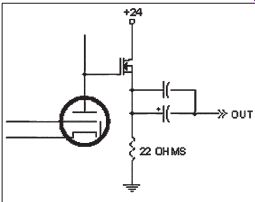
FIGURE 1: Alternative headphone amp circuit.
... BUF634, as well as introduce more second harmonic distortion. By itself, I agree that the SE FET circuit would likely sound better than a BUF634--but with the tube in front of it, the differences you hear will be small.
There's also the small matter of bias cur rent. If you kept 22 ohm in the drain, the circuit would draw about 450mA per channel, and dissipate about 5W in the drain resistor, as well as in the FET. Better get bigger resistors, heatsinks, and a hefty power supply.
And, by the way, you just added a bunch of money to the project! To be fair, you could raise the resistor to something on the order of 20 0 ohm and lower the current, and still drive most headphones.
You would compromise the capability of the amp to drive a reasonable voltage into low impedance headphones, though. A "much better result"?
I doubt it, but feel free to try it, especially if you use only headphones with 30 0 ohm or higher impedance.
As for adding 10dB of negative feedback around the circuit and changing to a common source configuration, if you want to do that, forget the tube and just use an op-amp. You'll completely lose the harmonic profile that I was trying to get--basically, you will remove the sound of the tube. Would it sound better ? Personally, I doubt whether I would like it, but maybe some people would. The constant-current diode on the tube plate (it is not an IC, rather a discrete FET de vice internally configured as a CCS) was used to allow the tube to swing near the power sup ply with low distortion. Of course, you could use a resistor as a plate load--but you would need to raise the power-supply voltage and/or live with a restricted voltage swing and more distortion. As to whether a resistive plate load or a CCS sounds better, that's a matter of de bate. I've been quite impressed with (god for bid!) solid-state CCS loads on the plate.
If you want an all-tube design, there are many possible implementations, including conventional designs that use transformer coupling from the plate, or circuits that use no output transformer (take a look at the out put impedances obtained in the article about high Gm tubes!) Again, that's not the point--these circuits all cost more, and most use high voltages and/or global feedback that I was trying to avoid.
Realize that everything is a compromise ? and keep an open mind!
VALVE ENTHUSIAST
I am nostalgic. Nostalgic for the good old days of Glass Audio magazine.
While reading some back issues of GA, I realized just what we valve enthusiasts lost when GA "married" your other publications. Take the Oct. '02 issue of aX, for example: just 2½ pages out of 72 are devoted to valve-related topics. We are not happy! Nevertheless, I shall continue sub scribing to aX for the foreseeable future, mainly so that I can purchase some of the excellent books your company reprints, even if they are very expensive over here--currently we pay $1.90 for $US1! The book Fundamentals of Radio Valve Technique is my current favorite.
Marvelous stuff! Terry Robinson Victoria, Australia Thanks for your comments and your kind words about Glass Audio. I think you might find another tube page in the October issue of aX if you look again. However, isn't there a hid den assumption in your accounting ? Our magazine today is about audio. All of audio. Does your system work without signal cables ? Isn't a report on cables relevant to your system ? Isn't Martin Colloms' advice about rooms relevant to someone who uses tubes in the system ? Do tube lovers never consider using a subwoofer ? Some readers have ventured out of playing an instrument with only one string, discovering the joys of building some devices which contain both tubes and op amps, or the de lights of building a speaker worth much more than they could possibly afford and designed by some of the best in the business. Time to drop the blinders and look at the rest of what audiophiles are being offered.
All in all, we believe the marriage is a success and is about the whole subject of audio.
If you check out a year of aX, you will find that our treatment of the three disciplines is about as balanced as we can make it. A teacher wouldn't pass or fail any student on the basis of one test or one term paper.
-E.T.D.
THE AMP REVIEW
Regarding the review of the S-5 Electronics Amplifier in the Nov. '02 issue (p. 47), using four triode/pentode tubes originally designed for television vertical deflection amplification service to make a stereo, push-pull amplifier is very clever. As to pentode, push-pull amplifier tubes operating in Class-A or -A1, I find that generally output power is equal to the allowable plate dissipation;
i.e., 6L6s with allowable plate dissipation of 30W can produce 30W. The RCA tube manual covers triode/pentode tubes in tended for vertical deflection amplification service: 5FV8 = 6FV8 and 10C8.
These have allowable plate dissipation values of about 2.2W, so that by the relationship mentioned previously, only about 2.2W output can be expected, but 8W is claimed, and at 1000Hz, with a favorable load, 8W was achieved, but at a horrendous distortion level.
What I am leading up to is to suggest that, perhaps, the allowable plate dissipation is being exceeded, that this excessive heat is contributing to the sockets scorching and melting, and that this will result not only in melting sockets, but with very short tube life as well.
This suggests the questions: Are re placement tubes readily available, where can they be obtained, and how much do they cost ? This amplifier has very high levels of frequency and amplitude distortion ? this is objective fact. Duncan and Nancy's opinion that it nevertheless sounds pretty good is their subjective assessment. Is it fair to conclude that either they can't hear those distortion products, or that they hear them, but find them pleasing ? I think that their recommendation of this amp can be ignored at least until other amps in this price range are also tested and auditioned.
D.J. Meraner
Duncan and Nancy MacArthur respond:
As we mentioned in the review, tube amplifiers sometimes measure poorly but receive good reviews for sound. This observation is unique neither to us nor to aX.
"ELEPHANTS" CONTINUED
Paul E. Davis' letter (Nov. 2002 aX, p. 61) about audio "elephants" get ting in the way of good speaker design prompts me to add a few more "elephants" (notes of caution) to his three.
Elephant #0 should be "what the heck are you measuring ?" In his case, he is measuring with an SPL meter in his room. This is OK in some rough sense, but the danger is that it combines the direct sound with the reflected sound, and your ears/brain perceive those differently.
At a recent Audio Engineering Society meeting in L.A., Jamie Anderson told a funny story about touring with the Grateful Dead back when FFTs were very new to pro-sound. They stuck a mike in the air, made a measurement, meticulously EQd every narrow peak and dip, and wondered why it sounded bad. The retro-spectoscope revealed that they were measuring the effects of reflections mixed in with the direct sound.
In fact, they should have been EQing only to the direct sound's response.
This is why speaker designers build anechoic chambers, or buy time-gating equipment, or employ one of Vance Dickason's favorite methods by "hauling everything outside," as Paul Davis puts it. If you can't measure without the reflections, you almost might as well not measure at all (except perhaps the bass region). Elephant #4 I'd call "how good is your equipment": in this case, the Radio Shack SPL meter. I'm not sure about the current one, but my old one shows a large upper midrange response peak in the owner's manual, even in the "flat" mode! In any case, newbies to speaker building should definitely "beware of elephants"--and if you can't measure your driver's actual impedance and quasi-anechoic frequency response, do yourself a favor and buy a kit.
Eric Guarin
TUBE SOURCE
Where can I buy the Russian 6S17K-V tube mentioned in Eric Barbour's "A Planar-Triode Phono Preamp" (Nov. '01 aX, p. 18)
The supplier listed claims he never had the tubes and can't get them.
Richard P. Robinson
Eric Barbour responds:
There is a new dealer of Russian tubes, Peter Zarytov, with a website: http://gstubes.com.
He claims to have access to 6S17K-Vs, under the original number 6C17K-B.
If he can't help, I don't know what else to suggest. Many of the surplus Russian electronic dealers have gone out of business in the past year. All I could suggest is to write to New Sensor and ask them to import some of these tubes. Perhaps if enough people do so, they will take action.
VIVA LA RESISTANCE!
Double thanks for printing two of my letters in the Oct. issue--especially the one about the good, cheap MCM tweeter (pp. 62-63). I can imagine more than one of your advertisers being unhappy about seeing such a thing in your magazine--but you printed it anyway! Viva La Resistance! And what is La Resistance-- It's those who use and trust their ears. It's those who build their own stuff--not just to save money but because there is a kind of faith that there is something better:
something you can't buy off the shelf. It's my belief that this is why a mag like Stereophile is doomed. Their premise is if you spend more money, you can reach musical ecstasy (do I sound like the late Harvey Rosenberg ?).
This is essentially not true. You're only going to get as much out of your system as you put into it. This isn't to say money isn't part of the equation--it is, but it's the consciousness of the builder that matters more. Magic isn't something you buy--it's something you do.
Rick Bergman Missoula, Mont.
HORN FOR GUITAR
I have some questions concerning the DR10a horn by Bill Fitzmaurice (June 2002 aX, p. 16). Can I use the Eminence Beta 10 transducer in this horn ? How is the compression chamber be hind the loudspeaker calculated ? Is this a bass-reflex system or a mixture of bass reflex and horn ? I hope you can answer these questions, because I am planning to build this horn for my guitar.
Sebastian Braun
Bill Fitzmaurice responds:
The Beta 10 will work, since its parameters are well within the preferred limits. I assume that purchasing a Carvin PS10 from California is not the best route for you in Germany.
But if Eminence products are available to you, I'd go with the Gamma 10, whose higher fs will provide smoother response.
The woofer chamber, being vented, is not a compression chamber. The system is a combination of horn and bass reflex. The volume of the chamber was not calculated. My designs are 90% empirical, 10% formulaic.
I choose a target cabinet volume, design the largest horn possible to fit inside of it, and what is left over becomes the rear chamber.
This unorthodox method works because most of the performance is derived from the horn section, and the high fs low Q MI drivers used are designed for relatively small enclosure volumes, anyway.
Your intention to use a DR10a for a guitar brings up questions from me. Is this for electric guitar ? If so, the DR10a, or any horn loaded cab, is probably not what you need.
Classic electric guitar tones are heavily colored and distorted, and are best achieved with either very small infinite baffle cabinets or open back cabinets.
Acoustic guitar is another matter, because that instrument is best projected through a fairly clean wideband speaker, which the DR10a definitely is. However, the vented chamber of the DR10a extends bass response of the cabinet to well below the passband of the horn, which is great for electric bass, key board, or PA, but unnecessary for guitar. If you intend your DR10a strictly for acoustic guitar, you'll get better mid-bass response by not using any ducts, thus making the rear chamber a compression chamber. Response below 80Hz will suffer, but that matters not, since the guitar doesn't go down there anyway, and response around 125Hz will be better.
KIT WANTED
I've just read the November 2002 issue of aX, featuring a valve/solid state headphone amp project ("Build a Low-Voltage Tube Hybrid Headphone/Line Amp," pp. 20-31). This is just what we have been looking for! Unfortunately, despite searching through some Australian electronics catalogs, some of the specialized parts seem to be unavailable in Australia. It would be good if this project could be offered as a kit.
Terry Robinson Victoria, Australia
HELP WANTED
I recently found a product named Bozak model #N-10102A that appears to be a crossover for two tweeters (model #B-200Y) on a frame that held a 12” woofer, which is missing. The two midrange/bass units are 5” (model #B 209B). All drivers are 8”. My question is what year was it manufactured, and what are the crossover frequency, the wattage of the speakers, and perhaps the cost of the product at the time ? (The label reads R.T. Bozak MFG. CO., S. Norwalk Conn., USA.) David Mozingo 2669 NC 102-E Ayden, NC 28513
Readers with information on this topic are encouraged to respond directly to the letter writer at the address provided.
-Eds.
Book Review
Master Handbook of Acoustics, Fourth Edition
Reviewed by Duncan MacArthur
Master Handbook of Acoustics, Fourth Edition; F. Alton Everest. McGraw-Hill, 2001, 615 pages, ISBN 0-07-136097-2, $34.95.
The word acoustics means different things to different people. To a stadium designer, acoustics is about ensuring clear vocal reproduction at every seat.
Concert halls are usually smaller, but the designer must ensure that the en tire musical spectrum is reproduced at each seat.
To the recording engineer, acoustics means the effects of the studio on the sound produced by musicians as well as the reproduction of sound in the control room. Audio enthusiasts may believe that the effects of smaller, often multipurpose, rooms on music reproduction are most important. All these and more are acoustics, with the result that any single book, even a lengthy one, cannot cover everything in detail.
ACOUSTICS
The detailed study of acoustics can also be mathematically complex. Fortunately, this level of detail, although critical to the professional acoustical engineer, is not essential to understand basic listening room acoustics. In his Master Handbook of Acoustics, Mr. Everest successfully keeps the mathematics to the absolute minimum required. He uses many graphs and tables, a few photographs, and a minimal number of formulas to describe various phenomena. Readers with mathematical back grounds might prefer more detail, but even they will appreciate explanations that don't immediately resort to arcane mathematics.
In this volume Mr. Everest concentrates on the acoustics of small rooms, such as home listening rooms and studios. He also discusses the principles behind-and the effects of-various commercial acoustical tools as well as a number of "home-built" alternatives.
Additional short chapters cover scientific fundamentals and advanced techniques. Finally, the author includes extensive references to further reading and primary source material.
In an attempt to give a flavor of a thick book in a short review, I have di vided the chapters into four groups. In the early chapters, Everest covers general introductory material, the small amount of required mathematics, and several topics primarily of scientific interest. Next comes a group of chapters with some content useful to the home listener mixed with other material. A number of chapters deal explicitly with recording studios and techniques. Finally, six chapters covering absorption, diffusion, and listening room acoustics contain material highly useful to the audio enthusiast.
INTRODUCTORY MATERIAL (1, 2, 3, 4, 5, 11, AND 12)
The first five chapters contain introductory material required to understand the rest of the book. No prior knowledge of acoustics or higher mathematics is needed to understand these chapters. The more experienced reader may prefer to skip these chapters the first time through, but can refer to them at need if a more advanced topic doesn't make sense.
Chapter 1, "Fundamentals of Sound," introduces the basic concepts of sine waves, wave propagation, and the relationship between frequency and wave length. For the first time (of many throughout the book) graphical explanations supplement the mathematical formulas. The concepts of harmonics, octaves, phase, and spectrum are introduced, and this chapter concludes with a short description of electrical analogies.
Since the response of the human ear is intrinsically logarithmic, some discussion of logarithms, exponentials, and scientific notation is required even in a fundamentally non-mathematical book. This material, along with the concept of acoustic power and numerous examples, is covered in Chapter 2, "Sound Levels and the Decibel." The concepts of subjective loudness as well as the relationships between loudness and frequency and pitch and frequency are introduced in Chapter 3,
"The Ear and the Perception of Sound." This chapter introduces Fletcher/Mun son-type response curves and explains the function of a loudness (as opposed to volume) control. The description of the precedence or Haas effect is particularly important for future discussions of loudspeaker placement.
Chapters 4 and 5, "Sound Waves in the Free Field" and "Speech, Music and Noise," touch briefly on free-field relationships and sources of sounds.
I was particularly glad to see that Everest has included two charts to which I refer frequently: "Power of Musical Sources" (Table 5.1) and "The Audible Frequency Range of Various Mu sical Instruments . . ." (Fig. 5-11). He describes the distinction between "white" and "pink" noise as well as the concept of musical distortion.
The concepts of "Diffraction" and "Refraction" of sound introduced in Chapters 11 and 12 are primarily of scientific interest. Other than the introduction to diffraction around speaker cabinets in Chapter 11, this material appears to be included for completeness and is not necessary to understanding the remainder of the book.
CHAPTERS OF MORE INTEREST (6, 7, 8, 10, 24, 25, 26, 27, AND 28) A number of chapters in the Master Handbook of Acoustics contain some useful material along with material that is not directly applicable to home listening. The usefulness of this group of chapters depends greatly on the reader's personal definition of acoustics.
Chapter 6, "Analog and Digital Signal Processing," provides a very brief introduction to a topic that probably will be a key development in the next decade. At this time, signal processing (especially digital) offers a taste (albeit an expensive one) of good things to come.
Reverberation, as discussed in Chapter 7, is one of the key ingredients in concert hall-and other acoustic space- design. Understanding the concepts of reverberation decay time, variations with frequency and position, and the Sabine equation is important for hall design. Practical advice on these subjects is reserved for later chapters.
Control of externally generated noise-whether from the neighbor's lawnmower or from your own HVAC system-is a constant concern for many music listeners. For most of us the most common "solutions" are to "grin and bear it" or "listen some other time." In Chapter 8, Everest provides some ideas for improving this situation, but not a detailed discussion.
Chapter 10, "Reflection of Sound," gives some information on reflection of sound waves off various shapes. Many of the distortions generated by these re flections are discussed in Chapter 25.
Although Chapter 10 includes many examples of problems, solutions are mostly left for later chapters.
Adjustable acoustics is potentially important to the home listener, especially when the listening room does double duty as living room or family room; however, Chapter 24 is oriented more towards recording studios than towards listening rooms. This chapter also reads a bit like an advertisement for ASC and RPG products.
As with Chapter 6, Chapters 26, 27, and 28 offer tantalizing glimpses of advanced technologies. These chapters discuss "Room Acoustics Measurement Software," "Room Optimization," and "Desktop Auralization," respectively.
As you might expect in an overview treatment, all three chapters consist mostly of glowing descriptions of single commercial products. Rather than viewing this as advertising, I interpret these as examples of very impressive technologies that are becoming avail able (for a price). These technologies are currently more in the realm of acoustic professionals than hobbyists.
RECORDING ORIENTED (17, 20, 21, 22, AND 23)
A number of chapters in the Master Handbook of Acoustics are specifically aimed at recording studio design and technique. Since the acoustics of studios and living rooms are related, some elements of these chapters may be of interest to the home listener. In particular, many of the photographs, although specifically of studio applications, will also interest the home listener.
Chapter 17, "Comb Filter Effects," discusses the effect of the interference be tween two sound sources. Although this is primarily microphone oriented, Mr.
Everest also discusses interference be tween two stereo speakers and between drivers in individual speaker systems.
"Quiet Air for the Studio," as discussed in Chapter 18, is a practical continuation of the earlier chapter (8) on noise. Many of the techniques are potentially applicable to home listening rooms; however, few of us have the opportunity to design and build a room specifically for listening.
Chapters 20 and 21, "Acoustics of the Small Recording Studio" and
"Acoustics of the Control Room," would be more interesting if they didn't immediately follow Chapter 19, which discusses acoustics of the listening room.
As it is, Chapter 20 covers much of the same material from a recording studio point of view with more emphasis on diffusion and noise control. Chapter 21 discusses the time delay gap (first mentioned in Chapter 3) as well as LEDE (Live End Dead End) techniques and more uses of RPG products. Everest includes numerous photographs of actual implementations.
The chapter on "Acoustics for Multi Track Recording" (#22) will be of interest to studio designers. Chapter 23, "Audio/Video Tech Room and Voice Over Recording," contains another discussion of room modes (the most complete is in Chapters 15 and 19) and continues the discussion of Chapters 20 and 21.
MOST USEFUL FOR HOME LISTENING (9, 13, 14, 15, 16, AND 19)
I've saved the best for last. The Master Handbook of Acoustics contains six chapters that are indispensable for understanding listening room problems, potential solutions, and commercial implementations of these solutions.
The interaction between the listening room and sound reproduction is often misunderstood. Among other things, these chapters explain why different rooms sound different and what you can do about it. Even if you have no interest in building room treatments, this material helps immeasurably in understanding the commercial products that are available.
In Chapter 9, "Absorption of Sound," the author covers a range of topics including evaluation of absorption, sheet absorbers (e.g., foam, fiberglass, drapes, and carpet), and bass absorbers such as traps, diaphragms, and Helmholtz resonators. This chapter is also the place to look for a thorough description of poly cylindrical absorbers or "polys." In addition to containing an enormous amount of DIY information, this chapter pro vides an extremely useful explanation of the effects of commercial products. I would buy the Master Handbook of Acoustics for this chapter alone.
Room modes and their relationship to room dimensions are one of the most important acoustic issues for the home listener. Chapter 13, somewhat confusingly titled "Diffusion of Sound," addresses these questions as well as the effects of room shape and general sound field issues. "Modal Resonances in Enclosed Spaces" are revisited in Chapter 15 with emphasis on calculating modes in rectangular rooms.
In Chapter 19, Everest discusses room modes yet again with emphasis on solutions and bass traps. Chapter 19 also includes a discussion of reflections and midrange clarity. Although the material on room modes is spread among three chapters (and more), the complete discussion is quite thorough. This set of three chapters is an excellent introduction to the concept of room modes.
One significant advance in acoustics in the last couple of decades has been the application of diffraction gratings to sound waves. Chapter 14, "The Schroeder Diffusor," traces the history of grating-based diffusors from the original Schroeder models through the more re cent quadratic residue and primitive root designs. This chapter concludes with a huge amount of design information, but the description of commercial systems is somewhat "RPG-centric." Finally, in Chapter 16, "Sound Re flections in Enclosed Spaces," the discussion moves away from bass characteristics of listening rooms to reflection effects in the midrange. Topics covered here include echoes, imaging, and spaciousness.
CONCLUSION
If you're looking for a single introduction to acoustics that doesn't require much mathematics, it's hard to see how you could go wrong with the Master Handbook of Acoustics. As I mentioned earlier, its very breadth of coverage means that the coverage on any given subject may not be deep. In such cases, the references to other material may be more important than the text itself. However, I highly recommend the Master Handbook for basic explanations of numerous acoustic effects and techniques. This new, larger edition is a worthwhile addition to your library even if (or per haps especially if) you already own an earlier edition.
Audio Aid
A 1¢ Diffraction Detector
No matter how well you plan your speaker design, you never really close in on your desired results without testing and measurement. Here's a test you can use that doesn't even require the use of dangerous electricity.
When you listen to pink noise over loudspeakers, you'll often hear a "voice" that sounds like a resonance. In the literature, these resonances are often corrected with electrical filters-- resistors, capacitors, and inductors in the crossover network, or with active equalizers. I found a different way to at tack some of these resonances. If this method has ever been published, I've never read it.
When I was working with an old Audax HIF13J mid-woofer from the mid-1970s, pink noise sounded as though it was coming from a cat's mouth. I found and corrected the problem using an extremely inexpensive testing device--a plastic soda straw, free with your drink at your local fast food restaurant.
Try this. Before you even go to get your straw, blow on the palm of your hand. Then blow on your fingertips, and then on the edges of the magazine pages. If you're wearing a shirt, blow on that. They all sound different, don't they ? The difference is diffraction and turbulence.
The next step is to take your soda straw and go on a search and destroy mission. Blow on the face of your speaker driver, the surround, gasket, and basket. Blow on the edge between the driver and baffle. Blow on the cabinet corners--even rounded ones. Every time you hear turbulence, there's an opportunity to improve your sound.
I found with the old Audax driver that blowing on the square-profile cork gasket produced a rushing sound that had the same cat's mouth character as the pink noise. I molded some modeling clay around the gasket to smooth the profile, and found that I had also smoothed the sound. The modeling clay soon fell off, but I could always apply this solution to correct the diffraction noise in a more permanent material.
Granted, minimizing diffraction is nothing new. It was all the rage a generation ago, and since then many drivers have smooth, non-diffracting edges.
You now find even budget systems with drivers mounted in molded baffles with smooth transitions or shallow horn-like exit profiles.
I don't know what methods the manufacturers use to find and correct dif fraction, but this is an easy and inexpensive tool to help you do the same thing. You can find the causes of dif fraction noise, and try out different baffle shapes in soft moldable materials before you take the time and expense of sculpting a baffle mold or investing in router bits that may or may not give you the results you're hoping for. You can also test different fabrics, foams, and other absorbing baffle treatments while you're still in the fabric store. All you have to do is blow.
Mark Hotchkiss; Mabelvale, Ark.
Current-Regulated Heater Supplies
By Michael Kornacker
In my article, "Direct-Coupled Circuits Need Regulated DC Heaters" (March '01 aX, p. 86), I discussed the need to regulate the heater voltage supply in directly coupled DC tube amplifiers to en sure stable operation. I would like to make some additional comments and talk about regulator circuits for tube heaters in regards to current supply.
CURRENT vs VOLTAGE REGULATION
Truth be told, a constant applied volt age, as in a regulated supply to a tube's heaters, does not guarantee a constant current drawn by those heaters. Be cause electron emission between the cathode and the plate of a tube is more closely tied with the thermal effect of electron current flow in the heater, a heater current regulator would be more efficient at controlling the operating point than heater voltage regulation.
1. Although a voltage regulated supply will be superior to an unregulated sup ply in this respect, best results would be obtained with current regulation.
With voltage regulation, any resistance, such as too small a hook-up wire, corroded tube pins, cold solder connections, or bad socket contacts, will cause voltage drops, and the heaters will not receive their fair share of current. With current regulation, after the current is set it will remain fixed and all these detrimental factors become irrelevant.
2. Current regulation also adds longer heater life due to its soft-start character.
In a normal situation, when power is applied, a cold heater acts like a short circuit drawing a huge in-rush current flow before it heats up. Every time you turn it on, the accumulation of the filament's transitions from ambient to white-hot eventually weakens it. Do it one too many times, and the tube finally burns out. A current regulator will limit this current spike, even when cold, to the heater's normal steady-state current draw and as a result prolong tube life.
3. When an incandescent lamp is turned on (which is basically the same as the heater in a vacuum tube), its filament can draw up to 18 times its normal operating current. Even after 5ms, cur rent flow could still be up to five times normal. So, as the filament heats and light is emitted, its resistance increases and the peak current decays "quasi-exponentially" to its normal rate.
4. You have seen that room light bulbs can burn out with a flash when you first flip on the wall switch, usually never after the lamp has been on for a while.
This shows that the high mortality rate of lamps--and, thus, tube heaters--is caused by being constantly over stressed at turn-on. Current regulation would eliminate this problem and save money.
THE CIRCUIT
With today's technology, implementing current regulation is as easy as voltage regulation. Figure 1 is an LM317 regulator chip configured as a current regulator. The input voltage to the LM317 must be greater than the required out put voltage for the load by about one and a half times. The current limiting resistor R is equal to 1.25 divided by the total load current of the heaters. The wattage of R should be greater than the product of the above quantities.
When you power up the regulator circuit, check for both the required cur rent through the heaters and for the voltage across the heaters. You may need to fine tune R to obtain the proper values because the resistance R calculated is rarely the actual value required.
In my own amplifier ("Eico HF-86," GA 4/99, p. 68), I have two 12DW7s rewired for 12.6V heaters, which draw a total of 0.3A. That makes R equal to 4.17 ohm at 2W. The amplifier's trans former has two 6.3V secondaries--one for the HV rectifier tube, which was un used since I replaced the tube with semiconductor diodes, and the other for the rest of the tubes (the two 12DW7s and four power output tubes).
I separated the 12DW7 heaters from the rest so that I could power them with DC. To obtain the required DC voltage, I connected the two secondaries in series and full-wave-bridge-rectified and filtered it to obtain about 17V. I connected this to the LM317 current regulator, and then to the heaters. I also needed to heatsink the LM317.
After adjusting the value of R for 12.6V and 0.3A at the heaters, everything worked beautifully. I ended up using a 4.3 ohm 2W (meas. 4.4 ohm) in parallel with a 62 ohm half watt (meas. 66 ohm). To my surprise, I found that there was no residual ripple voltage across the heaters as there was across the filter cap. Apparently the current regulator removes the ripple just like its voltage regulator counterpart.
Using a heater current regulator should provide the utmost in stable operation of vacuum tubes, regardless of whether it is direct coupled or not. This will also have the benefit of an automatic soft-start and reduce the possibility of hum being induced into the cathode circuit and the rest of your amplifier.
REFERENCES
1. Regulated Power Supplies, Irving M. Gottlieb, 4th Edition, Tab Books, 1992, p. 15.
2. Ibid., p. 40.
3. Ibid., p. 41.
4. "MOSPOWER Application Notes," Siliconix Inc., Rudy Severns, Editor in Chief, Santa Clara, Calif., 1984, p. 6-82, 83.
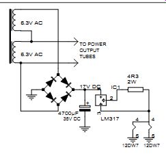
FIGURE 1: The LM317 current regulator circuit used for the preamp tubes of the amplifier.
-------
Also see:
PRODUCT REVIEW: BUDGET PHONO PREAMPS---Here's a survey of some low-cost phono preamps. Find out which one is right for you.