A HYBRID STEREO $90 CONTROL---With its low cost and simple circuit architecture, this high-quality control unit is one you can easily add to your audio system.
-------
For a modest cost, this control unit offers lifelike, concert-hall performance, featuring cascaded FETs in the phono section and high perveance tubes in the line amplifier section.
By Joseph Norwood Still
This hybrid-design control unit (Photo 1) has a plug-in-the-wall 24V AC power transformer ($5.50), a chassis-mounted trans former ($5.99), a vacuum tube line amplifier, and an optional FET phono amplifier. The wall-wart power transformer is remotely located from the control unit chassis to ensure low noise operation. This transformer provides power to operate a 25V AC (input) to 120V AC (output) chassis-mounted power trans former and a full-wave, bridge-rectifier to furnish power to the series-connect ed filaments of the line amplifier. The 120V AC output "feeds" a full-wave, volt age-doubler, bridge-rectifier and pro vides 220V DC output.
Because the wall-wart transformer delivers most of the power to operate the control unit, the undesired magnetic noise of this transformer is isolated from the control unit chassis. The chassis-mounted power transformer operates at a low power level and thus generates a low level of magnetic noise.
The control unit (Photo 2) has a two section, six-position selector switch.
Five positions are used for line-level operation, while you can use the sixth position for a phono amplifier. Separate right- and left-channel volume controls are used, instead of a balance control, to prevent crossover distortion. The DPST power switch turns the control unit and remote power amplifier on or off.
--------------
ABOUT THE AUTHOR
Joseph Norwood Still, retired from the electronics industry, is designing affordable high-quality audio amplifiers for the dedicated audiophile. This is a hobby he thoroughly enjoys and is especially rewarded with many pleasant interchanges with dedicated, resourceful audiophiles. He resides in Bel Air, Md.
----------------
The control unit operating in the line-level or phono mode with volume control "full-on" is "dead-quiet," and you cannot detect noise with your ears inches away from the speakers. The realism of sound reproduction of the control unit with the phono and line-level amplifiers operating is excellent. Note: The control unit features two entirely different designs (Table 1). The first features a traditional design using paralleled 5687s with a voltage gain of eight. The second design features the 12B4A with a voltage gain of 2.4. When operating in the CD, phono, or tuner modes, the 12B4A's low voltage gain is able to drive a power amplifier to its full output. The output signal of my phono/line amplifier is greater than the output signal of a Sony CD, Model CA9ES when "fed" through the line amplifier.
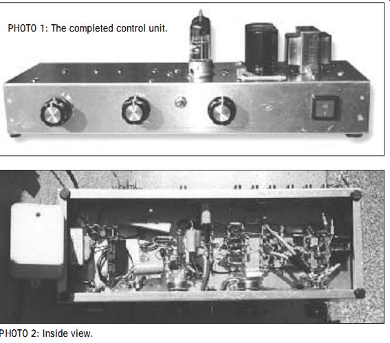
PHOTO 1: The completed control unit. PHOTO 2: Inside view.
The use of the 12B4A and its low volt age gain provides a more realistic transparent sound, lower distortion, and much higher headroom from signal overload than the more traditional 5687. This gives substantial "head room" at the input and output of the tube for reproduction of music peaks with no danger of clipping. The low amplification factor, low plate resistance, and high cathode bias (16V DC) make the 12B4A tube a great line amplifier and explains its excellent performance.
I have provided separate descriptions for the 5687 and 12B4A line amplifier designs, so you can opt to build the line amplifier that best matches your own preference and audio system.
LINE AMPLIFIER (USING THE 5687)
The line amplifier (Fig. 1) uses two 5687 tubes whose heaters are connected in a series string configuration. The heaters are operated at 20V DC, supplied by a well-filtered, full-wave bridge-rectifier.
The plates of the 5687 are operated from a supply voltage of +220V DC/ 10mA. The heater of the 5687 is operated at a reduced voltage of 10V DC to obtain low-noise operation from this stage. The normal heater power for the 5687 is excessive, operating at the same power level as a 6L6.
The circuit of the line amplifier is simple and straightforward. The 5687 is especially suited for use as a line amplifier with its 6V DC cathode bias and its 1.1% distortion at 20V RMS output. This provides considerable headroom at both the input and the output of the tube and ensures no clipping will occur during reproduction of music peaks.
The noise of the line amplifier is 0.3mV with volume control (R1) full on and the input open, non shorted. (I measured the noise with a digital multi meter (DMM), Radio Shack, 22-168A.) All noise and ripple measurements throughout this article use a DMM with shielded test leads. The distortion from 40Hz to 20kHz of the line level stage is typically 0.28% at 5V RMS output, while at 3V RMS it is 0.18% (see Table 2 for more distortion data).
The frequency response of the line amplifier is flat from 10Hz to 20kHz; feeding a 6' audio cable (Radio Shack 15-1505), the frequency response is flat from 10Hz to 18kHz. The high-frequency operation of the line amplifier is enhanced by paralleling capacitors C1 (0.47µF) and C2 (.047µF). The resistors R2, R5, and R6 are added to en sure stability. The 22 k-O plate resistor and 1.2 k-O cathode resistor provide a low distortion output. A separate 100k volume control is used for each stereo channel to ensure maxi mum stereo separation and minimum crossover distortion.
LINE AMPLIFIER (USING THE 12B4A)
The line amplifier (Fig. 2) uses high-perveance 12B4A tubes whose heaters are connected in a series string configuration. The heaters are operated at 24V DC, supplied by a well-filtered, full wave, bridge rectifier. The plates of the 12B4A are operated from a supply voltage of +220V DC/10mA. The circuit of the line amplifier is simple and straightforward, and the excel lent performance is related to the out standing features of the 12B4A tube in this application. It has a plate curve that jumps straight up from the base line and is very linear, as its low distortion characteristics verify. You can apply the axiom, a straight wire with gain, to this tube because of its low voltage gain.
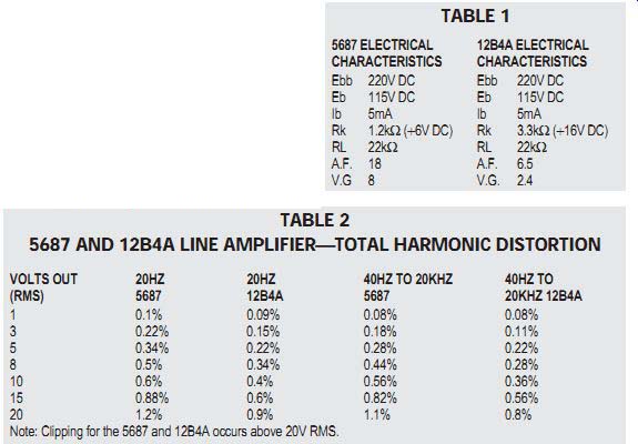
TABLE 1
5687 ELECTRICAL 12B4A ELECTRICAL CHARACTERISTICS
CHARACTERISTICS
Ebb 220V DC Ebb 220V DC Eb 115V DC Eb 115V DC Ib 5mA Ib 5mA Rk 1.2 k-O(+6V DC) Rk 3.3 k-O(+16V DC) RL 22 k-O RL 22 k-O A.F. 18 A.F. 6.5 V.G 8 V.G. 2.4
-----------------
TABLE 2
5687 AND 12B4A LINE AMPLIFIER ?TOTAL HARMONIC DISTORTION VOLTS OUT 20HZ
20HZ 40HZ TO 20KHZ 40HZ TO (RMS) 5687 12B4A 5687 20KHZ 12B4A 1 0.1% 0.09% 0.08% 0.08% 3 0.22% 0.15% 0.18% 0.11% 5 0.34% 0.22% 0.28% 0.22% 8 0.5% 0.34% 0.44% 0.28% 10 0.6% 0.4% 0.56% 0.36% 15 0.88% 0.6% 0.82% 0.56% 20 1.2% 0.9% 1.1% 0.8% Note: Clipping for the 5687 and 12B4A occurs above 20V RMS.
-------------------
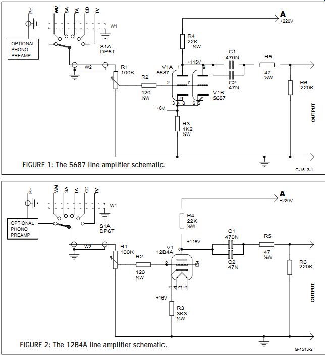
FIGURE 1: The 5687 line amplifier schematic.
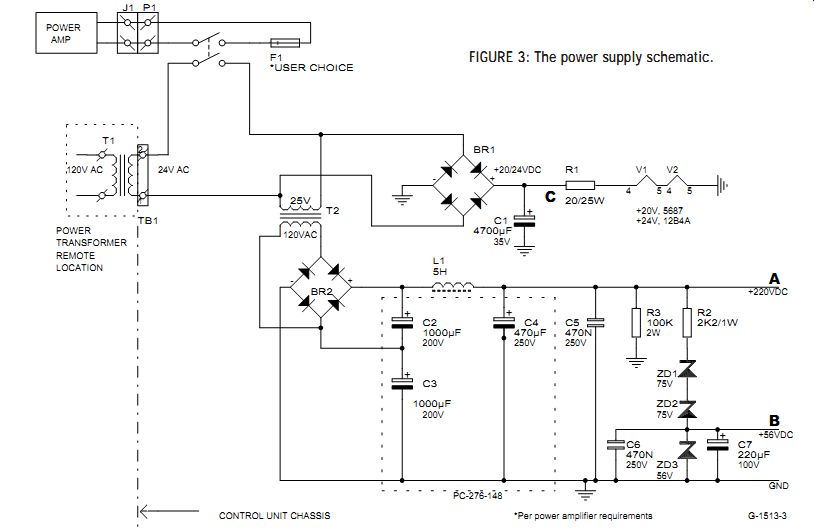
FIGURE 2: The 12B4A line amplifier schematic.
FIGURE 3: The power supply schematic.
In my opinion, the sonic performance of the 12B4A as a line amplifier is superior to the 5687, 6SN7, or 6H30. The 12B4A is especially suited for use as a line amplifier with its 16V DC cathode bias and its 0.8% distortion at 20V RMS output. This provides incredible head room at both the input and the output of the tube and ensures no clipping will occur during reproduction of music peaks. The use of this tube will provide total transparency at the line-level stage and will permit you to concentrate on the power amplifier and the input stage preceding the line amplifier for further refinement of your audio system. The noise of the line amplifier is
0.1mV with volume control (R1) full on and the input open, non-shorted. The distortion from 40Hz to 20kHz of the line-level stage is typically 0.22% at 5V RMS output, while at 3V RMS it is less than 0.11% (see Table 2 for more distortion data).
The frequency response of the line amplifier is flat from 10Hz to 20kHz; feeding a 6' audio cable (Radio Shack 15-1505), the frequency response is flat from 10Hz to 18kHz. The high-frequency operation of the line amplifier is enhanced by paralleling capacitors C1 (0.47µF) and C2 (.047µF). The resistors R2, R5, and R6 are added to ensure stability. The 22 k-O plate resistor and 3.3 k-O cathode resistor provide a low distortion output. A separate 100k volume control is used for each stereo channel to ensure maxi mum stereo separation and minimum crossover distortion.
Note: If you build the phono amplifier, I recommend you use the 12B4A as a line amplifier, because its low voltage gain is more compatible with the high output of the phono amplifier.
POWER SUPPLY
The power supply (Fig. 3) consists of a wall-wart 120V AC to 24V AC trans former, built-in overload protection.
------------- TABLE 3
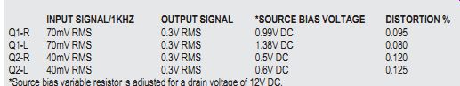
DRAIN SUPPLY VOLTAGE 56V DC, DRAIN LOAD RESISTOR 39K, DRAIN VOLTAGE 12V DC
INPUT SIGNAL/1KHZ OUTPUT SIGNAL *SOURCE BIAS VOLTAGE DISTORTION %
Q1-R 70mV RMS 0.3V RMS 0.99V DC 0.095
Q1-L 70mV RMS 0.3V RMS 1.38V DC 0.080
Q2-R 40mV RMS 0.3V RMS 0.5V DC 0.120
Q2-L 40mV RMS 0.3V RMS 0.6V DC 0.125
Source bias variable resistor is adjusted for a drain voltage of 12V DC.
--------------------------
The wall-wart secondary is rated at 830mA/24V AC, which is conservatively rated to furnish power to operate the FETs and 5687/12B4As. The wall-wart 24V AC output voltage feeds a full-wave, bridge-rectifier that provides 20/24V DC output to the heaters of series-connect ed 5687/12B4As. It is filtered by capacitor C1, and resistor R2 (2 0 ohm) is a voltage dropper device. The large value of capacitor C1 reduces the noise voltage to 0.002V AC at the 20/24V DC output of resistor R2.
The 24V AC output of the wall-wart also feeds the 25V AC winding of chassis-mounted transformer T2. The 120V AC output of transformer T2 feeds a full-wave bridge (BR-2), voltage-doubler rectifier. Voltage doubling is accomplished by capacitors C2 and C3. The choke L1 diminishes the switching transients that occur during the rectification process.
Capacitor C4 provides additional filtering and a low noise of 0.004V AC at the +220V DC output. (I measured the noise with a 2µF Mylar capacitor connected in series with the DMM shielded test leads). The +56V DC (.001V AC noise) to operate the phono amplifier is obtained at the junction of zener diodes ZD-2 and ZD-3. Capacitor C7 filters the +56V DC output. Capacitors C5 and C6 eliminate AC spikes.
PHONO AMPLIFIER
FET's Widely Variable Electrical Characteristics Important: When building FET amplifiers, it is essential to establish an environment conducive to minimum handling (static electricity) and heat con tact of the FET. To ensure this occurs, install transistor sockets for the FETs Q1 and Q2. It is not necessary to have the socket mounted in the chassis--you may solder stiff wires to the socket wires, which you then solder to their respective components/terminal strips.
Note: For audio applications, the primary variable electrical characteristics of the FET is the bias control point. A variation in the bias control point affects the drain current and thus the voltage presented to the drain via the drain load resistor. This, of course, affects the distortion.
The obvious solution is to install a variable resistor in the source circuit and adjust the resistor to obtain the de sired drain voltage (or more precisely, the drain voltage shown on the schematic). The phono amplifier presented here uses a variable resistor in each source element of the four FET stages. The vari able resistors (R3 and R9) are pre-set to 1 k-O before they are connected in the circuit to avoid damaging FETs Q1 and Q2.
-----------------
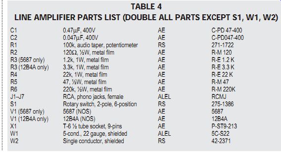
TABLE 4
LINE AMPLIFIER PARTS LIST (DOUBLE ALL PARTS EXCEPT S1, W1, W2)
C1 0.47µF, 400V AE C-PD 47-400 C2 0.047µF, 400V AE C-PD047-400 R1 100k, audio taper, potentiometer RS 271-1722 R2 12 0 ohm, ½W, metal film AE R-M 120 R3 (5687 only) 1.2k, 1W, metal film AE R-E 1.2 K R3 (12B4A only) 3.3k, 1W, metal film AE R-E 3.3 K R4 22k, 1W, metal film AE R-E 22 K R5 47, ½W, metal film AE R-M 47 R6 220k, ½W, metal film AE R-M 220K J1-J7 RCA, phono jacks, female ALEL RCMJ S1 Rotary switch, 2-pole, 6-position RS 275-1386 V1 (5687 only) 5687 (NOS) AE 5687 V1 (12B4A only) 12B4A (NOS) AE 12B4A X1 T-6 ½ tube socket, 9-pins AE P-ST9-213 W1 5-cond., 22 gauge, shielded ALEL 5C-S22 W2 Single conductor, shielded RS 42-2371
------------------------
Of interest: The commercial manufacturer of phono amplifiers requests that hand-selected FETs have tightly controlled electrical characteristics and pay a premium price for this service.
They also are required to purchase a minimum quantity of 100 FETs. When the FETs are received in-house, they are again pre-tested to ensure the de sired conformity and electrical tolerance characteristics are obtained, be fore they are finally wired into their respective circuit.
CIRCUIT ANALYSIS
The phono amplifier (Fig. 4) uses readily available NTE459 FETs ($2.66). It features a non-feedback design with a passive RIAA network. The noise is less than 0.1mV, and sensitivity is 0.003V for 1.25V RMS output at 500Hz or 0.9V RMS at 1kHz.
The distortion of the first-stage FET is less than 0.12% from 20Hz to 20kHz with the input signal adjusted from 0.3V RMS output at all measured frequencies. The distortion of the second stage FET is less than 0.15% from 20Hz to 20kHz with 140mV input to the gate of the second stage FET and 1.0V RMS output at the drain. These distortion measurements are made by bypassing the RIAA circuit. For distortion measurements of the 5687 and 12B4A line amplifiers, refer to Table 2.
The frequency response of Q1 and Q2 with inverse RIAA network connect ed to the input is shown from 20Hz to 20kHz (Fig. 5). I used an inverse RIAA network to ensure that the circuit components chosen for the RIAA network provided a reasonably flat frequency response. Although not entirely flat, the curve deviations provided a boost to the low and high frequencies. For a control unit that has no tone controls, this approach gave excellent listening results.
With .003V, 500Hz fed to the input of Q1, the output at Q1 should indicate 0.12V RMS. The loss through the RIAA network drops the 0.12V to 0.0165V at the input of Q2. The voltage at the out put of Q2 is 1.25V RMS. The output of Q2 feeds the line amplifier (12B4A or 5687). The output of the line amplifier is 9V RMS (5687) and 3V RMS (12B4A) with 3mV, 500Hz at the input of the phono amplifier.
With a record playing, the output of the line amplifier is typically a swinging 1 to 10V AC (5687) and 0.6 to 4V AC (12B4A). The noise at the output of the line amplifier with the six-position, rotary switch set to the phono position is typically 0.8mV (with the 60 0 ohm load of the audio oscillator across the phono input and the audio oscillator turned-off, simulating the phono cartridge load).
Note: The majority of commercial outboard phono amplifiers have output voltages of 0.2 to 0.3V RMS at 500Hz, and a few have outputs as high as 1.0V RMS. The phono amplifier described in this article has an output of 1.25V RMS with a 500Hz or 0.9V RMS at 1kHz with a 3mV input signal, loaded by a 100 k-O potentiometer. The signal of the phono amplifier is higher than a Sony CA9ES CD player.
The volume controls are set at the one-quarter position for living-room listening levels when in the phono mode.
To obtain the same loudness level in the CD mode, you must advance the volume control to the half-on position.
This confirms the high output design of this all-FET phono amplifier. For use with the typical audio system, the gain may be reduced by omitting source by pass capacitor, C8.
The individual circuit components of the phono amplifier operate as follows:
C1 tailors the high-frequency output of the magnetic pickup, and R2 provides the proper load to the cartridge. Resistors R1 and R6 provide resistance de coupling. Capacitors C2 and C8 enhance the gain of the FETs Q1 and Q2.
Capacitors C6, C7 and resistors R6, R7 form the RIAA network.
Capacitors C3 and C9/C10 are coupling capacitors. Capacitor C4 is required to stop unwanted high-frequency oscillation. Capacitor C5 and resistor R5 de-couple Q1 from Q2. Resistors R4 and R10 are drain load resistors, and R3 and R9 are source bias adjustable resistors.
Important: The major design problem in dealing with the widely varying electrical characteristics of FETs is the shifting bias control point. The source bias R3 and R9 are adjusted for a drain voltage that provides minimum distortion of Q1 and Q2 (Fig. 4). I determined that minimum distortion occurred with the drain voltage via the load resistor set at 12V DC. It will be noted the source bias of the FETs varied considerably with the drain voltage set for 12V DC.
---------------
TABLE 5
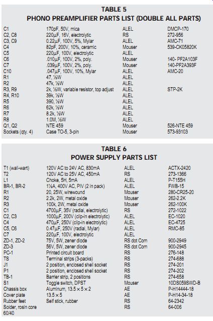
PHONO PREAMPLIFIER PARTS LIST (DOUBLE ALL PARTS)
C1 170pF, 50V, mica ALEL DMCP-170 C2, C8 220µF, 16V, electrolytic RS 272-956 C3, C9 0.22µF, 100V, 5%, Mylar ALEL AMC-71 C4 82pF, 200V, 10%, ceramic Mouser 539-CK05820K C5 220µF, 100V, electrolytic ALEL C6 .010µF, 100V, 2%, poly. Mouser 140- PF2A103F C7 .039µF, 100V, 2%, poly. Mouser 140-PF2A393F C10 .047µF, 100V, 10%, Mylar ALEL AMC-20 R1 47, ½W ALEL R2 47k, ½W ALEL R3, R9 2k, ½W, variable resistor, top adjust ALEL STP-2K R4, R10 39k, ½W ALEL R5 390, ½W ALEL R6 62k, ½W ALEL R7 8.2k, ½W ALEL R8 1.0M, ½W ALEL Q1, Q2 NTE 459 Mouser 526-NTE 459 Sockets (qty. 4) Case TO-5, 3-pin Mouser 573-93103
--------------------
TABLE 6
POWER SUPPLY PARTS LIST
T1 (wall-wart) 120V AC to 24V AC, 830mA ALEL ACTX-2420 T2 120V AC to 25V AC, 450mA RS 273-1366 L1 Choke, 5H, 5mA ALEL P-T155H BR-1, BR-2 1½A, 400V AC, PIV (2 in pack) ALEL FWB-15 R1 20, 25W, wirewound Mouser 280-CR25-20 R2 2.2k, 2W, metal oxide Mouser 262-2.2K R3 100k, 2W, metal oxide Mouser 262-100K C1 4700µF, 35V (radial, electrolytic) RS 272-1022 C2, C3 1000µF, 200V (clip-in electrolytic) ALEL EC-1020 C4 470µF, 250V (clip-in electrolytic) ALEL EC-4725 C5, C6 0.47µF, 250V (radial, Mylar) ALEL RMC-85 C7 220µF, 100V, electrolytic ALEL ZD-1, ZD-2 75V, 5W, zener diode RS dot Com 900-2949 ZD-3 56V, 5W, zener diode RS dot Com 900-2945 PC-1 Printed circuit board RS 276-148 TS Terminal strips (3-packs) RS 274-688 J1 2 position, enclosed shell socket RS 274-201 P1 2 position, enclosed shell socket RS 274-202 TB-1 Barrier strip, 2 positions RS 274-658 S1 Toggle switch, DPST Mouser 10DS059SWD-B Chassis box Aluminum, 13.5 × 5 × 2 AE P-H14444-18 Cover plate 13.5 × 5 AE P-H14-34-18 Rubber feet Self stick, rubber RS 64-2342 Solder, rosin core RS 64-006 60/40
---------------------
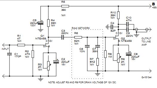
FIGURE 4: The phono amplifier schematic. NOTE: ADJUST R3 AND R9 FOR DRAIN VOLTAGE OF 12V DC.
It is obvious that calculations or SPICE is incapable of determining what the proper bias is for individual FETs. The obvious solution was a vari able resistor installed in the source circuit for each of the four FETs. Adjusting the FETs to obtain 12V DC pro vides a high degree of assurance that these devices are operating at mini mum distortion. The electrical characteristics information of the four FETs used in the phono amplifier are shown in Table 3. Note that the only variable of any significance is the source bias voltage.
Note: You can add a 1000µH, 14 ohm, R-F choke (Mouser, 542-77F102) to the input of the phono amplifier, if needed, for R-F suppression. I did not have any problem in this area with R-F interference. The choke goes between the phono jack and 47 ohm resistor.
The +56V DC/5mA power to operate the FETs is obtained at the junction of zener diodes ZD-2 and ZD-3 of the power supply (Fig. 3). The regulated +56V DC power "feeding" the phono amplifier has a significant impact on the sound of the control unit.
Important: I recommend that if you build FET circuits you have an audio oscillator and vacuum tube voltmeter or DMM, but you can still achieve good results with only a DMM.
The FETs provide a very detailed and clean output with a solid bass response. The high-and mid-frequency bands are reproduced with exceptional clarity. FETs also have linear phase characteristics over their bandwidth for maximum signal integrity, low distortion, and high dynamics with output signals not exceeding 2V RMS. Refer to schematic diagram (Fig. 4) of the phono amplifier for further technical information.
The cost of the phono amplifier is $34 and includes four NTE459s. It is recommended that you order an additional four NTE459s, which cost $2.66 a piece. (Important: The ECG 459 is not compatible with the NTE459, so do not attempt a substitution.) The 2V RMS limited output capability of a FET is the reason FETs are not suitable for a line amplifier. However, vacuum tubes are well suited for this application, and the 5687/12B4A with its low distortion and high output voltage makes it especially appropriate. I am very impressed with the performance of the 12B4A.
CONSTRUCTION
The locations of major parts are self evident from Photos 1 and 2. The coupling capacitors with a black band face to ward the negative side of the circuit. All the electrolytic capacitors are grounded at the negative band, except those connected in series. The high voltage electrolytic capacitors (C2, C3, C4) in the power supply section of the control unit (Fig. 3) are mounted on the PC board (RS-276-148). In the phono amplifier section (Fig. 4), seven 5-pin terminal strips are required. Components mounted on these terminal strips are as follows (numbers indicate location order of terminal strips. Components that have one end tied to a terminal strip are not mentioned).
1. R2 (R+L), R4 (R+L), C5 (R+L)
2. R3 (R+L), C2 (R+L)
3. C6 (R), C7 (R), R7 (R)
4. C6 (L), C7 (L), R7 (L)
5. R8 (R+L)
6. R9 (R+L), C8 (R+L), C11 (R+L)
7. B+ tie points, R11 (R+L), R5 (R+L)
Note: R-Right channel, L-Left channel It is very important that you tailor the assembly around the implementation of the eleven 5-pin terminal strips.
Using the terminal strips provides a very simple step-by-step construction process. It also permits easy change ability of parts.
--------------
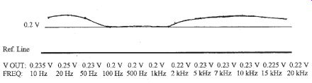
FIGURE 5: Phono preamplifier RIAA frequency response curve. Note: 0.1V RMS to input of inverse RIAA network at all frequencies and output of network connected to input of phono preamplifier. Adjust line amplifier output for 0.20V at 500Hz.
---------------
Building the control unit is a fun, easy project using the 5-pin terminal strips and a "nightmare" using a PC board. Also, use point-to-point wiring and do not use a common ground. To assure simple and effective grounding of all components, use an aluminum chassis box.
It is important all audio that runs approximately 3’ or more use standard shielded microphone cable and that the shield is grounded at both ends. It will only be necessary to ground the shielded leads at the output of the phono amplifier at the end nearest the output of the amplifier. The 5-conductor shielded cable that connects to the 6-position rotary switch must be grounded at both ends. Most grounds are made to the center post, 5-pin terminal strip. I also recommend that you use chassis-mounted solder ground lugs. Add a ground post near the input of the control unit for the ground wire of the record player motor. A bottom cover plate of the chassis is required to reduce noise pick-ups.
----------
TEST EQUIPMENT USED
H-P distortion analyzer, 331A Heathkit sine-wave, square-wave, audio generator, IG-5218 DMM, Radio Shack 22-168A Oscilloscope, Proteck, Model 6502
PARTS SUPPLIER
RS = Radio Shack RS dot Com = 800-442-7221
AES = Antique Electronic Supply 480-820-5411
ALEL = All Electronics 800-826-5432
Mouser = 800-346-6873
WARNING---Lethal voltages are present. Exercise extreme caution when constructing and testing the control unit and never leave it upside down when children are present.
--------
In conclusion, this is a control unit with several unique features, the most important is its exceptional "concert hall" life-like sound. This hybrid control unit is one of the best devices I have ever built and provides many hours of listening pleasure. I hope the information on the use of FETs was helpful.
-------
Also see:
A 6AS7/6080 CIRCLOTRON AMP---Check out this affordable, relatively easy to assemble project that's a good introduction to circlotron amp design.