BUILD A PLASMA TWEETER---Here's a hot idea--ion tweeters you can build to reproduce high frequency sound that's clean, clear, and totally non-directional.
-------
Generate audio from a massless electric flame to produce perfect transient response and an omnidirectional frequency response.
By Colin Joye
All dynamic cone, electrostatic, and ribbon tweeters have a small mass associated with their respective sound producing elements. A tremendous amount of work has been done to minimize this moving mass because it is often the limiting factor of how well the tweeter will perform. Another drawback to loudspeakers that use moving elements to produce sound is directionality.
Any element that moves to cause sound does so by pushing the airwaves in a specific direction. Some tweeters combat this by using a horn, others by using multiple drivers. In the case of the former, the frequency response is not perfectly uniform over the angle of dispersion, while in the latter, a lobing effect is often unavoidable. Having a uniform frequency response for off-axis angles prevents the listener from being confined to a single "sweet spot," where all of the axes of all of the speakers converge.
Of course, if your ears are not equidistant from any pair of sound sources, you will experience a phase shift associated with the different path lengths, but you still want the same frequency response, even off-axis. This project doesn't constrain you to experience only one fixed soundstage, but al lows the soundstage to rotate before your ears as you walk around the speakers, adding to the illusion of "being there."
ION TWEETER SOLUTION
You can use the laws of diffraction to make the width of the dispersion field wider by decreasing the surface area of the moving element with respect to the wavelength of sound being emitted (Fig. 1). The problem is that, by reducing the surface area, the sound output level is also reduced and the frequency response becomes restricted, so this would be a rather impractical solution to the problem. One clever way to conquer both directionality and moving mass is to use an electric flame.
Dr. Siegfried Klein invented the ion tweeter (or plasma tweeter, as it is also known) in the early 1950s. He used a push-pull vacuum tube oscillator to drive a coil at its self-resonant frequency to cause voltages on the order of 30,000V (30kV), which he used to produce corona discharge.
One problem that was prevalent in power transmission lines in the 1920s and 1930s was the formation of corona discharge on power lines. When high voltages are present at sharp points or edges, a bluish glow discharge known as corona discharge forms around the sharp point. Corona discharge is a localized ionization of the air that con ducts electricity. Any such gas that con ducts electricity is known as plasma.
In power transmission lines, this corona caused the insulation to disintegrate, because corona is a hot glow discharge. Dr. Klein's invention made use of this corona to produce audible sound.
He touted it as being able to produce sound with tremendous efficiency (he was ignoring the oscillator itself, which actually draws a lot of power) and as being able to project sound very audibly over large distances (as described in U.S. patent number 2,768,246).
In the late 1950s and 1960s, ion tweeters were produced commercially in the USA and Europe under the names Ionovac, Ionofane, and Ionophone (I recently spotted one for sale on eBay.com). These units used a metal horn to focus the sound and facilitate mounting. They used a single 6DQ8 tube to produce the corona and used tubes in the amplification stages.
Since then, there have been few ion tweeters produced commercially. The German company Magnat produced a three-way speaker cabinet in the 1980s and used an ion tweeter without the horn to make use of the omni-direction al effect. Acapella, another German company, currently produces very expensive and very high quality speakers that use ion tweeters.
This project presents the ion tweeter that I have constructed (Photo 1) and illustrates its theory of operation, construction techniques, feasibility, and some of the observations I've been able to make. I actually got the idea for my first ion tweeter on the web from Ulrich Haumann's webpage, now plasmatweeter.de. After I read how it worked and what it did, I just had to build it.
---ABOUT THE AUTHOR: Colin Joye is a 2002 graduate of Villanova University in Electrical Engineering. He is currently pursuing his PhD in electromagnetics at Massachusetts Institute of Technology. His other interests include music composition, art, and karate.---
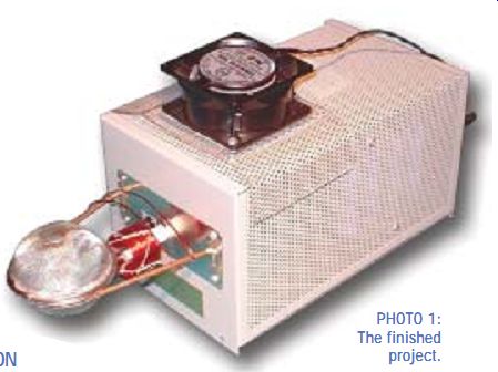
PHOTO 1: The finished project.
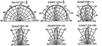
FIGURE 1: Normalized directionality characteristics of a circular piston
source as a function of diameter and wavelength (Ref: Olson, Harry F.,
Music, Physics and Engineering. New York, 1967, 2nd edition, p. 103).
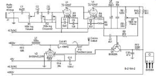
FIGURE 2: The Plasmatone-RG1 preamp and oscillator schematic. The preamp
section is the upper half of the schematic, while the oscillator section
is the lower half.
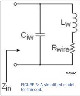
FIGURE 3: A simplified model for the coil.
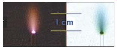
PHOTO 2: The corona discharge on the electrode (left); shown with inverted
colors (right).
The ion tweeter schematics I used for this project are similar to the first pair I built, with a few modifications, such as the 12AX7 tube preamp stage. The first pair has a lot of problems, so I built a better, more reliable second pair, as presented here. I am presenting the schematics exactly as I have used them, but there are many things I think can be enhanced in the schematics, so I have included a section of recommendations that you should read before at tempting to build this project.
ABOUT THE FLAME
The corona flame is very peculiar be cause it stands by itself on top of a single electrode, not between two electrodes, like a Jacob's ladder or spark gap transmitter. This feat is quite mind boggling to the typical experimenter who is used to seeing sparks appear be tween two points. In fact, even the resonant coil that is the heart of the project is only connected at one end! The ion flame looks a lot like a candle flame (Photo 2), although it is slightly bluish or white in color. Furthermore, the flame acts like a perfect point source, which means that the acoustical energy is emitted spherically with a perfect uniformity in frequency response.
I like the ion flame be cause it operates on the same principle that nature uses to produce sound by lightning and thunder. Unfortunately, the low-frequency extension of the flame is limited by its size.
You probably could have guessed that, since thunder can easily reach down to 1Hz or less, requiring millions of watts of electricity in the process, while the spark you get stepping out of your car on a winter day gives you just a little more than a high-pitched snap.
For a 1cm flame height (around the same size and shape as a medium candle flame), the frequency response hits -3dB around 2kHz. The upper limit of the frequency response is well above the hearing threshold. It has been measured up to 40kHz, but my guess is that it may extend up into the megahertz. If you were to send bass frequencies to the flame, it would be like sending bass frequencies to a tweeter. It will try to re produce the frequencies, but it won't do it very well! This project draws around 200W of wall power to produce that 1cm flame, so if you were thinking of making an ion subwoofer next, forget it! You would need a lot of power. Subwoofers tend to be non-directional in small rooms any way, so only the higher frequencies re ally need to be addressed.
Those of you familiar with spark generation know that where there are sparks, there is the pungent smell of ozone. The corona flame, however, is not a spark, so there is almost no ozone. Since the flame is hot, the ozone that it does produce rises straight above the flame, but there really isn't enough of a smell to cause an annoyance or health hazard. Besides, ozone kills bacteria in the air! The corona flame does generate a lot of heat, and it is a high-voltage hazard, so be very careful when you are working around it. Furthermore, it acts like a little source of a lot of radio frequency interference (RFI). The Federal Communications Commission (FCC) has a lot to say about such things, so I bought a steel mesh food strainer to put around the flame (Photo 3). This grounded shield allows the air-waves to pass through, but prevents electromagnetic waves from propagating. You can see how it works if you pass a small fluorescent tube by the flame without the shield--it will light up 6” from the flame! Incidentally, since the oscillator frequency is very high (around 30MHz), you won't get a shock from the flame, but a radio frequency (RF) burn. Since the flame is so hot, you need to use a copper electrode to sink the heat.
I tried a piece of stainless-steel wire once, but it melted! The copper still is slowly "eaten" away by the flame, but there aren't many other options for the electrode material. In the 1960s, they used thoriated tungsten quartz-glass electrodes that retained their sharp ness for up to 1200 hours.
CIRCUIT OPERATION
Figure 2 shows the schematic I used for the preamp, amp, and oscillator portion of the project. I like to start with the oscillator, because explaining it first helps explain other parts of the system.
The heart of the oscillator is what I call the "Tesla" coil. It is not the Tesla coil some of you may be familiar with because it doesn't have a primary and secondary, but it does operate at the self-resonant frequency of the coil. This coil acts similar to a parallel resonant circuit (Fig. 3), where the windings are the inductance component and the interwinding capacitance leads to the capacitive component. The key to producing the high voltages is to have a very high Q-factor for this resonant circuit.
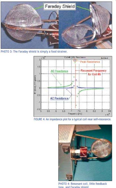
PHOTO 3: The Faraday shield is simply a food strainer.
PHOTO 4: Resonant coil, little feedback loop, and Faraday shield.
FIGURE 4: An impedance plot for a typical coil near self-resonance.
By definition, Q = (2p f0)/bandwidth = (2p f0 L)/R where f0 is the resonant frequency in hertz, L is the inductance in henries, and R is the resistance in ohms.
So to get a high Q, the resistive losses need to be small and the inductance large. Since the coil acts like a parallel resonant circuit and the losses will be small, then at the self-resonant frequency of the coil, the coil looks like a near open circuit (Fig. 4). From Ohm's law, if a current is put across a very large resistance, the result is a very high voltage. In his 1956 U.S. patent number 2,768,246, Dr. Klein noted that an audible hiss was present if the oscillator operated at frequencies below around 3MHz, which sets the mini mum acceptable self resonant frequency.
Actually, I found that the resonant frequency should be kept above 10MHz to avoid flickering of the flame.
The 6KG6A pentode I used for the oscillator has a gain-bandwidth limit of around 70MHz for this design, so I wanted a self-resonant frequency of around 40MHz for the operation. The reason I chose it so high was that a lower resonant frequency would require more inductance, which means more wire and more losses.
In order to design the coil to oscillate at a certain frequency for a parallel resonant circuit with negligible losses, you can use the following simple equation:
f0 = [2pv(CiwLw)] -1
where Ciw is the interwinding capacitance and Lw is the winding inductance. Unfortunately, there is no practical way to accurately estimate Ciw, so I wound several coils until finding a suit able one.
By the way, you cannot simply make the inductance extra small to lower losses and then put a high-voltage capacitor in parallel with it to lower the resonant frequency, because the Q equation would predict a small Q. Also, you can't use Litz-style wire (a bundle of small-gauge wires to lower loss) be cause corona favors sharp edges! The only options left are heavy-gauge cop per magnet wire or superconductors! I chose 16ga copper magnet wire be cause it seemed to do the job well with out too much loss or being too bulky.
My coil is wound with a diameter of 1 3/8” (35mm) with 15 turns. Since I didn't have a ceramic, glass, or other wise suitable core to wind the coil on, I wound it on a cardboard tube and then threaded the turns together so they wouldn't move when I took the coil off the cardboard. Each turn is then separated by the width of a piece of thread.
The resonant frequency of these coils is around 40MHz, as desired. I don't think there would be any problems if the resonant frequency was as low as 10MHz or as high as 50MHz. I dared not wind the coil on anything that would melt at high temperatures after I found that the coils became quite hot on the first ion tweeter pair. I originally thought this heating was due to the resistive losses, but now I think it was simply heat conducted away from the hot corona like a heatsink. I think it would even be okay to wind the coil on PVC piping, provided there is no direct path for the heat generated by the corona to use your coil as a heatsink.
Place a simple feedback loop around the output electrode in order to tell the oscillator tube when to turn on and off.
This feedback loop is nothing more than an insulated wire placed on the output-side of the resonant coil. It does not touch the output electrode, but hovers near it, no closer than about ¼” (6mm). My feedback loop is around 1” in diameter and is securely fastened to prevent it from moving too near the electrode. See Photo 4 for the coil and feedback loop assembly.
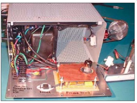
PHOTO 5: The disassembled ion tweeter.
INDUCTOR SELECTION
The 100µH inductor is simply an RF choke that lets DC pass through to the tube, but blocks AC from coming back to the power supply. I tried several different inductors and found that some kinds actually didn't work very well due to lossy ferrites with low Qs. The best choke was the Xicon 1A, 100µH inductor that was wound using only one layer (which prevents inter-layer coupling). Curiously, when I put it on the impedance analyzer, its self-resonant frequency of around 3.2MHz was well below the operating frequency of the circuit (around 40MHz), which means it should be acting more like a capacitor at that point than an inductor, although probe capacitance may have thrown the resonant frequency measurement off.
Nonetheless, it works, but I'm wondering whether this could be causing interference in my 120V power lines.
By the way, I did experience interference problems with my portable CD player. Since portable CD players are not normally shielded, they easily pick up interference from the air or power lines. My first ion tweeter prevented my portable CD player from functioning properly whenever the flame was on!
TUBE OPERATION
When you first turn on the power, the sudden disturbance causes the self resonant coil to begin to oscillate. The feedback wire senses this and triggers the tube to shunt the power rail toward ground. When that happens, the current in the coil shifts and causes further disturbance. At this point, the circuit is oscillating, but no corona is present.
In order to initiate the corona, you must momentarily touch an isolated screwdriver to the tip of the electrode.
The proximity of such a conductive body causes the voltage gradient (e.g., kilovolts per centimeter) to increase above the critical threshold of visual corona (Peek, F.W., Dielectric Phenomena in High Voltage Engineering, Third Edition, McGraw-Hill Book Company, Inc., 1929, pp. 54-59). The corona is self-sustaining once this critical threshold has been reached.
After constructing a solid-state version of this ion tweeter as a senior project, my team and I are just beginning to understand how to produce a self-starting corona. If the power to the oscillator is switched on quick enough, a burst of high-frequency energy con tent is produced at a substantial level.
The high Q of the coil causes it to select the frequency it wants to see and reject all others. If this initial burst is at a high enough amplitude, the corona will self-start; otherwise, it will need to be started mechanically. My senior project team has been able to self-start the corona discharge reliably using this approach with solid-state devices. The 6KG6A pentode, like all pentodes, has three grids. Grid #1 is the oscillator grid because it is the most sensitive and has very low shunt capacitance. The low shunt capacitance is important because the feedback loop is nothing more than a wire placed near the electrode to sense the output by capacitive means. The shunt resistor be tween Grid #1 and ground acts as a self bias to ensure that the tube sustains class C operation.
Grid #2 requires a DC bias to set the current flow in the tube, and thus the height of the flame. By adding an AC signal to this DC bias, the flame height can be changed very rapidly. The flame system works like a Class A circuit: the steady-state size of the flame is set by the flame control potentiometer, and the AC signal causes the flame to shrink down to a minimum size and expand up to a maximum size. If the AC component causes the corona to extinguish momentarily, the signal will be audibly clipped. Likewise, if the peak AC signal causes the tube to saturate, clipping will result.
If the steady-state flame height is set too high, the plate of the 6KG6A will quickly begin to glow orange, a sign that the tube is being operated outside of its safe area. The 6KG6A, like most power tubes, generates a tremendous amount of heat under normal operation.
WHY IT WORKS
One possible explanation for how the corona generates sound is that the flame is hot, so the air density is lower than that of the surrounding air. This causes an air density gradient boundary that moves with the flame height, producing sound waves.
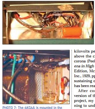
PHOTO 6: The simple oscillator circuitry is mounted under the 6KG6A socket.
PHOTO 7: The 6KG6A is mounted in the front of the enclosure.
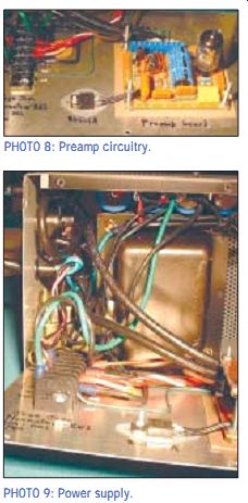
PHOTO 8: Preamp circuitry.
PHOTO 9: Power supply.
Another explanation (as used by Dr. Klein) is that the bulk of the collisions between positive air ions and air molecules causes spherical piston-like variations in the air column, producing elastic pressure waves. There is no known upper limit to how high the sound pressure level could be made if the plasma flame was large enough. I have measured sound pressure levels of 108dB at 3” from the flame, but I'm sure it could become louder if the conditions were right.
Putting the audio and DC bias into the Grid #2 of the tube requires around 10mA at 20V to 100V (roughly).
The maximum peak-to-peak voltage of the AC component should be around 50V. A simple BU508A NPN power transistor in common-collector configuration provides the necessary current gain to accomplish this interfacing of the preamp and oscillator tube. The BU508A is a horizontal sweep-type power transistor used in television, so it can handle a considerable amount of voltage and current. It really does not need a heatsink, but I mounted it on the aluminum cover just to be sure that it didn't overheat.
The DC bias level is set by the 100 k-O potentiometer (marked "Flame" in Fig. 2), while the 12AX7 tube pro vides the AC voltage. I found it was necessary to use the cathode-follower configuration for half of the 12AX7 be cause of the current needed to drive the BU508A power transistor. Because of this common cathode-to-cathode follower configuration, the overall gain is a bit lower than just one section of the 12AX7.
I didn't put any other gain stages in for some reason, but it really does need about 30dB more gain. To get full volume output with my schematic, you need about 6V of peak-to-peak audio on the input.
Keep in mind that I am not much of a tube expert. I did no load line analysis for this preamp stage, and I'm not even sure whether you can use the term "small signal approximation" for a 12AX7 pushing 50V AC without nonlinearity problems.
The input of the preamp section filters the audio input by the simple variable high-pass filter, which has a vari able cutoff point of around 500Hz and up. As mentioned earlier, it is important to have some kind of high-pass filtering somewhere along the road.
The power supply for the ion tweeters is shown in Fig. 5. I don't like it at all, because I used a voltage doubler circuit to obtain the necessary 600V DC.
Such a circuit has increased 60Hz noise present and bad power-supply ripple. I suggest using a center-tapped (CT) transformer rated somewhere around 800V with a full-wave rectifier and choke-input instead.
I had problems with my power switches blowing out on the 600V/300V supply because of the large current spikes when turning the sys tem on and off, so this is part of my motivation for recommending a choke before the capacitors. Also, I used a little 1.2A 12VCT transformer for the 6KG6A filament, which is rated at 2A, so you should obviously change that.
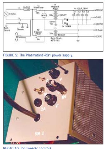
PHOTO 10: Ion tweeter controls.
FIGURE 5: The Plasmatone-RG1 power supply.
PERFORMANCE
Since I spent most of my time getting the concept to work, I really didn't do much in the way of tweaking it for perfect performance. I think there are some relatively severe nonlinearity problems somewhere in my design, but it's because I'm really only using it above 3kHz; it is not readily apparent to the untrained ear. I'm sure that proper designing and tweaking will ad dress most of the nonlinearity, because I believe that the corona discharge is an excellent substitute for any kind of moving-element tweeter.
Everyone I've demonstrated it to thought the concept and sound quality were absolutely incredible. I really like the omnidirectional aspect of the tweeter, as well as the concept of mass less sound generation. It is absolutely amazing to walk around the stereo sys tem and have the high frequencies be perfectly uniform at all directions. It is perhaps even more impressive when the lights are turned off and you are greeted by the dancing white-purple electric flame and warm glow of vacuum tubes. CONSTRUCTION AND TROUBLESHOOTING
I set out to build an integrated, sturdy ion tweeter when I began this project.
To accomplish those goals, I put every thing into a Hammond perforated-steel cage and simply drilled holes in the edge for the bottom plate.
In retrospect, I don't think it's a good idea to mount the power supply in the same case with the electronics, because I had a hard time getting rid of some extra noise. I also think they could look a lot more elegant if the tubes were showing and had some kind of Frank Lloyd Wright theme with tall skinny capacitors and tubes. I pretty much stuffed everything into the steel enclosure and then had no room for the fan I decided to add later to cool the 6KG6A tube.
Photo 5 shows the tweeter in its disassembled state. The 6KG6A tube and oscillator circuit (Photos 6 and 7) fit inside the front of the enclosure, while the preamp board is mounted on the bottom cover plate (Photo 8). The pre amp board shown in Photo 8 actually has some extra circuitry on it that is ...
------------------------
PARTS LIST
ION TWEETER PARTS USED, VACUUM TUBE VERSION AUDIO PREAMP REF ITEM
C1 0.22µF, 250V capacitor C2, C3 1.2nF, 100V capacitor C4, C6 0.1µF, 63V disc capacitor C5 1.5µF, 50V capacitor C7 4.7nF, 100V capacitor C8 47µF, 350V capacitor C9 10nF, 400V capacitor C10 47nF, 400V capacitor J1 RCA jack Q1 BU508A horiz power transistor R1 100 k-O potentiometer, log R2 250 k-O dual potentiometer, log R3, R4 1.4 k-O, ¼W resistor R5 1M ohm , ¼W resistor R6 120 k-O, ½W resistor R7 100 k-O potentiometer, lin R8 33 k-O, ½W resistor R9 47 k-O, ½W resistor R10, R11 3.3 k-O, ½W resistor R12 22 0 ohm, ½W resistor V1 12AX7 preamp tube PCB 4”× 6 "
12AX7 tube socket RS #276-1388, PCB blue wire terminals (5)
HIGH VOLTAGE OSCILLATOR REF ITEM
Coil #1 16ga magnet wire (~6ft)
C11 1nF, 1.6kV disc capacitor L1 Xicon 100µH, 1A RF choke R13 18 ?, 10W resistor R14 39 k-O, 1W resistor V2 EL519/6KG6A tube EL519 tube socket (Magnoval)
POWER SUPPLY
REF ITEM C1, C2, 100µF, 350V capacitor C3, C4 D1, D2 1N5404 rectifier diode MOV1 Metal-oxide varistor, 120V S1 Power switch 15A S2 Power switch 6A SLO 2A slow blow fuse T1 Magnetek #N66A, 230VCT, 250VA T2 Radio Shack #273-1352, 12.6VCT, 15VA Fan Fan for heat removal
OTHER
Tea Ball (Faraday Shield), 3 " diameter Case ( Hammond) Miscellaneous hardware
-------------------
WARNING!
This project utilizes potentially lethal voltages and should not be attempted by those unfamiliar with high voltages. The corona discharge is produced by volt ages in excess of 20,000V and poses a tremendous heat and fire hazard if exposed to combustible materials. Furthermore, the operation of the corona dis charge is such that it operates in the radio frequency range of 20MHz to 70MHz and is capable of causing radio frequency burns. This unit may emit severe radio frequency interference, so you should use the Faraday shield described in the text to block the RFI and protect the user from coming into contact with the corona discharge flame.
----------------------
... not currently being used. The power supply is tucked away in the back half of the Hammond case (Photo 9), and the controls are mounted in the rear (Photo 10). Even though the oscillator circuit is astoundingly simple, I suggest building it first on a nice big piece of wood so you can make sure it's working before squeezing it into some small space and integrating it with the audio stages.
This will save you a lot of in-circuit troubleshooting time. Beware of unexpected feedback or interference, since you are operating at high frequencies where anything can happen. Make sure you decouple the power supplies to pre vent the strong oscillations from causing more interference and annoying 60Hz hum.
CONCLUSIONS
This project was a very fun and interesting one for me. Not only does it demonstrate the feasibility of massless audio reproduction and omni-directionality, but also does it in an elegant, al most sci-fi way. I highly encourage the real audiophiles out there to try to bring this idea up to the highest sound quality standards most audiophiles hold. I didn't have the money for expensive audio capacitors, nor did I have the expertise necessary to tweak this project to perfection, but I hope someone out there will! Ultimately, the ion tweeter would operate not just at tweeter frequencies, but also at midrange and maybe even upper woofer frequencies. I would love to see a two-way stereo using a sub woofer and plasma speaker. In fact, I'm soon planning to build an ion speaker using the powerful 813 transmitter tube to try to accomplish this goal.
My senior project involved using a field effect transistor as an on/off switch in place of the lossy vacuum tube to increase the power efficiency of the oscillator section. Increasing the power efficiency was the first step in increasing the size of the flame, since it's better not to throw away massive amounts of heat. In theory, it shouldn't matter what kind of device is being used to generate the corona, because the audio character is set by the pre amp stages.
RECOMMENDATIONS
• Redesign preamp stage for better linearity, dynamic range, and higher gain for compatibility with RCA-level signals.
• Use power supply with less DC ripple.
• Build a ramp-up circuit for the power supply to prevent large inrush current when turning on the supply.
• Try a better RF choke for less power line interference.
• Try to build an auto-start for the corona by injecting an impulse of current through the tube.
• Try multiple tubes in parallel for a larger flame and wider frequency response.
-------
Also see:
A HYBRID STEREO $90 CONTROL---With its low cost and simple circuit architecture, this high-quality control unit is one you can easily add to your audio system.