Once again, synchronous rectification solves a pesky
problem caused by diodes.
By MK
A couple of years ago I built an isolation transformer with a variable autotransformer, or Variac ohm, so that I could work safely on hot-chassis equipment. I also use it on my regular projects because the Variac allows me to power them up slowly so I can check voltages and find shorts before something blows up. I hate being surprised by a puff of smoke or a burned finger.
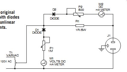
FIGURE 1: The original meter circuit with diodes that produced un-linear
meter movements.
+++++++
ABOUT THE AUTHOR
MK just earned his BSEET from Roosevelt University and is a brand new 44-year-old engineer at Northrop Grumman, a major defense contractor. Prior to that, he was an electronic technician there for 20 years. Kornacker is still in school working on a Master's degree in computer science. He got started in electronics because of his dad, who was also an electrical engineer at the same company. Kornacker also has two beautiful daughters.
++++++++++++
HUGE TRANSFORMERS
The idea for this project came from Electronics Now magazine (Dec. 1997, p. 18), which suggested using two identical high-voltage transformers hooked up secondary-to-secondary. I found two huge surplus 380V 500VA transformers. At 120V they could supply 4A of current, which was perfect.
The Variac I used was a 3A model connected to the primary output of the second transformer. I also used two DC milli-ammeters to measure the Variac output voltage and the current flow of any device I plugged into it. All this I in stalled in a large aluminum box along with a small fan, an on-off switch, a fuse, an outlet socket, and other miscellaneous requirements.
The metering circuit (Fig. 1) gave me some problems. Since the meters were DC, I used diodes to half-wave rectify the voltages so they would work properly. The problem is that PN junction diodes such as these are non linear devices. The diode resistance is not constant, but varies with the amount of current passing through it.
If I doubled the voltage of the Variac or the load current, the meters would not show a corresponding linear increase. I could easily have re-marked the meter faces to reflect this, but I am an idealist.
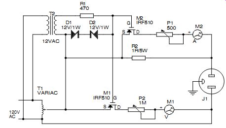
FIGURE 2: Using a synchronous rectifier circuit makes a perfect diode
and linear meter movements.
I then tried using Schottky diodes because they work on a different electrical principle than the PN junction types. These worked better in the circuit, but still were not good enough.
Germaniums that I tried were also un linear. What I desired was the perfect diode, a linear device that would let me accurately measure AC with a DC meter, no matter what the level.
One way to measure AC current only is to use a current transformer with the primary winding in series with the main line and the secondary winding connected to a diode rectifier and DC meter. This method works by converting the current to a proportional voltage and then stepping it up so the diode works in its linear region. A toroid transformer would be perfect for this, but would require me to wind my own, so I chose not to go that route. If you would like more information, see Eric Lowdon's work [1], which contains an excellent chapter on current trans formers, with all the details.
SYNCHRONOUS RECTIFIER
A simpler way to solve my dilemma of measuring AC voltage and current with DC meters is with a synchronous rectifier using a power MOSFET transistor and a 12V transformer (see my article, "Try Synchronous Rectification," AE 5/00, p. 26). It makes the perfect non-diode diode rectifier. One of the beau ties of a MOSFET is that it does not have a PN junction voltage drop like a bipolar junction transistor. Its voltage drop acts more like that across a standard resistor-an IR voltage drop. Actually, it is exactly like a resistor, albeit a silicon one, and resistors, we know, are for the most part linear devices. It is this characteristic that I wished to take advantage of.
Figure 2 shows the synchronous rectifier circuit in a half-wave configuration. The basic circuit uses a small 12.6V AC 300mA single secondary transformer and two IRF510 n-channel MOSFETs. The peak unloaded voltage of this auxiliary transformer was about 23V, information that is important because the MOSFET gate with respect to source bias, for saturation, must be greater than 10V peak but less than 20V peak to prevent transistor destruction.
In other words, when the source goes positive, the gate must go more positive by the aforementioned amount, but not any more than that. Since the gate voltage was over the allowable, I incorporated as a limiter two 12V, 1W zener diodes (1N4742A) connected in a cathode-to-cathode connection and a 470 ohm, ½ W dropping resistor.
The secondary of this transformer, you will notice, is connected to the wiper of the Variac. The phasing is such that the gates of the transistors are always switching at the line rate, regardless of where the wiper is set. If the wiper is just off 0V, for example, the transistors are ready to rectify the voltage for each of the meters.
DEDICATED TRANSISTORS
Each meter has its own transistor. I tried a single transistor for both, but for some reason I have not yet fathomed the current meter would pin the needle when the Variac was set to a certain point. Apparently there was an unexpected voltage-divider-path problem between the 1 ohm shunt resistor and the ½ ohm MOSFET on-resistance that fortunately was cured by using dedicated transistors for each meter.
The zener-diode circuit across the auxiliary transformer's secondary also helps protect the gates from power-line high-voltage spikes and transients that could destroy them. I also installed a 200V metal oxide varistor (MOV) across the primary of the transformer for some added safety. All the parts used, the 12V transformer, MOSFETs, zeners, resistor, and MOV can be found at your local parts store. Finally, no heatsinking is required for the transistors, since they do not draw any appreciable current.
Now my problem is solved. When I increase the Variac voltage or when the load draws more current, the meters read in a linear and predictable fashion. Using synchronous rectification in this manner solved an annoying measurement problem. It allowed me to use DC meters to measure AC without the bad side effects caused by the nonlinear nature of diodes.
REFERENCES
1. Lowdon, Eric, Practical Transformer Design Handbook, Tab Books, 2nd Edition, Blue Ridge Summit, Pa, 1989, ch. 13.
----------------------
Also see: