CORRECTIONS
Thank you for printing my “Cap Solution ” in the April '05 Xpress Mail (p. 46). But 60 seconds later my heart hit my gut. I mixed up some values that were for another notation! Correction of crossover capacitors: for my 1980 pair of speakers BES D 280 geo-static; tweeters only, Bohlender Graebener neo 8-PDR; crossover: 9.0µF, 200V, metallized film and foil polypropylene MIT multicap. Four, 0.01µF, two are 400V polystyrene MIT multicap. The other two are 600V Infini Signatures.
The inductors: solo copper foil air core 16GA 0.50mH. This cuts off at below 1900 cycles or so.
The bypass capacitors are well within the 1/100 value of the 9.0µF larger capacitors, thus avoiding “spectual overlap, ” so says Infini's white paper on bypassing caps.
William R. Harren; Ridgefield, Wash.
Undoubtedly someone already has caught the upside-down Q1 transistor (emitter and collector are reversed) on page 32 ( “A Simple Audio System ”) of the April '05 issue. But just in case . . .
Jim Wood Brea, Calif.
Aren van Waarde responds:
You are correct. The emitter and collector of transistor Q1 (2SA970) in the class A amp schematic (Fig. 1) were indeed reversed.
Please accept my sincere apologies for this slip of the drawing program. I hope this error has not caused inconvenience to potential builders. It is amazing that I did not spot this in the proofs. I must be getting old.
TUBE ARCING (CONT.)
After reading Jim Carlyle's exchange with Edwin Pettis in Xpress Mail (Oct. 2004), I would like to add to some of the remarks that were made. I do believe your claim when you saw “metal shards ” responding to a magnet.
Edwin Pettis said:
“First off, none of the parts inside a tube has been machined. They are all stamp-formed and welded. ” Although this is true for most tubes, the Western Electric 255B had anodes machined from graphite. Metal parts are stamped and cut from a continuous strip of raw material. The shearing operation can produce small metallic slivers-some loose, some attached. I have seen slivers long enough to cause a short between grid and plate.
Metal tube parts must be free from dirt, lint, stains, and visible films of oil and grease. To accomplish this, parts are put in a dip basket and vigorously agitated in an acetone bath (brushing may be necessary). The basket sits in the acetone for five minutes and then agitated again. This process is then repeated two more times in fresh acetone.
Ultrasonic cleaning is also used.
Besides welding, plate halves are secured by punching several rectangular holes in the wings of the plate and then clinching the protrusions on the back side.
Many tubes have carbonized plates.
The powdery carbon will rub off.
Pettis said: “The only source of any kind of powdery residue inside of a tube is either the getter or the cathode oxide. ” Getters are usually circular (can be rectangular) and are made of iron formed into the shape of a trough, which may hold up to 5 mg. of barium stabilized with aluminum. It is flashed at approximately 700° C for five to ten seconds.
The flash deposits barium metal on the glass envelope as a silvery film.
Overheating can burn the ring and spew metal particles. The flash is directed away and shielded from the mica surface, since barium alloy on the mica will produce leakage paths. The flash adheres to the glass and absorbs gas during the life of the tube. Air in a tube will cause the flash to oxidize, turn white, and cause particles to peel from the glass.
Micas are spray-coated with magnesium oxide to reduce electrical leakage on the mica surface. It is a very fine white powder in a binder. The sprayed coating can vary from thin and smooth to thicker and powdery. It is not uncommon for some specks of this non-conductive powder to appear on the inner wall of the bulb as “dust. ” Many tubes have micas with tips around the periphery to engage the bulb for a secure fit against the glass wall to prevent noise and microphonism. During insertion of the tube mount, a small piece of the mica tip may break off and remain inside.
Prior to assembly, clear micas are washed in acetone, dried, and then heat treated in dry halogen at 500° C for 15 minutes. After coating with magnesium oxide, the micas are heat-treated again for 30 minutes. It is possible for small amounts of the MgO powder to flake off.
Electrical connections to stems, heaters, grids, and plates are made by resistance spot-welding. Heat forms a weld nugget, but sometimes a spark will fly and deposit minute metallic balls or slag particles onto the mica, envelope, or stem and may become loose. Many tube manufacturers washed the completed mounts in D1 water using a cascade washer to wash away particles.
Bulbs are shipped in cardboard boxes and subject to oxidation and humidity called “weathering. ” It appears as a thin, hazy film, and is washed off in an industrial “dishwasher ” using Calgonite. The film may appear as microscopic spots on the wall of the bulb. Foreign particles in the raw bulbs are washed away. Other methods of glass cleaning may use boiling water, deionized water, hydrogen peroxide, sodium hydroxide, diluted nitric, or hydrofluoric acid.
Due to mount assembly, stray barium carbonate particles from the cathode may end up on areas of the cathode where they don't belong. They will emit and, if outside of the grid-controlled area, can cause the failure of a “high plate current cutoff test. ” Cathode coating can peel from the cathode sleeve- usually caused by problems of cleaning, etching, or spraying of the sleeve.
It is true that most arcing is caused by a reduced space charge around the cathode. Some tubes have an arc test.
For example, the WE 422A, a large diode tube, has an arc test performed as follows: Heater voltage is reduced from a normal 5.7 to 5.1V, slightly lowering the space charge. Plate voltage is increased from 500 to 550V and then pulsed three times-no arcs allowed.
An arc may be slight or catastrophic. A tube with a slight arc was rejected but then re-aged and retested. A catastrophic arc could punch a hole and burn the coating, resulting in loose coating, short, low gm, low Ib, or gas.
Tube killers are mainly arcing, sulfur, chlorine, oil, gas, flicker shorts, dead shorts, burned or open welds, over voltages, heat, glass cracks, stem leakers, and leakage.
With good workmanship, cleaning, chemical processes, and good quality control, all of the occurrences I've mentioned are very minimal. But remember, Murphy's law applies to tube manufacturing and still says that, “Anything that can happen-will. ” Over the years, much effort was expended by Western Electric and the BTL to extend tube life. WE quality was always tops.
Bernard Magers
[Bernard Magers, former senior engineer for Western Electric, is the author of 75 Years of Western Electric Tube Manufacturing (available from Old Colony Sound Lab). -Eds.]
Jim Carlyle responds:
Thank you for the erudite exposition on tube manufacture, testing, and failure. And it's good to hear someone else testify to seeing “metallic slivers long enough to cause a short, ” in spite of all the apparently exhaustive manufacturing cleaning procedures.
In the November issue Edwin Pettis presented an even longer theoretical argument as to why the earth is not round, astronauts can't have reached the moon, and tube arcing can't be due to metal shards. I can only conclude that he still refuses to actually look for them himself using a neodymium magnet and 4-dioptre close-up spectacles, and prefers to look foolish. Over several de cades I often used to tell physics students who were skeptical about an experiment,
“The fact that 600 million Chinese have never seen this happen does not prove that it can't work. Try it now for yourself! ” Finally, may I add that, in spite of subsequently installing low-efficiency low-impedance Magnepan speakers last March, and regularly abusing the volume, I have had no more arcs since my tip and tap installation precaution as described in my first letter.
This is in spite of the replacement NOS GE USA 6DZ7 tube set now looking more discolored than the four-year-old previous set, because of higher than ever currents into my new 4 ” speakers.
My 46 years experience with tubes, including building amps for bands, does not support the Pettis story that hard-driven tubes gradually become more likely to arc due to falling emission. I now believe that so-called random tube failure is, in at least some cases, caused by the metal dust slowly migrating to the highest fluctuating field region, in my case between the plate and suppressor supports on the lower mica disc.
I saw the arc happen there, and found the shards (not globules), and similar shards in the other tubes which had not arced, and also in my stock of unused tubes. Abuse was only the secondary cause.
Now that I've tipped and tapped them all I feel safe. Just do it. It's free insurance. Who would argue against that?
TUBE QUALITY
I was interested in Ed Dell's follow-up to Eric Barbour's letter on “Cathode Stripping ” (Feb. issue) and would like to add to the dialog among Messrs. Pettis, Barbour, and Dell. I didn't get to read Ed Dell's article “The Brute ” in Stereophile, 1966, but saw the reference in the Feb. '05 audioXpress.
As a product engineer at Western Electric, I was responsible for, among others, the 422A, a large rectifier diode susceptible to arcing. The positive pulling force from the B+ voltage demanded electrons, and if they were few and far between, they would be “yanked, ” you might say, from the cathode surface to satisfy this force and could result in an arc.
Similar to Ed Dell's findings, arcing in the 422A could almost be eliminated by delaying the turn-on of the anode voltage by 10 to 15 seconds to allow the cathode to reach operating tempera ture. Because building a delay into the existing equipment in the field was a major undertaking, the BTL imposed an arc test to ensure that any failures would remain in the factory. The majority of tubes passed this test.
A distinction between “arcing ” and “sparking ” was made. An arc was dam aging enough to destroy the tube. A spark was at a level low enough, most of the time, not to be detrimental.
The arc test consisted of reducing the emission by lowering the heater voltage from a normal 5.7 to 5.1V. Anode voltage was increased from 500 to 550 and was pulsed on-and-off instantaneously three times. Failure was determined visually and by a sudden deflection in the anode ammeter. If a tube was prone to arcing, it usually occurred on the first pulse. It could be catastrophic, punching a hole in the cathode, resulting in loose coating, a heater-cathode short, low Ib or gm, or gas.
The oxide coating deposited by spraying was not always uniform. It consisted of a loose conglomeration of particles of an irregular shape with interspaces of different sizes. In later years, the particles could be precipitated to form them in the shape of either “rods” or “spheres.” A coating with an abundance of rods proved to be better for emission.
Under magnification, the coating surface was very rough with peaks and valleys. Also, emission from the coating was not always emitted uniformly; it varied from different areas of the coating and was dependent on the work function between respective areas. If the current drawn was increased, emission from these areas would rise and the difference between high- and low-emitting areas would become more pronounced.
If this continued, the temperature of the high-emitting areas would increase so much that coating evaporation would take place with an appreciable amount of gas. (High heat will sinter the coating and turn it into a hard non-emitting glaze.) The ions produced by this process tended to annul the negative space charge in front of the cathode and be come positive. Then particles of coating would be removed by evaporation, ion sputtering, and by electrostatic forces.
When operated at low temperature, the cathode emits a current which is nearly saturated and encourages a high positive field strength to form in front of the cathode. It follows that the sparking phenomenon more likely happens if the anode and heater voltages are switched on together, thereby eliminating the advantage of warm-up time.
Even with the cathode activated to optimum, sparking can still occur under pulsed operation before saturation cur rent is reached.
The mechanical strength of the coating is low, and consequently a high electrostatic force may tear particles from the surface, be attracted to the anode, and hit with a high velocity. This action produces a reverse current from the anode, particularly in rectifiers, causing intense local heating of the coating. A high emission current accumulates in a specific area, and, if high enough, will form a destructive arc to the cathode coating.
Destructive arcing is caused by drawing maximum emission before the cathode has reached normal operating temperature. Anode current is drawn from a reservoir (space charge) of electrons around the cathode. This reservoir is supposed to stay ahead of the anode cur- rent demand and, as long as it does, new electrons replenish those drawn away.
When a cathode is warming up from a cold start, its ability to supply electrons is fairly limited and is referred to as temperature-limited emission. If heavy demands are made, the reservoir will be completely drained away, leaving the cathode exposed to heavy negative gas ion bombardment that is always present.
Negative gas ions are repulsed by the negative space charge when it exists, but when drawn away, there is nothing to stop the ions from plunging violently into the cathode coating where they cause an eruption on the surface like miniature volcanoes. The erupted coating vaporizes in the electron stream and more ions are formed. In an instant, a gas arc will build up and serious pitting and stripping will occur, burning a hole through the sleeve where the current finds a path to ground and opening the heater in the process. (This paragraph on destructive coating was quoted from Robert Tomer's Getting the Most Out of Vacuum Tubes).*
This disturbing problem can be improved by producing a coating with a smoother surface and higher mechanical strength and can be accomplished by depositing the emission paste using an electrophoresis method instead of spraying. If cathodes like these are used in rectifiers, field strength up to several kV/cm may occur at the surface before particles are torn from the cathode.
The bond between coating and core is another factor in arcing and depends on the type of core metal to a large extent.
The formation of an interface layer with tungsten, for example, has an unfavorable influence on the bond. If coefficients of thermal expansion between core and coating are much different, mechanical forces will try to loosen the coating.
Nickel-cobalt filaments and high-purity nickel cathodes are best for expansion, low interface formation, and higher emission. As an example, high-purity “grade 6 ” nickel was more than twice able to resist arcing as opposed to “grade A ” nickel. This was attributed to impurities in grade A that formed an interface layer (barium orthosilicate) between cathode and sleeve.
The final stage reached in this whole process depends on the external circuit.
If the current is limited by the circuit, only a momentary bright spot will occur and may not repeat the next time the anode voltage is turned on. This type of sparking was not necessarily detrimental to the tube. If this happened at the factory during testing, the tube was re-aged and accepted if it passed the second test.
If the conditions in the external circuit are unfavorable, an arc will occur between anode and cathode, more or less destroying the cathode. During the life of the cathode, the saturated current decreases, making sparking more probable.
I should mention that sparking or arcing can occur from particles of dust, lint, or metallic slivers. Loose particles can become dislodged and fall through the tube structure where they become vaporized by the electron stream, producing a localized gas cloud. Electrostatic stress and collisions can cause the gas to ionize and reduce the resistance path between elements, resulting in a heavy current sufficiently strong enough to cause dam age. In mercury rectifiers, arc-back from mercury vapor must be avoided.
Other tube killers are sulfur, chlorine, pump oil, gas, flicker or dead shorts, burned open welds, over voltages, heat, glass cracks, stem leakers, and electrical leakage.
Bernard Magers
* Available from Old Colony Sound Lab
Edwin Pettis responds:
Mr. Magers has written an excellent ac count of some of the problems encountered on the factory floor. I believe that these “faulty ” tubes would be classed as manufacturing defects. He also gives an excellent account of how these defects occurred, why they occurred, and what steps the factory took to weed out the defective tubes before shipping.
I must note here, I am sure that Mr. Magers would concur that most of the defects mentioned were cured, to a large part, after WWII and the early 1950s. Limitations of materials and technology of the times mainly caused these defects.
I also note that Mr. Magers' mention of sparking possibly occurring when both plate and filament voltages are switched on together can happen under this condition. This is considered a test condition; however, in actual field use, this type of sparking was rare. This cannot happen with tube-type rectifiers unless a malfunction occurs in normal circuitry. This cold application of voltage is essentially what Mr. Barbour used on his 300B without filament voltage, leading to the thoriated filament's damage.
Destructive arcing, as I mentioned in my article, can also occur with fully warmed-up operating tubes when they have become un able to sustain the space charge under high current demands. Under normal operating conditions, i.e., all tubes warming up from a cold start, sparking and ion bombardment does not occur in receiving tubes. The description of negative ion bombardment is quite valid under the specific conditions required for it to occur.
The roughness of the cathode coating does enhance the chances of sparking or arcing because of the buildup of electron static charges at these “pin points. ” This is a well known phenomenon and occurs in solid-state devices. During the 1950s, new processes substantially eliminated this problem. The introduction of high purity nickel in the cathode sleeve significantly reduced the interface problem.
I also agree with Mr. Magers about the role that external circuitry plays in tube arcing and sparking. This agrees quite well with my article.
I concur with the list of “tube killers,” although dust tends to be farther down the list. Metallic slivers or shards (not dust as the gentleman from New Zealand called them) are rare, but do happen to get inside a tube during production. These slivers are often instant killers.
Dust particles tend to produce leakage currents between elements more often than sparking. Metallic dust particles simply do not exist on the production floor. If something as large as metallic slivers or shards were present inside a tube, then I would point a finger on the inspection dept. for not catching them before shipment. Still, this is a rare occurrence. Contrary to common belief, glass particles are rarely ever a problem inside tubes unless they contain some kind of conducting contamination. I thank Mr. Magers for a very informative letter from the production floor.
GOOD RESPONSE
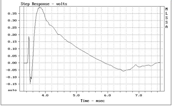
FIGURE 1: THOR step response.
Would it be possible to test the THOR loudspeaker (May '02 xyz) to provide a plot of the step response ” It seemed to me that Joe D'Appolito did the step response test for other speakers that he evaluated. To be consistent it would be nice to read his comments on the step response performance of the THOR and to see how it correlates to the excellent listening reviews that the THOR has received.
Fred Arikado Toronto, ON, Canada Joe D'Appolito responds:
Figure 1 is a plot of the THOR step response.
The THOR does not preserve time. (I do not consider this a problem, as there is no conclusive experiment on program material that shows it is audible.) The tweeter arrives before the woofers as you can see from the sharp initial spike. The woofers arrive later, but with the same polarity. The step response is very clean. There are no oscillatory wiggles.
MO' METAL SHARDS
Believe it or not, I just received some NOS tubes from AES in Arizona, and noticed that one CBS brand 6C8G had a 15mm × 8mm oval bare patch central in the “silver ” getter film. It has a peeling circumference. I've never seen the likes in 47 years of tube use. Not to worry.
I finished the little retro 1100mW/ channel headphone amp, and was testing upside down, voltage check, for example. But at full gain it slowly went into 1Hz motorboating-you know, positive feedback via the B+ rail (which sounded very interesting through quality headphones, by the way).
Suddenly, a click, and it stopped. And I traced the fault to a plate-to-grid short in one of the preamp 6C8Gs. I replaced the tube, and all was OK. Next day I noticed that it was the hole-in-the-wall tube that had shorted during the big voltage swings of motor boating. And, sure enough, tilting the tube revealed a heap of metallic slivers sliding about! And guess what ” They follow a neodymium magnet held close! Magnesium must be paramagnetic. I shook them all into the bottom and the tube now works fine.
So there you have it: big progress in the mystery, recently featured in these pages, about the presence of metal fragments in vacuum tubes, waiting for large signal-voltage swings to shimmy them over to a maximum field point- then zap. Who would have guessed that it could be getter-peel, most usually in tiny amounts ” Has anyone else ever seen an obvious hole in a shiny getter layer ” It actually looks like a hole in the glass! Jim Carlyle chrisjim@e3.net.nz SONIC COMPARISON Dennis Colin's proposal to test for euphonic coloration in power amplifiers (Dec. '04 xyz, p. 40) is both promising and intriguing, but I must take exception to both his method and his methodology.
To avoid unnecessary negativity and conserve space for more constructive proposals, I will summarize my objections to the method in the article: 1. it is not true that the properties of the reference amp itself are unimportant; 2. the reference amp load adds additional nonlinearities; 3. the amplifiers are operated at different stress levels [Fig. 3]; 4. an attenuator network will load both the amplifier and the speaker differently [Fig. 1]; and finally, using two different speakers is problematical.
Mr. Colin needs to define what he considers to be a neutral reference amp-all amplifiers are colored to some extent. The reference amp he uses is, by its nature, high in even-order distortion, has its own distinct (single-ended) coloration, and is severely limited in power.
(I assume the figure “15W/8 ” load ” is an error.) A unit under test (UUT) may be helped or hindered by the even-order harmonic distortion of the test amp if it has significant even-order distortion itself. Another problem is that the different distortions and euphonic colorations of both amps blend, forcing the listener to judge how much more distorted or euphonic the UUT is than the reference amp. If the UUT is less distorted, the listener has a real problem. Finally, be cause the UUT does not see a normal input, we have no idea what the amp will sound like in normal use. The results are peculiar to Mr. Colin's own system.
There are three basic test methodologies. They are-in order of desirability- cancellation, iteration, and comparison.
Figures 1 and 3 use comparison, which begs the question, “compared to what? ” The other two methods do not have this drawback.
In Fig. 2, Mr. Colin uses the cancellation method, but he devotes just one scant paragraph to the results. His basic problem seems to be inaudibility of the error signal. This might be made more audible by using a second amplifier of no great distinction, since only the error signal is amplified. The fact that the error signal itself is so low does not necessarily mean that it is negligible, since the ear may require some of the original signal to detect it.
A similar situation exists in ham radio, where Morse code is inaudible unless an additional signal is provided by the radio receiver.
The final method is iteration. A test signal is passed through two UUTs in tandem. The error signal is therefore the product of the distortion of either amplifier. By comparing the output of UUT 1 with UUT 2, any existing coloration is more easily heard. This method is ideal for testing stereo amps since a second channel is readily available, the power supply undergoes maximum stress, and the second channel is given “something to do. ” Note that this method does not make the distortion twice as audible. It works best with amplifiers with significant amounts of distortion, so sensitivity may be a problem with this method as well.
Clearly, there is much work to be done in this area. If anyone has had any experience with either the cancellation method or the iteration method, I would very much like to hear from them. I would be more than glad to share my own meager experience, and I look for ward to hearing Mr. Colin's further results. The ear is unique as an analytical instrument: not only does it grow more adept with personal experience, but with the experience of others, as well.
Bob McIntyre
Dennis Colin responds:
I appreciate Bob McIntyre's comments regarding the potential error sources, since I'm well aware of them and welcome the opportunity to further expound thereupon (they were introduced in the article). But first I'd like to clear up a fundamental methodological misunderstanding: What's labeled “Reference Amp ” in Fig. 1 I actually called “Auxiliary Amp ” (as in Figs. 2 and 3, and referred to in the first text sequence). While “just a typo, ” the significance changes dramatically: This amp is not intended to serve as an “amplifier sound reference. ” Rather, it functions as an impedance buffer, considered part of the audio source, whose function is to be able to drive speaker-level impedances. Thus (ideally, with the afore mentioned corruption errors rendered insignificant, if possible) one is not comparing the UUT with some “reference ” amp; you are comparing the UUT's input (I hope sufficiently consistent with switching) with its output.
Provided the auxiliary amp (1) is transparent enough to not obscure incoming detail, and (2) is consistent enough with switching (hence the second “dummy load ” speaker), then the auxiliary amp's properties simply add to those of the entire previous audio signal chain.
Mr. McIntyre said “Figs. 1 and 3 use comparison--compared to what? ” Yes, but what's compared are the UUT's own input versus output signals. I'd like to elaborate on Fig. 3. First, a correction/apology: There's no need for the UUT load to match that of the auxiliary amp; the UUT load is the speaker desired to be used with the UUT, and the auxiliary amp can drive any (high-quality) speaker or headphones (the latter, if acoustically isolating, would help in the necessary isolation of the UUT load speaker).
My original preference for Fig. 1 was based on my desire to have the UUT direct ly drive the auditioned speaker. But after some thought, reinforced by Bob McIntyre's objections to loading difference anomalies, I think Fig. 3 has the potential for accurate UUT in/out comparison: (1) Neither amp's load changes, and (2) the high-Z inputs of the auxiliary amp and the UUT output attenuator (say, 100k-ohm) will not significantly color or load the UUT input or output signals. Any (slight) attenuation of the input (from, say, a 1 k-ohm source) is taken into account during the A/B level-matching process. It should then be obvious that the UUT output signal, while driving a “real-world ” speaker, is being compared only with the same UUT's own (and unaffected by switching) input signal.
By the way, “15W/8 ” load ” is an error: “15 ” should be dimensionless; it is the damping factor. One last point: Despite the corruption potential of the Fig. 1 test I re ported on, the UUT in/out differences were on the edge of my perceptibility, at most.
My hearing is good (see notes at end of article); however, it extends to “only ” 15kHz.
I recognize that one with hearing to 20kHz might hear things I didn't.
In conclusion, I would now recommend Fig. 3 (I'll repeat the test on my tube amp with this setup). This test setup not only does not suffer from changing loads; it also doesn't impose power limitations on the UUT. Furthermore, the UUT is connected directly between the audio source and a speaker, as per normal usage. The only drawbacks (regarding method, not methodology) are (1) the need to acoustically isolate the UUT load speaker, and (2) the fact that you aren't directly listening to the UUT speaker. But regarding the latter, you are listening only for UUT in/out differences, so the auxiliary amp/speaker that does the “sniffing ” should be very transparent , but “perfection ” is not at all necessary. After the UUT input is listened to long enough to be accepted as the sonic reference, switching to the UUT output will reveal changes made by the UUT. But please note again: By “reference ” above is not meant the properties of the auxiliary amp/speaker or headphones: These properties are imposed in common to both switch positions; a “perfect piece of wire with gain ” UUT would show no differences. I thank Bob McIntyre for his insightful letter.
PREAMP BOARDS
I found the high-end preamp by Benjamin Hinrichs (Feb. and March xyz) most interesting and I would very much like to build it. In past years I have enjoyed reading about projects in Glass Audio, Audio Amateur, and Speaker Builder, and if boards were available I often purchased them and parts to build for my collection. I have built from all of Joe Curcio's articles, as well as the Cleveland and Last PAS, and the Pass A-40, to name a few.
Can you tell me how to obtain boards, or at least to obtain full-size layouts for the circuit ” I tried going to the Elektor site to find more information, but it appears you must subscribe in order to get the details.
Marshall Gordon
All Elektor circuit cards are available at www.elektor-electronics.00.uk. They are all preceded by the “at ” sign (@). Downloads are free. The boards may also be ordered through Old Colony on special order. The board numbers are as follows:
Drop-in microcontroller @ 020-148-1 $21.02 Main board @ 020-046-1 $20.66 Relay board @ 020-046-2 $18.33 PSU board @ 020-046-3 $16.38 Disks Sample project file @ 020-148-11 $18.30
Part 2 @ 020-046-11 $18.30 Hardware PIC18LF452-I/L, programmed @ 020-046-41 $68.90
HELP WANTED
I have several old reel-to-reel tapes of valuable lectures that are troubled with serious 120Hz hum and upper frequency hash. I intend to build a bandpass filter to rescue the voice of the male lecturer, but am uncertain of the optimum upper and lower cutoff frequencies and the roll off rates to use.
Might someone advise me?
A.J. Steen, 601 N. Kirby St., Sp. 71 Hemet, CA 92545-5910
Can anyone report on satellite radio as a possible audiophile-quality source of programming ” Which of the two competing services is better in terms of sound fidelity ” Are the component tuners better than the car/home docking types, even if the docking type is directly line-level audio fed to a good amplifier/speaker system ” Michael Kiley mikejkiley@juno.com Readers with information on these topics are encouraged to respond directly to the letter writers at the addresses provided.
-Eds.
--------
[The discussion above is adapted from an article, Jun 2005, outlined in xyz ]
Also see: