By Timothy Smith
This small amplifier provides about 20 very sweet watts per channel from a simple circuit based on 12BZ7 and 12BH7 input and E34L output tubes.
This amp design (Photo 1) is based on inexpensive, readily available parts and should be a good project for a novice or intermediate level builder. Assembly cost should be below $400. However, it offers a level of performance that should satisfy critical listeners, and would be a good foundation for a system based on high efficiency full-range drivers or horn-loaded systems.
PENTODE OPERATION
Unlike most other tube amplifier projects featured in audioXpress and its predecessor, Glass Audio, it operates its output tubes in pentode mode. There may be some concern about this, but many of the finest tube amplifiers ever built used pentode output stages, including the famous MacIntosh unity coupled designs such as the MC 275, the Carver Silver Seven, and the Quick silver M135. Additionally, nearly all of the tube-powered integrated amplifiers and receivers of the so-called “Golden Age” of stereo (such as Scott, Fisher, and Pilot) used pentode-connected EL84s, 7189As, or 7591As in their output stages.
Some of these units are considered among the smoothest-sounding amplifiers ever built. Most of these units produced between 15-20W/channel (EL84/ 7189A output tubes) or 25-35W/channel (7591A output tubes), so the amplifier described in this article is in familiar company. Most of the well-known out- put tubes (6V6, 6L6, EL84, EL34, 7591A, 6550, KT88, and KT90) were originally designed for pentode operation.
And, yes, there's more. The highly acclaimed Joe Curcio modification of the Dyna ST70 (GA 1/89, pp. 1-14) has a pentode-configured output stage. But for those who still balk at pentode operation, you can easily configure the amplifier for ultralinear or triode operation, as described later.
Most concerns about pentode operation center on higher plate impedance than triode or ultralinear operation (which corresponds to higher output impedance) and greater distortion sensitivity of the output stage to impedance variation in the speaker load. However, when well matched to the output load, distortion for most commonly available output tubes in pentode operation can be low, on the order of 2-5% before application of negative feedback. The real advantage of the pentode connection is increased plate efficiency and matching power output (and sense of impact), about 25% greater than for the ultra linear connection, and 50-60% greater than the triode connection. The lack of a stable, heavily filtered screen supply is a significant failing of many pentode de signs, especially in the past, but this de sign incorporates a very robust screen supply.
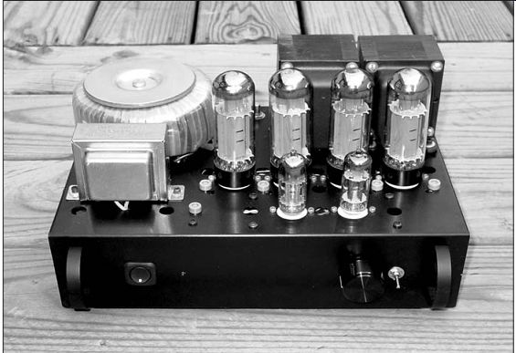
PHOTO 1: 20W per channel amplifier. Note pin jacks near each output tube, and ground pin jack near amplifier front. Bias pot shafts are visible to rear.
The high output impedance of a pentode-connected output stage, which translates to lower damping factor, can be used to advantage when driving high-efficiency drivers such as the Fostex FE206E which have inherently low values of Qts. Essentially such an amplifier acts as a current source which appears to provide optimum operation of these drivers, giving a bass boost and overall fullness that would not be available from amplifiers with higher damping factors (Pass, Oct. '04 xyz, pp. 6-13).
INPUT STAGE
The input and splitter stage (Fig. 1, Table 1) is based on single 12BZ7 and 12BH7 dual triode tubes; each channel uses one triode section of each tube.
The input starts with a simple four RCA jack input board and DPDT switch to allow for two different sources. A shielded four-conductor cable is used to connect the jack board to the switch.
Output from this switch is fed to P1, a dual 50k audio pot that serves as the amplifier's volume control. The wipers of this pot are fed to the plates of the 12BZ7 input tube through grid-stopper resistors R1 (150 ohm) for each channel.
The 12BZ7 is a low plate resistance version of the 12AX7 and is no longer in production, but appears to be readily available. It has a theoretical gain of 100, same as the 12AX7; in this circuit it provides an actual gain of about 70. Input for each channel uses one of the tube's two triodes. This causes very slight crosstalk between channels, but sufficiently low in my opinion not to pose any problems. The plate output of each triode is fed directly to the grids of the 12BH7, which is connected as a concertina splitter (the 12BH7 is readily available as a NOS item and is currently in production by Sovtek). The 12BH7 cathodes and plates are connected to ground and high voltage supply by resistors R6 and R7 (22 k-ohm, 3W), which are matched to within 1% for closely matched split output wave forms (minimum second harmonic distortion). The 12BH7 cathodes and plates are capacitively connected to the control grids of the E34L output tubes.
The 12BH7 does not provide any gain in this configuration, so all of the gain in the input stage is supplied by the 12BZ7 input section.
I used these two tube types because they provide low plate impedance, which provides best power transfer (gain) to subsequent stages. Also, both have 300mA, 12.6V filaments, so they can be operated with their heaters connected in series from a 25.2V AC filament transformer (more on this in the power supply section). If you want, you can use the 12DW7 (a tube that contains a 12AX7 and 12AU7 triode), currently in production by EI in Serbia, with slight modifications to the resistance values shown in the schematic, but I have not tried this tube.
OUTPUT STAGE
The output stage (Fig. 1, Table 1) is based on the reliable, musical, and in expensive JJ E34L tubes that were re viewed very favorably in Vacuum Tube Valley (Issue 16, 2001, pp. 29-31). Order a matched quad of these tubes for best performance. The tube plates receive B+ voltage from the output of the power supply; the screens are supplied with a B+ voltage that has been filtered by a large value choke and additional capacitance. The tube cathodes are connected to ground by R12 and 13 (10 ohm 0.25W), which provide modest local feedback and a way to measure idle plate current by means of tip jacks connected to each of the output tube cathodes.
These resistors also serve as fuses for the output tubes in that they will fail if any tube goes into a severely under biased condition, as would be caused by a grid to cathode short. The input grids of the output tubes have grid stopper resistors R10 and 11 (2.7k-ohm) to control possible oscillation; similarly the screen grids use grid-stopper resistors R14 and 15 (470 ohm, 3W). Overall negative bias for the control grids is supplied through resistors R8 and 9 (160k-ohm) from the bias control pots (P1 and 2, Fig. 2). These resistors are connected to the junction between the grid stopper resistors and the plate/cathode capacitors from the 12BH7 splitter tube.
The output tube plates are connected to the blue and brown plate leads of the Hammond 1645 output transformers; the transformer screen leads (blue/yellow and brown/yellow) are not used.
This compact transformer is rated for 30W (30Hz-20kHz ±1dB) so it is ad equate for this application. The output leads of the transformer are connected to S2 for 4 or 8-ohm operation only; the white 500 ohm lead is not used. S2 is a four-pole, two-throw toggle switch used to change between 4 and 8-ohm operation (and corresponding feedback compensation, see below).
POWER SUPPLY
This amplifier uses a simple, rugged power supply based on three separate transformers (Fig. 2, Table 2). At first, this configuration may seem clumsy,
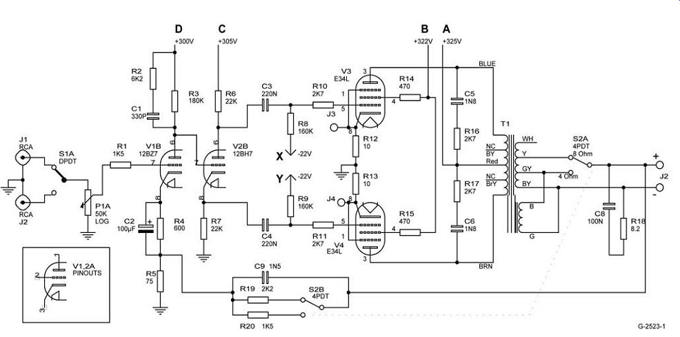
FIGURE 1: Amplifier circuit, one channel only.
=======
TABLE 1: Amplifier parts list and suppliers (one channel unless otherwise noted).
Part Value Vendor Part number
R1 150 ”, 1%, 0.5W Mouser 273-150 R2 6.2 k-ohm, 1%, 0.5W
Mouser 273-6.2k R3 180 k-ohm, 5%, 3W Mouser 283-180k R4 600 ”, 1%, 0.5W Mouser 273-600 R5 75 ohm, 1%, 0.5W Mouser 273-75 R6, 7 22 k-ohm, 5%, 3W Mouser 283-22k
(match to 1 %*) R8, 9 160 k-ohm, 1%, 0.5W Mouser 283-160k R10, 11 2.7 k-ohm, 1%, 0.5W Mouser 273-2.7k R12, 13 10 ”, 1%, 0.25W Mouser 271-10 R14, 15 470 ”, 5%, 3W Mouser 283-470 R16, 17 2.7 k-ohm, 5%, 5W Mouser 285-2.7k R18 8.2 ”, 5%, 5W Mouser 285-8.2 R19 2.2 k-ohm, 1%, 0.5W Mouser 273-2.2k R20 1.5 k-ohm, 1%, 0.5W Mouser 273-1.5k C1 330pF mica, 500V Digi-Key 338-1045-ND
C2 100µF, 25V Digi-Key 4032PHCT-ND C3, 4 220nF film, 400V Digi-Key P12107-ND C5, 6 1.8nF film, 800V Digi-Key P12432-ND
C7 100nF film, 630V Digi-Key P3521-ND C8 1.5nF film, 400V Digi-Key P3152-ND P1 50k dual audio pot Mouser 31XP405
(handles both channels) T1 30W, 5k-ohm
Angela Hammond 1645
output transformer V1 12BZ7 AES 12BZ7 V2 12BH7 AES 12BH7 V3, 4, 5, 6 JJ E34L matched quad AES JJ E34L
(V1-V6 handle both channels) S1 2P2T toggle
Radio Shack 275-636 S2 4P2T toggle Mouser 611-7401-001 S3 (optional**) 4 pole, 3 position Mouser 10WW043
(S1, S2, and S3 handle both channels) J1 4 phono jack board AES S-H311
(handles both channels) J2 Output terminals Radio Shack 274-718 J3-6 1/4 ” tip jack (blue) Mouser 530-105-0810-1
(handles both channels)
* Purchase 10-20 resistors and match two pairs with a DMM
** For switching from pentode to ultralinear to triode operation; see text
-------------------
but the individual transformers are in expensive and serve their respective purposes well. The B+ (high voltage) is supplied by a robust (225 VA) Hammond toroid transformer (pn 182J240), which is raised slightly from the chassis by plastic self-adhesive feet to provide clearance for the primary and secondary wires. Output from this trans former (240V AC) is rectified by D1, a 1000 piv 4A bridge, and filtered by a ladder of capacitors, resistors, and choke.
The first capacitor in the ladder is C6, a 10nF film capacitor that serves to lessen HF noise from the rectifier bridge. This is followed by C7 (820µF), which filters B+ voltage for the output tube plates. Then comes a large value choke L1 (10H, 100mA) and C8 (470µF), which supply heavily filtered and stabilized B+ to the output tube screens required for good pentode operation. This section is followed by two resistor capacitor pairs (C8, 100µF - R2, 510 ohm, 3W, and C9, 100µF - R3, 4.7 k-ohm, 3W), which supply B+ to the 12BH7 and 12BZ7 tubes.
The end of the filter ladder contains a resistive divider composed of R4 (300k-ohm) and R5 (100k-ohm), which sup plies about 75V to bias the AC filament supply. The large VA rating of the toroid transformer allows high idle currents (about 60mA per tube) with little voltage sag. This contributes to good low-power distortion performance for the amplifier.
The tube filaments are powered by a Radio Shack 25.2VAC 2A transformer (pn 273-1512). The output and input tubes filaments are wired in series and are biased by the previously mentioned resistive divider in the high voltage supply to minimize hum injection from the AC filament supply. Additionally, the lower leg of the resistive divider is bypassed with a low value film capacitor that helps filter noise out of the filament supply.
The bias supply and indicator LED are supplied from a negative voltage doubler fed by a small Radio Shack 12.6V AC transformer (pn 273-1365). Output of the doubler is about -34V, which is fed to a pair of ganged 10k pots, one for each channel. The ganged pots are wired in reverse to each other, so rotation of the pot shaft increases bias voltage for one tube while reducing it for the other. The overall range for bias voltage is set by R10 (100 ohm) ahead of the two pots and R11 (2.4k-ohm), which connects both ganged pots to ground. Output tube bias is set by measuring the voltage at pin jacks located near each output tube and rotating the control for similar voltage values for each tube of a push-pull pair.
HF COMPENSATION AND FEEDBACK
The amplifier uses three separate HF stabilization networks to ensure stability into essentially all loads. These networks also provide a well-behaved square-wave response, as indicated by the square-wave responses in Photo 3.
The first of these consists of R2 (6.2k-ohm) and C2 (330pF) capacitor in parallel with each of the 12BZ7 plate resistors.
The second is a snubber network across the output transformer primaries that consists of R16 and 17 (2.7k ohm, 5W) and C5 and 6 (1.8nF, 800V). The last is a zobel network of R18 (8.2 ohm, 5W) and C7 (100nF) placed across the loudspeaker terminals.
Modest local feedback is provided by unbypassed resistors on the 12BZ7 (R5, 75 ohm) and EL34 cathodes (R12 and 13, 10 ohm). R19 (1.5k-ohm) and R20 (2.2k-ohm), switch-selectable for 4 or 8 ohm loads, provide about 11dB of global feedback from the positive loudspeaker terminal to the 12BZ7 cathode at the junction of resistors R5 and R6.
R19 or 20 are selected by the four pole two-throw toggle switch (S2) that is also used to match the amplifier to 4 or 8 ohm loads. This switch is small, so wiring it can be difficult (Fig. 3). I recommend reading glasses and a nearby work light (I attached the output transformer leads with small dabs of solder; they're too large to fit into the switch lugs). I initially built the amplifier for 8 ohm operation only because most of my speakers are near 8 ohm impedance, and the 8 ohm connection on the Hammond output transformer uses all of the trans former's wire. However, 4 ohm operation of the amplifier is also very good and increases its overall usefulness. R20 and 21 are paralleled by C8 (1.5nF), which provides additional HF stabilization.
INITIAL ASSEMBLY
I think that you should have at least a good digital multimeter (DMM) and 5 or 10A Variac (variable autotransformer) on hand before building this or any other tube-powered project. A good DMM should cost about $75 or so, and the Variac about $100-125. You can purchase both at local electronics sup ply stores or national outlets such as Parts Express.
The Variac is indispensable for testing and power-up. It allows gradual power-up, which is best for testing circuits and forming electrolytic capacitors. Gradual power-up is a great way to minimize smoke and sparks from wiring errors (been there, done it!).
I built this amp on a small 8 × 12 × 3 ” chassis because I had one available (Photo 2), but I think that this is too small and recommend a 10 × 12 × 3 ” or 10 × 14 × 3 ” unit, which would provide enough room for easy wiring.
I wouldn't use a larger chassis, which would involve long wiring runs with increased susceptibility to noise.
I used a drill press and bi-metal hole saws to cut the larger holes (tube sockets-7/8 ” for the input tubes and 1 ¹/8 ” for the output tubes). I also cut seven holes in the amplifier base plate (Photo 4)
with the 1 ¹/8 ” hole saw. I used a ³/4 ” hole saw for the power switch on the amplifier's front panel and a saber saw with a sheet metal blade to cut out the opening for the AC inlet (I used a separate fuseholder, but recommend the integrated AC inlet and fuseholder listed in Table 2). Because of the small chassis, I simply glued the large power-supply capacitors (C7, 8, 9, and 10) to the underside of the chassis with automotive silicone gasket cement (the type that smells like vinegar).
I made sure that the glue would bond well by sanding both the capacitor base and its location on the chassis. With a larger chassis, you could mount these with capacitor clamps and allowed them to stand up through the chassis.
I used Black and Decker pilot-point drills for holes ¹/2 ” and smaller and wood blocks to support the chassis while drilling all of the holes. I drilled /8 ” holes behind each output tube and ¹/4 ” holes in front of each output tube socket for cooling, and a single ¹/4 ” hole near each output tube socket for pinacks that you can use for setting bias levels. I also drilled a ¹/4 ” hole near the power supply for a ground tip jack.
---------------
TABLE 2: Power supply and chassis parts list and suppliers.
Part Value
Vendor Part number
R1 160 k-ohm, 5%, 3W Mouser 283-160k R2 510 ohm, 5%, 3W Mouser 283-510 R3 4.7 k-ohm, 5%, 3W Mouser 283-4.7k R4 300 k-ohm, 5%, 1W Mouser 281-300k R5 100 k-ohm, 5%, 1W Mouser 281-100k R6, 7 1 k-ohm, 1%, 0.5W Mouser 273-1k R8 470 ”, 1%, 0.5W Mouser 273-470 R9 5.1 k-ohm, 1%, 0.5W Mouser 273-5.1k R10 100 ”, 1%, 0.5W Mouser 273-100 R11 2.4 k-ohm, 1%, 0.5W Mouser 31VC401 P1, 2 10 k-ohm dual linear pot Mouser 31VC401 C1 10nF disc, 220V AC Digi-Key P11423CT-ND C2, 3, 4, 5, 6 10nF film, 630V Digi-Key P3509-ND C7 820µF, 400V Digi-Key P10674-ND C8 470µF, 400V Digi-Key P10152-ND C9, 10 100µF, 400V Digi-Key P10136-ND C11 100nF film, 630V Digi-Key P3521-ND C12, 13, 14, 100µF, 63V Digi-Key P5582-ND 15, 16, 17, 18 J1 1/4 ” tip jack (green) Mouser 530-105-0804-1 D1 4A, 1000 piv bridge Digi-Key KBL10-ND D2, 3 3A, 1000 piv Digi-Key 1N5408GICT-ND LED1 T-1 (3mm) blue Digi-Key 67-1747-NDJ T1 117V AC primary, Angela Hammond 182J240, 240VAC secondary, 940mA T2 120V AC primary, Radio Shack 273-1512, 25.2V AC ct secondary,
2A T3 120V AC primary, Radio Shack 273-1365
12.6V AC ct secondary,
450mA CL1 CL-60 inrush limiter Mouser 527-CL60 S1 SPST rocker Radio Shack 275-693 Chassis 12 ” × 10 ” × 3 ” or Mouser 563-AC-413 (select one) 14” × 10” × 3 ” Mouser 563-AC-414 Base plate 12 ” × 10 ” or Mouser 563-BPA-1523 (select one) 14” × 10”
Mouser 563-BPA-1524 AC connector and fuse holder Mouser 161-PF0001/28 F1 3A slow blow Mouser 5765-18316
(5 × 20mm) Terminal strips AES P-0601H02,
P-0702H, P-0802H
(5 per pack, should be enough)
Knob Volume control
Mouser 450-7016
Feet screw-on plastic feet local hardware store
-------------------------
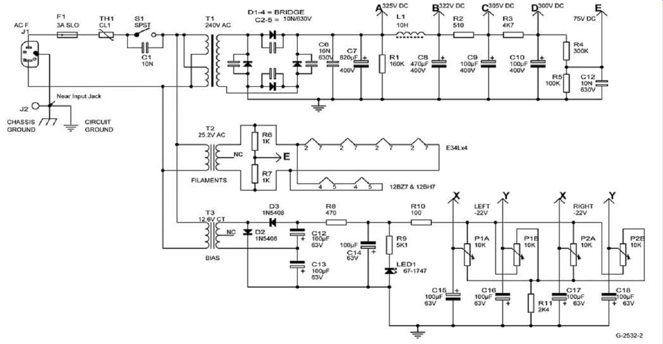
FIGURE 2: Power supply.
For wiring, I used tube sockets and terminal strips, which are available from Antique Electronic Supply and your local electronics store. Most of these will have lugs that provide direct connection to the chassis; you can use these for ground connections.
I had my chassis anodized so I used 14-gauge copper bus wires for circuit and power-supply grounds. This technique works well. All of the bus wires are connected to a single ground lug at the chassis rear, near the input jacks (I sanded the anodized coating off to provide good electrical contact with the chassis). The power cord ground line is connected to this chassis ground.
Overall assembly is straightforward.
I wired the amp in three successive stages: power supply, then input stage, and finally the output stage. Do not in stall the E34L output tubes at this time. I tested each stage with the Variac and DMM to make sure that it worked well before proceeding to the next stage. All wiring runs should be as short as possible (to minimize noise). The filament wiring should be twisted and pressed f lat against the chassis. I used 20-gauge stranded wire, color coded for purpose (red for high voltage, purple for negative voltage, green for ground, yellow and blue for filament voltage, black for AC mains voltage, and orange for low voltage). This makes it easy to identify individual circuits within the amp.
I twisted the filament voltage wires with a drill; two and a half to three twists per inch should be adequate. Greater twist density will likely result in insulation damage.
I used a 60W pencil soldering iron to ensure good solder joints, and repeatedly shook the chassis or blew it out with compressed air to remove sol der balls and splashes that otherwise inevitably end up causing spectacular shorts on power-up. Visually check every solder joint to make sure that it is good, and that there are no solder bridges to ground or between terminals or tube socket connections. I used a Radio Shack solder sucker (pn 64-2098) to remove excess sol der, and reading glasses and a small flashlight to check out my soldering work.
As with any electronic project, safety should be the primary concern. This amplifier utilizes voltages that can cause injury or death. Always measure voltages with one hand in your pocket, or use rubber garden gloves.
It's a good idea to use an alligator clip ground lead for the DMM and probe type positive lead. This configuration enables easy one-hand measurement of circuit voltages. Conversely, you can use the chassis-mounted ground tip jack for the DMM negative lead. Always think twice when working on an energized circuit!
FINAL ASSEMBLY AND POWER-UP
Once you are certain that the circuit is properly wired and the voltages shown on Figs. 1 and 2 are present, it's time to
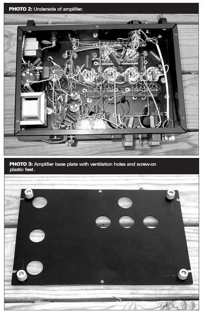
PHOTO 2: Underside of amplifier. PHOTO 3: Amplifier base plate with ventilation holes and screw-on plastic feet.
be brave and install the output tubes and set the bias. Be certain that the negative bias supply is working. Set each bias supply dual pot (P1 and P2) to mid rotation; at this point, pin 5 of each EL34 socket should register about -22V. Turn the power off, remove the power cord, and wait at least 30 minutes before proceeding (this enables the power-supply capacitors to drain completely). Make sure that the output transformer blue and brown primary leads are connected as shown in Fig. 1 (Blue is connected to the tube that is fed by the 12BH7 plate, and brown is connected to the tube that is fed by the 12BH7 cathode). Connect an 8 ohm 10 to 20W power resistor across each set of speaker terminals, install the E34L tubes, set the volume control to minimum, and power up. Watch for any tube whose plate glows red; you should discard such tubes. This event is very rare and is not expected.
Insert the negative and positive DMM probes into the pin jacks for each pair of output tubes and rotate the bias pot for that pair to achieve a near 0V DC reading. You will need to repeat this procedure a few times before the output tubes stabilize. You should be able to set the voltage difference between the tubes of each output pair to about 0.02V or less. If not, try installing the output tubes in different sockets.
You should be able to minimize the voltage difference between tubes with the use of a matched quad, or two matched pairs. Then check for idle current by placing the negative DMM probe into the ground pin jack that was installed near the power supply.
This should register between about 0.6 and 0.8V DC, corresponding to 60 80mA of idle current. Check for errors in the bias circuit if you do not observe these values (if your tubes draw near 80mA and are stable, you may choose to change R11 from 2.4 to 2.7k-ohm). Once the bias settings are stable (about 10 minutes of operation), turn the power off, disconnect the 8 ohm power resistors from the speaker terminals, and connect the line voltage sources of your choice (CD, tuner, and so on) to the inputs, speakers (preferably disposable types) to the outputs, and set the impedance selector switch to match the speaker impedance.
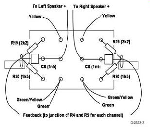
FIGURE 3: Wiring details for S2, impedance/feedback selector switch. R19, 20, and C8 are connected to terminals near the switch.
Turn the amplifier on and set the volume low and listen. If the amplifier sounds very loud and ragged, or howls, turn it off, and make sure that the output transformer primary leads (blue and brown) are wired as described in
Fig. 1. If everything checks out well, hook up your regular speakers, set the impedance/feedback switch, and listen.
MEASUREMENTS
The amplifier's gain is about 26.5dB for the 8-ohm output, which means that a 0.6V signal is required for maximum power output (13V RMS into 8-ohm load); this enables its use as a simple “integrated ” amplifier for line-level sources (CD, tuner, video, and so on). Output noise on the 8-ohm tap with the input shorted is about 0.8mV RMS, which corresponds to a signal-to-noise ratio of about 84dB. This compares well with many commercial push-pull tube designs, and is significantly quieter than most single end designs that I know of. It produces about 20W/channel into either 4 or 8-ohm loads with slightly more than 1% distortion. The onset of visible distortion (usually about 3%) occurs at about 25W output.
The overall distortion characteristic of the amp is shown in Fig. 4, and its frequency response at 5W output is shown in Fig. 5. It rolls off smoothly at high frequency, and is down about 2.5dB at 20kHz. This may seem questionable for a high-fidelity amplifier, but in my biased viewpoint, it contributes to sweetness and lack of irritation in its sonic characteristic.
Note that this HF characteristic is common to many highly rated single end triode amplifiers, especially those with no global negative feedback. Its square-wave response at 3 and 10kHz, 5W into 8-ohm, is shown in Photo 3. Both responses are well-behaved with little or no overshoot at the square-wave leading edge.
The amplifier's output impedance is high, as expected, about 2.1 ohm at the 8-ohm tap, corresponding to a damping factor of 3.8. These values also correspond with those for many (or most) single-end triode amplifiers.
They also show that it acts at least somewhat as a current source amplifier as outlined by Pass in Oct. '04 xyz. The low damping factor may mitigate against the amplifier's use for vented speaker systems, or speakers with complex impedance curves (usually three- or four-way designs), but you should listen and see for yourself. The low damping factor may be helpful in sealed box designs, and is especially useful for high-efficiency speakers with low values of Qts. Again, the Fostex series of full-range drivers comes to mind with this amplifier.
ULTRALINEAR AND TRIODE OUTPUT
You can easily configure the
--------------
REFERENCES
1. Curcio, J., 1989, “A vacuum tube power amplifier with solid state regulation, ” GA 1/89, pp. 1-14.
2. Kittleson, C., 2001, “EL34 shootout for hi fi, ” Vacuum Tube Valley, Issue 13, pp. 29-31.
3. Pass, N., 2004, “Current source amps and sensitive/full range drivers, ” Oct. '04 xyz, pp. 6-13.
PARTS SUPPLIERS
Angela Instruments angela.com 301-725-0451
Antique Electronic Supply (AES)
tubesandmore.com
480-820-5411
Digi-Key digikey.com 800-344-4539
Mouser Electronics www.mouser.com
800-346-6873
TEST EQUIPMENT
Hitachi V-355 oscilloscope
Fordham AG 260 audio generator
Hewlett-Packard HP 334A distortion analyzer
Tektronix DMM 916 digital multimeter
B+K Precision 1805 frequency counter
Duncan Amplifiers PSUD2
power supply
program
------------------------
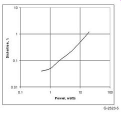
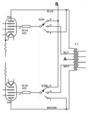
FIGURE 6: Wiring details for optional rotary switch S3 (switchable pentode-ultralinear triode operation), one channel only.
FIGURE 5: Amplifier distortion vs.
power output at 3kHz, 8-ohm tap.
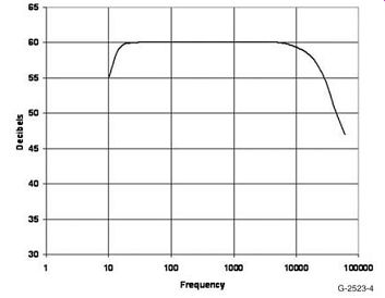
FIGURE 4: Amplifier frequency response at 5W, 8 ohm tap.
--------------
amplifier for ultralinear or triode operation if desired. For ultralinear operation, you can connect the disused ultra linear taps on the output transformer to the EL34 screen grids through the 470 ohm, 3W screen grid-stopper resistors.
Make sure that the ultralinear leads match the plate leads (blue/yellow and blue, brown/yellow and brown). You should tie the screen voltage line from C3 to an unused terminal. Output power in UL mode is about 16W. For triode operation, directly connect the plates to the 470 ohm 3W screen resistors.
Make sure that the plate is connected to the resistor and not the screen pin on the tube. Tie the ultralinear leads from the output transformers and the screen supply leads to unused terminals. output power in triode mode is about 10W. For those who are pretty enterprising, you can arrange a three-position four pole switch to select any of the three modes (Fig. 6).
LISTENING
As always, the proof is in eating the pudding. I liked this amplifier from the beginning. It has a sweet, melodic character, with enough power to drive speakers with about 90dB efficiency to room-filling levels. It overloads grace fully so it sounds more powerful than its rating.
It reminds me of a single-ended 300B amplifier on steroids. It sounds marvelous when used with full-range high-efficiency drivers; I think this is due in part to its gently falling HF response, which would tend to cancel the rising and somewhat ragged HF response of many of these units. I listen to most types of music and found it to be pleas ant, perhaps at its best with New Age piano (George Winston), jazz, and vocals.
If nothing else, it will give you an introduction to the sonic signature of many of the tube amps of yore, and you can then see whether this tube stuff is worth all the bother. Try it and see for yourself, I think you will like it. xyz
Tim Smith is a consulting geophysicist for Unocal in Sugar Land, Tex., and is involved in oil and gas exploration in the deep water portion of the Gulf of Mexico. He has been an avid audio hobbyist for over 30 years, and has been designing and building tube-powered hi-fi and guitar amplifiers for the last eight years. He has used many of his friends as guinea pigs for his designs, and is very grateful for their patience and comments. He can be reached at tsmith15937@msn.com.
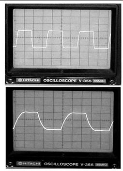
---------------- PHOTO 4: 3kHz (top) and 10kHz (bottom) square-wave response, 5W into 8-ohm load on 8-ohm tap.
[The discussion above is adapted from an article, June 2005, outlined in xyz ]
Also see:
Link | --Single-Ended to Differential-Mode Vacuum Tube Projects Made Easy