Cont. from: Electrostatic Loudspeaker Basics, Part 1 (June)
The author continues his detailed look at ESLs, comparing basic theory with test results.
By Matthew Lattis
AMPLIFIER LOADING
This brief, initial discussion of the load presented by a transformer and speaker covers the case of a transformer with an amplifier connected directly to the primary and a speaker connected directly to the secondary. Refer to Fig. 18's bottom pane for a typical impedance/phase plot of an ESL load measured at the transformer primary. At low frequencies the primary inductance of the transformer is the dominant factor influencing impedance, and most amplifiers have little trouble in this region. As the frequency increases, the capacitive reactance of the speaker begins to take a more prominent role in the final impedance of the system, and the electrical phase swings strongly capacitive in this region.
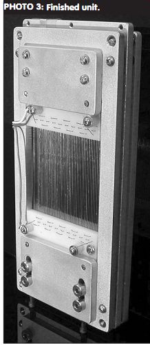
PHOTO 3: Finished unit.
Luckily, the impedance is still relatively high at these frequencies, and most amplifiers tolerate this kind of load as well. At high frequencies things become ugly as the leakage inductance of the transformer and the speaker load produce a series resonance and the impedance plummets. At this point the impedance is basically determined by whatever wire resistance is in the primary plus the secondary's reflected wire resistance. At the typically high frequencies involved, the demands for power (with music) are small, but some amplifiers are still very unhappy when presented with this type of load.
As a general rule, transformers with the highest step-up ratios are more problematic because the capacitance on the secondary of the transformer is multiplied by the step-up ratio squared when it is referred to the primary (e.g., 500pF on the secondary of a 1:50 transformer is 1.25µF when reflected to the primary). The leakage inductance is also normally higher with higher turns ratios, which causes the series resonance at high frequencies to occur at a lower frequency. Good transformer design and implementation can help to lighten the load for the partnering amplifier, though, and I will discuss that a little later. For a more thorough treatment of equivalent circuits and transformer testing, Ron Wagner's Electrostatic Loudspeaker Design and Construction is a good resource.
Figures 18-23 present a variety of typical transformers and wiring con figurations with no load, a 165pF load, and a 1060pF load. Electrical phase is the higher trace at 10Hz in each graph.
The approximate capacitance of an ESL can be computed with equation 3:
C = (0.224KA)/d (3)
where C = capacitance in picofarads
K = dielectric constant of the material between the plates (air = 1)
A = area of one plate in square inches
d = distance between plates in inches
The first transformer I will look at is a clone of the MagneTek Triad S-142A (I used a clone because the S-142A was discontinued before I started working with ESLs). Since this device was de signed for use as an output transformer in tube amplifiers, it is connected in re verse when used with ESLs (the prima ry is used as the secondary). This model presents a few wiring options using the full primary as a secondary and various secondary taps as the primary. I tested the following configurations:
Common – 4 1:44 ratio -Fig. 18
8 ohm - 16 ohm 1:76 ratio -Fig. 19
4 ohm - 8 ohm 1:100 ratio -Fig. 20
Next, two toroidal models from Plitron are shown. The PAT-4133-ES is a 1:50 unit whose results are shown in Fig. 21. The PAT-4134-ES has a 1:75 turns ratio and is shown in Fig. 22. The final transformer considered in these tests is the Tranex 2-0404, which has a 1:150 turns ratio -- Fig. 23.
A quick survey of the test results shows that the modern Plitron units provide the most extended frequency response of all the transformers tested and are an easier load to drive when similar turns ratios are involved. When compared to the S-142A clone wired for a 1:44 ratio, the PAT-4133-ES has significantly higher impedance at high frequencies and also has a 1.1dB advantage due to its 1:50 turns ratio. In the lowest pane of Fig. 18, you can see the impedance minimum at ~18kHz and the abrupt change in electrical phase in the same region which indicate the resonance formed by the S-142A's leakage inductance and the speaker capacitance. This resonance produces a low-pass filter that limits the high-frequency response of the system.
No sign of the Plitron PAT-4133-ES's resonance is visible on its plot with the same load (a resonance is still there, of course, but it is ultrasonic and, there fore, outside the range of the hardware used). With the 1060pF load the impedance of the 1:75 Plitron PAT-4134-ES is inconsequentially lower at 20kHz than the S-142A wired for 1:44, but the Plitron unit still has a bandwidth advantage. Though the phase is just starting to swing upward near 20kHz with the heaviest loading of the PAT-4134-ES, the actual resonance cannot be seen on this plot. The 1:75 ratio provided by the Plitron unit gives it a 4.6dB output advantage over the 1:44 of the S-142A (equivalent to nearly tripling amplifier power). When you compare the 1:75 Plitron to the S-142A wired for 1:76 with the heaviest loading, the Plitron's resonance occurs over an octave higher, and it has a moderate impedance ad vantage at high frequencies.
LIGHTENING THE LOAD
You can use two simple methods to make an ESL load less demanding. Neither approach will make the speaker easy to drive, but easier is possible without much effort and can make a significant difference if your amplifier is borderline. Both methods involve placing resistors in the circuit, so there are no detrimental phase effects.
Option 1: By dividing the speaker into smaller areas and using resistors between the transformer's secondary and the individual segments, you can produce low-pass filters that can be used to adjust frequency balance and to prevent the full capacitance of the speaker from being reflected to the primary at frequencies higher than the crossover point. This resistance is referred to as Res in the following treatment. It is Res/2 in the schematic because each resistor sees the capacitance formed from the stator-to-diaphragm. You should use plate-to-plate capacitance with Res or plate-to-diaphragm capacitance with Res/2 when calculating crossover points.
The low-pass slope is 6dB/octave with the -3dB point occurring where the capacitive reactance of the ESL segment is equal to the value of Res. The Quad ESL 57 and ESL-63 were some of the best known units to use this technique (the 63 also used a rather elaborate time delay circuit with ring-shaped segments in the central portion of the speaker to emulate a point source). You can use equation 3 to calculate capacitance, while equation 4 defines capacitive reactance Xc = 1/(6.283fC) (4) Xc = capacitive reactance in ohms f = frequency in hertz C = capacitance in farads Option 2: Placing a resistor in series with the transformer's primary also has several benefits and is highly recommended by Menno van der Veen, the designer of the Plitron ESL transformers. You can easily tune the Q of the series resonance formed by the speaker capacitance and transformer leakage inductance with this resistor to eliminate ringing in the speaker/transformer system. If necessary, you can also decrease the output at high frequencies with this resistor. Additionally, you can sometimes use this extra resistance to stabilize an amplifier that is having difficulties driving an ESL load.
The following treatments of ESL transformer theory were graciously supplied by Menno van der Veen. As stated earlier, transformer theory is also covered in Ron Wagner's Electro static Loudspeaker Design and Construction (please keep in mind that loads can be reflected to the primary or secondary side for analysis).
Figure 24 shows the basic components I have been discussing.
Rep is a tuning resistor in series with primary Res is a tuning resistor in series with secondary
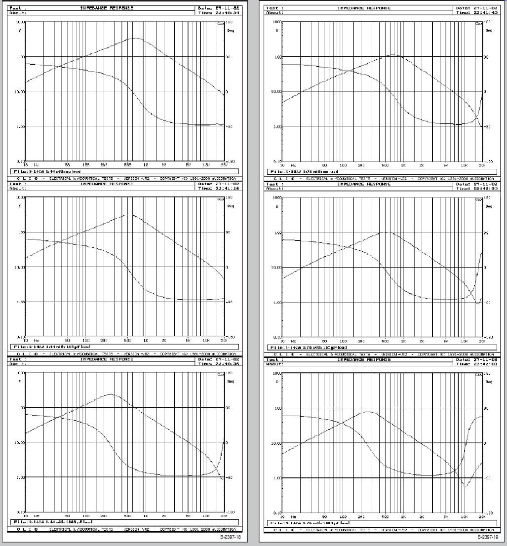
FIGURE 18: MagneTek Triad S-142A clone 1:44. FIGURE 19: MagneTek Triad S-142A clone 1:76.
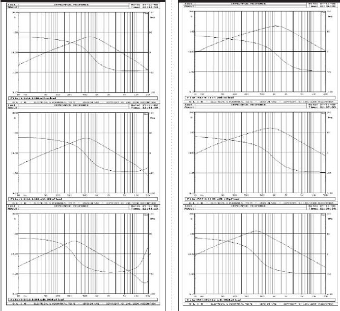
FIGURE 20: MagneTek Triad S-142A clone 1:100. FIGURE 21: Plitron PAT-4133-ES 1:50.
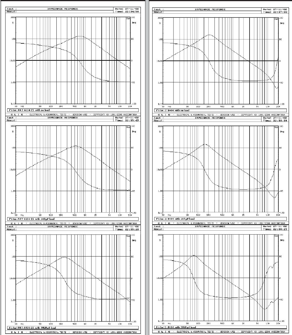
FIGURE 22: Plitron PAT-4134-ES 1:75. FIGURE 23: Tranex 2-0404 1:150.
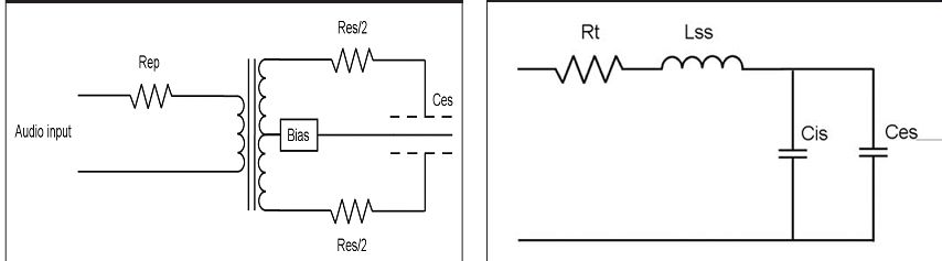
FIGURE 24: Basic ESL/transformer configuration. FIGURE 25: High frequency
equivalent circuit.
C_es is the capacitance of the electro static speaker from plate-to-plate If you omit Res to simplify the analysis, at high frequencies you are left with the equivalent circuit shown in Fig. 25 and covered in equations 5, 6, and 7. All of the relevant primary elements are reflected to the secondary side in this analysis.
L_ss is the leakage inductance of the transformer in henries C_is is the secondary winding capacitance of the transformer in farads C_es is the capacitance of the electrostatic speaker from plate-to-plate in farads Rt is a combined resistance reflected to the secondary and is defined in equation 5
Rt = (Ns/Np) 2(Zout + Rep + Rip) + Ris (5)
Ns = number of turns in the transformer's secondary winding
Np = number of turns in the trans former's primary winding
Z_out = output impedance of the amplifier in ohms
Rep = tuning resistor in series with primary, value in ohms
Rip = wire resistance of the trans former's primary in ohms
R_is = wire resistance of the trans former's secondary in ohms
The actual number of turns in the primary and secondary are not necessary; the ratio is all that is required in the calculation.
Equation 6 defines the resonant frequency of the low-pass filter formed by these components.
f = 1/(6.283(Lss (Cis + Ces)) ½) (6)
f = frequency in hertz capacitance is in farads and inductance is in henries
Equation 7 defines the Q of the circuit
Q = (1/Rt)(Lss/(Cis+Ces)) ½ (7)
For the best high-frequency extension with minimum phase shift and ringing, set the Q at 0.577. You could increase the Rep beyond this point to try to stabilize the partnering amplifier or to decrease high-frequency output.
The following points were also conveyed in correspondence with Menno van der Veen.
1. He suggested a maximum DC offset of 3mV from the amplifier to ensure that the transformer has adequate magnetic headroom during operation. As little as 10mV of offset can saturate the core.
2. At both the high-frequency series resonance and at very low frequencies, Rt is the major factor influencing the total impedance.
3. The use of Rep produces better DC offset behavior because part of the DC will be dropped across the resistor in series with the primary.
To demonstrate the benefits of using Rep, I conducted the following test using an inexpensive 45W/channel receiver that was known to be slightly unstable into electrostatic loads. I used a 100MHz Tektronix TDS 340A oscilloscope to gather the data presented in the graphs that follow. Figure 26 shows a 2kHz 1V peak to-peak square wave at the output of the receiver with no load. Figure 27 shows the input and output of a PAT-4134-ES driven with the same signal while the secondary was connected directly to a 1200pF ESL. The transformer's output trace has been rescaled to compensate for the 1:75 turns ratio. Rep was then added to the circuit to produce the graph shown in Fig. 28.
To tune Rep, I added a potentiometer to the primary side of the transformer and increased the resistance until the over shoot and ringing were eliminated. I kept the resistance as low as possible to retain maximum "squareness" in the output. In this case, 1.4 __ proved optimal.
Neglecting the output impedance of the receiver and any resistance present in test leads, you have a resonance of 24kHz and a Q of 0.38. The Q implies that the system is overdamped and that the high-frequency output will be rolled
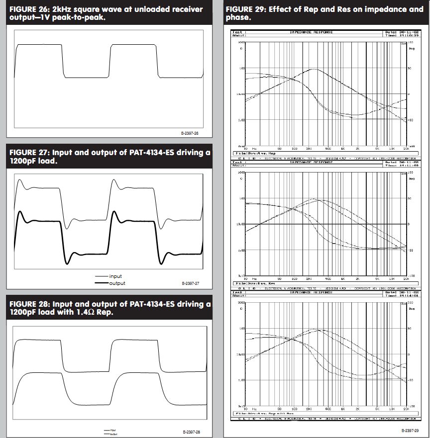
FIGURE 26: 2kHz square wave at unloaded receiver output-1V peak-to-peak.
FIGURE 27: Input and output of PAT-4134-ES driving a 1200pF load.
FIGURE 28: Input and output of PAT-4134-ES driving a 1200pF load with 1.4 ohm Rep.
FIGURE 29: Effect of Rep and Res on impedance and phase.
off from its theoretical maximum band width, but I will gladly trade that for the benefits the extra resistance provides for the receiver.
You can also see the benefits of Rep and Res as shown in Fig. 29. The top plot shows the original impedance and phase produced by a 1060pF load connected directly to the secondary of a PAT-4134 ES versus the same load driven with 2 ohm of Rep. The middle graph in the group shows the original load versus 500pF driven through 2.2M ohm of Res and 560pF driven directly. The Res provides a low-pass crossover at approximately 145Hz with a slope of 6dB/octave and helps to decrease the phase angle at mid frequencies.
The bottom plot is the original load versus both methods combined. The result of using both methods is still not the most benign load in the world, but the improvement is considerable.
CONCLUSION
I hope this article has answered more questions than it has generated. I'm still searching for the "ultimate" full-range ESL design that will convince me to dive demand its full-time use in my system.
I hope others will share their experiences in this forum. It's not just groundbreaking discoveries that need to be written about; patents and de signs that might initially seem out of date often contain many details that are still pertinent (and not widely known). If you've rediscovered the benefits of someone else's work and it hasn't been covered lately, please share with the group. __xYz
Thanks to John Triplett for the machine work-you can see some of his more ambitious endeavors at
nothingbutcustoms.com I also thank Galen Powers, who sup plied the equipment and talent used to photograph this project.
Matthew Lattis has been experimenting with ESLs for approximately 10 years and has had projects published in Speaker Builder and Audio Electronics. His current employer specializes in plastic ophthalmic lenses and systems for their production. Eighteen US patents cover
SOURCES
Old Colony Sound Lab PO Box 876 Peterborough, NH 03458 888-924-9465
Electrostatic Loudspeaker Design and Construction
The Audio Amateur reprints Audio Amateur Loudspeaker Projects Plitron Manufacturing Inc.
8-601 Magnetic Drive Toronto, Ontario M3J 3J2 Canada 1-800-PLITRON (1-800-754-8766)
Tranex 2350 Executive Circle Colorado Springs, CO 80906 1-800-886-5354
DesignTEQ 5325 Foundation Blvd. New Albany, IN 47150
812-941-0010
DesignTEQ specializes in prototype design and construction and low volume production. They provided CNC laser cutting for the tensioned wire speaker.
[The discussion above is adapted from an article, Jul 2005, outlined in xyz ]
Also see: