CORRECTION
I found an error in my article "The Double-Dipole Subwoofer," which was published in audioXpress, November 2004, p. 18.
In Fig. 12, the regulated power supply, the values of resistors R2 and R4 which adjust the output voltage of the voltage regulators, should both be 2k7.
George Danavaras Athens, Greece
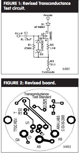
REVISED TEST
In response to inquiries about my re cent article ("A Transconductance Tube Tester Test Standard," Feb. '05 __xYz, p. 18), I have made several changes to allow the Transconductance Test Standard to work on higher input (grid signal) voltages, such as on some selected ranges of the Hickok Model 539 series.
Measurements on this standard were within ±1% of 1500µS with input signal voltages of up to 7.5V RMS and plate voltages up to 250V DC. This necessitated some modifications to the circuit as shown in Fig. 1.
I devised a new circuit board. Due to the power dissipated within this device at higher plate voltages, I've also included additional holes to attach a heatsink with standard 1.0” spacing between pins. I turned the heatsink down on a metal lathe such that the bottom 1.5” fit within a standard 1.25 " O.D., thin wall (0.050” wall thickness) tubing. I then fit the aluminum tube over the octal plug socket and potted using Loctite E-60NC Hysol epoxy potting compound. The outside of the case heated up approximately 30°C after 15 minutes of operation at 200V DC plate voltage.
Joel Hatch
---------------
Revised Transconductance Test Standard Circuit Board---single-sided (Fig. 2)
C1 = 0.15µF P10969 (Panasonic ECQ, 250V metal polyester) [Digi-key]
R1 = 250k-ohm (Vishay 1/4W) [Mouser]
R2 = 118- ohm (IRC Precision, 0.1%, 1/4W) [Mouser]
R3 = 511.2 -ohm (Vishay 1/2W, selected from 511 ohm 1% resistors, 509.5 to 512 ohm are suit able) [Mouser]
D1 = UF4004 (Vishay 400V, 1A rectifier) [Mouser]
D2, D3 = 1N5245B (Diodes Inc., 15V zener) [Digi-key]
U1 = 10M45S (IXYS) [Digi-key]
HeatSink = HS239 (Aavid Thermalloy 5300002B02500) [Digi-key]
Octal Base socket = Octal Socket Accessory #15 (QQQ Octal Pin Plug) [Angela Instruments]
Reference: Outside Circle Dia. = 1.100”, Bar adjacent to hole on diodes indicates cathode.
--------------------
TRANSFORMER SOUND
I read Norman Thagard's article about H.V. differential amplifiers in audio-Xpress ("Single-Ended to Differential Mode Made Easy," Dec. '04, p. 8) with great interest. Congratulations on your work. I never thought of connecting so many tube amplifiers in series/parallel to achieve such levels of power.
We (at Audio Consulting) are working on differential topologies for solid state and tube amplifiers. Although in both cases, power never exceeds 30W, the sonic advantages of differential topologies are quite obvious (at least to us), especially in these times when the audiophile community calls for single ended circuits. Here are two areas we would like to address:
Phase splitters. This is a very critical stage. We have tried many circuits- solid state and tube-and finally use transformers. We still believe that this is sonically the most satisfying way of producing 180° out-of-phase signals. The two out-of-phase signals are identical voltage wise and source impedances are identical, too. The latter is more important to sound performance than we initially may think.
Many topologies that are used to pro duce out-of-phase signals use different devices or a number of devices for each phase, which lowers the performance.
Of course, the quality of the transformer is absolutely crucial. It happens that transformers are our specialty and we have produced many different types that may be used to achieve 180° out-of phase signals: from low impedance to high impedance, with or without voltage gain, copper wire or silver wire, various magnetics, from regular 0.35mm grain oriented steel to extremely exotic materials in wooden cabinets.
Power from power lines to high power amplifiers. Your very original way of using standard tube power amplifiers and its advantages can also be applied to the utility mains. You mentioned that you were having mains voltage down to 107V AC when operating all your power amplifiers, showing the limitations of running 115V AC power lines where power is provided with high value AC currents.
In our constant battle for better-sounding mains, we have developed very special power supply and mains isolation transformers that allow for much higher energy transfer from the mains to the amplifiers. Today's mains quality is extremely bad for audio components, and this has nothing to do with sags, HF, or RF. But this is another story.
One transformer that we use for Europe and Asia has a 400V AC primary winding that allows it to be connected between two of the three phases we get in our homes. Mains here comes with three 230V AC lines that are out-of-phase by 120° and one "0" connection. Normal connections between the "0" and one of the three 230V AC lines lead to the standard 0-230V AC mains situation we have over in Europe and parts of Asia.
Using power between two out of the three 230V AC lines leads to 400V AC (v3 × 230V AC). Using power that way has the big advantage of avoiding the "0" connection, which carries the bigger part of the unwanted "pollution." Thus a 400-230V AC isolation transformer allows for a totally new and isolated 230V AC line feeding your audio system. There is a similar situation in the US.
In the US, 230-115V AC transformers work perfectly for homes having access to both 115V AC phases (out-of-phase by 180° here). The situation in the US re ally is a differential topology, by analogy to your way of using power amplifiers.
Sound wise, this also leads to big improvements, for reasons that would take another few pages to mention.
I really became excited about your work and we would be most happy to provide you with free samples of phase splitter transformers in case you are interested in further experiments. We just need to know the output stage topology and impedance of your preamplifier in order to produce an optimum phase splitter transformer. If the impedance is low enough, we may even consider volt age gain within the transformer.
Serge Schmidlin Audio Consulting; 14 B Chemin Des Vignes 1291 Commugny, Switzerland
Norman Thagard responds:
Thank you very much for your kind letter. It was the incremental improvement in reproduced sound noted with each increase in the number of amps that spurred me to find a way to maximize the power.
My reason for settling on the single-transistor phase-splitter was its excellent objective performance combined with simplicity.
I wanted to avoid additional active stages if I could.
In theory, transformers offer a superior method of converting a single-ended signal to a differential one, but as you note, transformer quality is crucial. Since I have some facility at electronic circuit design and none at transformer construction, I opted for the electronic approach to phase-splitting.
Some years ago I purchased a book on transformer design and construction, so I do have a pretty good idea how to go about it while preserving frequency response. I am still unmotivated to attempt it myself, as it looks like a fairly daunting task. Nonetheless, there are folks who can "roll their own," modify existing transformers, and/or re-wind defective tube amplifier output transformers, a capability that I especially admire.
I would love to compare the sound of a transformer phase-splitter with the one currently in my system, which is the MOS-FET-based version of the Concertina phase splitter as described in my article. For vinyl playback the phase-splitter is directly driven by the output of a two-stage MC cartridge phono preamp, which has a BiMOS folded cascode, single-ended (as opposed to complementary with push-pull action) output stage whose output impedance ranges from about 25 ohm at 20Hz to 10 ohm at 20kHz thanks to negative feedback. For CD, SACD, digital cable, tuner, and so on, playback, a Marantz preamp drives the phase-splitter.
I have no idea what its output impedance is, but would guess it's probably pretty low.
Since most of my listening is through the phono preamp, I would have a greater interest in a transformer optimized for the MC phono preamp. The differential input resistance of either channel's tube amp complement is 0.5-ohm . Of course, my single-transistor phase-splitter outputs each drive four paralleled input channels of the tube amps and therefore "see" a single-ended resistance of 250k ohm.
Again, I appreciate your kind letter and your offer.
NOISE AMP
Thanks to Charles Hansen for his article on the Noise Meter Amp (audioXpress, Jan. 2005). As an "advanced dabbler" who reads audioXpress and who knows just enough about electronics to get himself into trouble, I have a few questions about this project.
My main interest is in audio recording, and it seems that this noise amp could be used to determine the quietest tubes to use in microphone pre amps. Is this amp overkill in such a situation? Also, I'm building some solid-state power supplies for some old German tube mike preamps. Is this amp a good choice for obtaining lowest noise in the supply circuits, or is there a better choice? Mr. Hansen says that he routed the circuit board with a Dremel tool. I'd never heard of this technique, but after some surfing on the Web, I found out that this is common practice. Perhaps Mr. Hansen would be willing to tell us about his routing setup--what sort of jig he uses, computer controlled, and so on ?Is it necessary to rout the board for the Noise Meter Amp, or is etching a possibility considering the need for low noise? Etching would certainly simplify matters for me after seeing the complexity of computer-controlled routers.
Last, as someone who is seriously considering building this project, are there other testing tools that might be more appropriate for me? I realize spectrum analyzers don't come cheap, but wonder whether they might serve a dual purpose: determining offending frequencies in power supplies as well as determining lowest noise.
Mark Drury Pleasanton, Calif.
Charles Hansen responds:
My Noise Meter Amplifier has a low input impedance (600 ohm or 8k5) that would be incompatible with the high impedances at the plate of a common-cathode tube amplifier stage. The high values of grid and plate resistances will generate correspondingly high levels of Johnson noise, which may be difficult to separate from tube noise on an absolute basis.
A 1M ohm grid resistor will generate about 18µV of noise at room temperature over a 20kHz bandwidth. This grid resistor noise looks like an input signal and will be amplified by the gain of the amplifier stage. AC-powered heaters can also introduce 60Hz hum. I don't know whether valid noise measurements could be made at the cathode of these stages, where low value resistors are typically used.
The most significant noise source in the tube itself is shot noise, caused by fluctuations in the plate current due to the random collection of electrons at the plate.
The shot noise in a temperature-limited cathode is higher than the noise with a space-charge limited tube. Other sources of tube noise are the random ionization of the few remaining gas molecules in the "vacuum," the noise induced by electron flow near the control grid wires, noise caused by current fluctuations between the screen and plate in a pentode, and micro phonics.
You might want to do some research on the Internet to find a suitable test method for measuring noise in vacuum tubes.
Two good books that cover noise in electronic applications are:
Low Noise Electronic System Design by C. D. Motchenbacher and J. A. Connelly (Wiley-Interscience).
ISBN 0-471-57742-1, and Op Amp Applications Handbook, edited by Walt Jung (Newnes-Analog Devices)
ISBN 0-7506-7844-5.
I designed the Noise Meter Amplifier after running into limitations while making power supply noise measurements, so this is an ideal application.
I used the Dremel router in six other projects for Audio Amateur:
"RIAA Preamplifier With HeadRoom Module," 6/97 Audio Electronics, pp. 8-21 (this included a photo on page 12 of the routing technique).
"Precision Sine Wave Oscillator," 5/98 Audio Electronics, pp. 8-23.
"Budget Wave Analyzer (Part 1)," 3/99 Audio Electronics, pp. 8-17.
"Mating Subs and Satellites via Passive Crossovers" (with GR Koonce), 8/99 Speaker Builder, pp. 38-51.
"An Audio Balun," 6/00 Audio Electronics, pp. 16-23.
"HV Differential Amplifier," audioXpress, pp. 20-25, Dec '04.
It is not necessary to rout the board as I did. You can use an etched board (prefer ably double-sided with a maximum ground plane area). Note that I did not use a computer-controlled router. My routing was done manually using a fixture to hold down the board and a clamped straight edge to guide the router.
A reasonably-priced spectrum analyzer by itself may not be sensitive enough to detect microvolts of noise. 1µV of noise referred to 2V RMS is -126dBV. However, it is ideal for separating switching power supply noise, power line harmonics (hum), and intermodulation products due to non linear amplification. These tend to have levels above -100dBV (0.001%) when problematic. I have found the Pico Technology ADC-216 to be valuable for audio use. Their website is picotech.com.
VOLTAGE FIX
I recently built the SE amp that appeared in the 4/04 audioXpress, ("A Mini SE Amp," p. 6) written by Rick Spencer. I had some issues with the DC power supply voltage. Using the parts specified, I had 15.5V DC after the filaments warmed up. This is probably excessive. I put three paralleled 10 ohm 25W resistors past the cap C6, which brought the voltage down to 12.1V.
Bruce Brown TuninFork@aol.com Rick Spencer responds:
Congratulations on the completion of your version of the mini SE amp. I hope you were as surprised as I was by the richness of the sound that this amp can deliver through good high-efficiency speakers.
With the Radio Shack transistor and the incoming utility voltage that I have here, the actual final reading on the heaters was 12.75V when my line voltage is around 120V and 12.45V when the power is down around 118V.
I have found that not all transformers will produce the same exact output voltage even though they come from the same production run. I even needed to reduce the capacitance rating of the filter cap in order to lower the DC voltage going to the heaters on some of my other projects. (Too bad they don't match transformers the same way that they can match vacuum tubes.) Depending on what your home power utility voltage is, you may find some variances in your readings. It sounds as though you handled the problem quite well with the dropping resistors.
I recently completed a push-pull triode amp using 6B4s, and I needed to use dropping resistors to keep the filament voltage down to 6.3V instead of the 7.8V that I started out with. One of the greatest advantages of this hobby is being able to modify and improvise in order to obtain the results that we are searching for! Happy listening, Mr. Brown, and thank you again for your interest in the mini SE amp.
REAL-WORLD TESTING
I own Definitive Technology BP2000 speakers that I use in a home theater setup. My problem is that I have a set of five speakers but I really get 90% use out of the two-channel system. My question is, how do I test the various parts of the speaker to verify things are working as required -- I purchased two test CDs from Old Colony Sound Laboratory ("My Disc--The Sheffield/A2TB Test Disc" and Stereophile Test CD 3) in an attempt to check them out.
I have been concerned that the speakers may have been pushed and just do not sound as detailed as they have in the past and would like to learn how to test them. I have access to basic electronic test equipment such as oscilloscopes and DVM meters, as I work in an electronics lab. What do you recommend?
Ron Pisarski
Joe D'Appolito responds:
Mr. Pisarski's letter has no simple answer.
Unless there is a gross problem with his loudspeakers, the equipment available to him is not sufficient to detect more subtle problems.
The first thing to do is a frequency response test. Relatively simple procedures for doing this are detailed in my book, Testing Loudspeakers (available from Old Colony Sound Lab, PO Box 876, Peterborough, NH 03458, 888-924-9465, custserv@audioXpress.com). As a mini mum you will need a good free-field microphone and a 1/3 octave real time analyzer (RTA). If there are gross frequency response anomalies, they will show up here.
If the problem is more subtle, you will need much more equipment. This includes an FFT frequency response analyzer, THD and IMD distortion analyzers, and impedance measurements. It would help if you had reference data for this such as these same measurements when the speakers were working properly.
At the risk of being accused of the shameless plug, if Mr. Pisarski is serious about analyzing his speakers I can only suggest that he read my book. The subject is much too complex for a simple answer.
CONNECTIONS
In the early sixties I graduated from college, found myself lacking a decent stereo, and ended up building Fisher kits for an integrated amplifier and FM tuner, both tube-equipped. Many years later I now listen to bipolar transistors, but one habit from the old days still survives.
There was always the periodic chore of unplugging the tubes and reinstalling them, the process being relied on to rub off the minute layer of oxide between the pins and sockets. This was always accompanied by a certain improvement in the quality of high frequency sound.
Now we have gold-plated connectors so that cleaning them the first time they are assembled takes care of the contaminant problem. But not all is bliss. Although I use a high-quality gold-plated F-connector on the coaxial TV antenna lead, the threaded jack on the TV set is plated with an unexceptional alloy. It always surprises me how much sharper the picture is after I clean the threads and center conductor of this joint. The DVD player video and audio cables, terminated with RCA plugs, get the same treatment.
Darcy Staggs; Orange, Calif.
PERFECT FIT
Great preamp project by Gary Galo in the March '05 edition (p. 24). I'm having trouble, though, finding an adapter for the circular pattern pins of the BUF-03 to be fitted on the DIP-style hole pattern of the circuit board. Digi-Key did have one, but it was in reverse configuration.
Any info would be appreciated.
Paul Check, Lodi, N.J.
Gary Galo responds:
Thanks for your comments on the Music Library Preamp. You really don't need an adapter for the BUF-03. Simply bend the leads to fit the 8-pin DIP footprint on the PC board, and solder the BUF-03 in place. Re member that the tab on the TO-99 case is pin 8, and make sure that none of the leads accidentally touch one another.
LOG UNIT
Your March 2005 issue arrived today and while perusing it, one graph caught my attention: Fig. 3 of Gary Galo's "A Musical Library Preamp" (p. 27). Here we have a frequency response graph of the RIAA equalization error. What's notable about such a graph is that the Y-axis is scaled in units of mdB, which I presume to mean milli-dB.
Milli-dB. Let's see if I understand what a milli-dB is.
That, if I am not mistaken, is a milli decibel.
That's equivalent, it should be noted, to a centi-centi-bel, or ten deka-micro-bel.
Or whatever absurd combination of pre fixes you care to get to the same place.
Please, the basic unit is the bel, equivalent to log base 10 of the ratio of two powers. The basic unit is not a deci bel.
Using units such as milli-decibels is about as handy as calling a kilometer a deka-hecto-meter. That you could call it that is no excuse for numerical obfuscation.
And this in a magazine whose editor seemed not so long ago to be going on at length about that "damned spot."
A flesh wound from wielding a bidirectional cutlass, perhaps?
Dick Pierce, Professional Audio Development
Gary Galo responds:
Figure 3 is a simulation graph generated by CircuitMaker 2000. CircuitMaker switches from dB to mdB when the largest unit on the Y-axis drops below 1.000dB. It's the program's choice, not mine. Having a double prefix ahead of the basic unit is hardly without precedent, however. Remember the micro-micro-Farad (mmF or µµF), before pF became standard __ I suggest that Dick Pierce direct his dissatisfaction with the mdB to CircuitMaker technical support.
Figure 7 is the RIAA response I measured. I used Microsoft Excel to generate this graph from the data I entered. The Y axis was formatted by me, in this case. No obfuscation on my part.
Dick has confused Ed Dell with Shakespeare.
In __xYz, Aug. 2001, Ed wrote "Out , Out, Damned Dot."
--------
[The discussion above is adapted from an article, Jul 2005, outlined in xyz ]
Also see: