Tube Audio Construction Tips Part 6: A Coil Winder
--------
By Graham Dicker
Make your own coil-winding machine from spare parts.
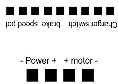
FIGURE 1: Speed controller module connections.
In Part 5, I wrote about recycling microwave oven transformers, which you can also use as a great source of core material and bobbins for mains and output transformers. If you are going to experiment with winding your own transformers, you will need a coil-winding machine, which is available commercially for thousands of dollars, or you can make your own for a small cost.
A coil-winding machine can be as simple or complex as you like. Commercial ones have rotational motors and also feed motors to ensure layers are wound uniformly. Many have the capability to wind more than one bobbin at a time. I now make all my own transformers, and find that all you need is a winder (described here), the materials (you can recycle core material and bobbins), and a bit of practice and patience.

PHOTO 1: Low-cost electric scooter sold on eBay.
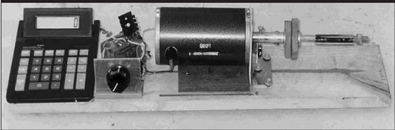
PHOTO 2: Completed coil winder.
My coil winder is a simple one made from an electric scooter, commonly sold on eBay for around $25 US (Photo 1). The final completed coil winder is shown in Photo 2.
This is a small variant of the original, battery-powered winder.
This one has a small mains DC supply, so that I do not need to charge batteries.
CONSTRUCTION
I constructed the coil winder on a 24” × 12 ” length of pine with four rubber feet on the bottom for non-slip purposes.
This makes it a portable and convenient desktop item to use. The winder consists of the base, a motor, battery, controller from a scooter, a calculator, and some other simple parts.
The e-scooter, which is the main source of parts for the project (Photo 3), contains a nice DC motor, a DC speed controller (Photo 4), and two 12V re chargeable batteries and charger. I easily removed these from the e-scooter with simple hand tools.
MOTOR SHAFT ADAPTER
The first task is to cut the head of the 6 × ½ ” bolt to leave a threaded section for the bobbin clamp. Next make an adapter from a length of 3” × 1” aluminum rod to go between the motor shaft and the threaded section of the bolt (Photo 5). The best way to do this is to drill a small pilot hole through the 3” length of the aluminum rod with a ¹/8” diameter drill. This is best done in a drill press or with a lathe. Make sure you secure the rod in a machine vise and center punch the rod before drilling.
Next drill a clearance hole for the motor shaft all the way through the adapter, followed by a clearance hole for the ³/4 ” bolt shank, but this time only 1.5” deep (half the adapter length). Dry fit the adapter to the motor shaft and bobbin clamp bolt. If all is well, apply Loctite adhesive to join the adapter to the motor shaft and the bolt. When the Loctite adhesive has cured, place the completed shaft in a machine vise and drill two 1/8” holes through the adapter to insert locking bolts at the motor and the clamp bolt end. A close-up view is shown in Photo 6.
Make sure that you leave a full length bolt on the motor end. This is used to pulse the turns counter microswitch. You may choose to cut off the locking bolt at the bobbin clamp bolt so that it does not protrude. Use adhesive on the locking bolts as well.
Photo 7 shows a completed winding on the drive shaft, clamped between the wooden end cheeks, washers, and locking nut.
MOUNTING THE HARDWARE
You can mount the winder motor assembly on an aluminum angle bracket fabricated to suit the motor used. Photo 5 shows the bracket I used along with the motor supported on a scrap piece of timber to allow a larger diameter bobbin to be wound. The distance from the baseboard to the center of my motor shaft is approximately 3”. This allows a winding of about 5 ” in diameter. A winding this size is good for around a 1kW transformer.
Another aluminum bracket is required to hold the speed control pot.
And another small angle bracket is used to hold the turns counter micro switch, which is positioned so that each time the motor shaft rotates, the locking bolt closes the micro-switch's normally-open contacts.
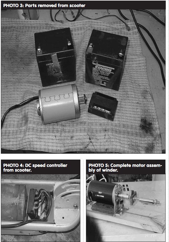
PHOTO 3: Parts removed from scooter
PHOTO 4: DC speed controller from scooter.
PHOTO 5: Complete motor assembly of winder.
Now you need to fabricate two timber bobbin cheek clamps (shown in the Photo 5 close-up) from pieces of ½” thick timber or plywood 2” × 3”, and to drill a 5/8”centered hole in these pieces of timber. The easiest method to find the center is to draw two lines connecting the opposite corners. The point where these lines meet is the center of the piece of timber.
Use a selection of 5/8”diameter tubing as a spacer to handle different width windings and bobbins. Normally the bobbin sits between the two pieces of timber as in Photo 7.
WIRING AND ELECTRONICS
The electronics package is simple. I re-used the original scooter motor speed controller, as well as a $5 calculator as the turns counter. The scooter speed controller is a PWM type rated at about 10A. This is more than ample to control the coil winder.
I replaced the original throttle on the scooter with a conventional linear pot.
I measured the throttle on my unit and found that it was a 10k pot. My original winder was powered by the two 12V batteries supplied with the scooter.
These are also charged with the provided wall-type charger.
For safety's sake, this is a good method to power your winder. I was a little more adventurous at a later stage and fabricated a simple 24V mains operated power supply in stead. The pinout connections for the speed controller are marked on each controller. Figure 1 shows the markings on the unit I purchased.
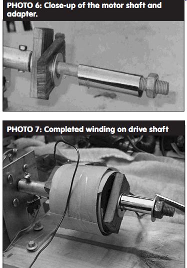
PHOTO 6: Close-up of the motor shaft and adapter.
PHOTO 7: Completed winding on drive shaft
THE TURNS COUNTER
As mentioned, I used a low-cost $5 calculator as the turns counter (Photo 8). The microswitch contacts are simply wired in parallel with the equal (=) key on the calculator keypad.
In the calculator that I purchased, plastic buttons contacted a membrane type switch under the
keypad. The membrane switch is fabricated using a pattern printed on Mylar film. The conductive pattern in this case appears to be similar to Aquadag, a carbon-based material. Connection was simply made by stripping back about ½” of solid drawn copper wire and affixing it using some clear packing tape (Photo 9). (I built this coil winder about two years ago and only recently took the close-up photo of the connection for publication. Even after two years there is little evidence of oxidation on the contact wires.) To start the winding cycle, press 1+. Each time the microswitch contact closes, it effectively presses the = key on the calculator, adding one to the count.
The calculator is capable of keeping up with the fastest rotational speed of the motor. This counter also works if you are pulling down an old transformer and need to count the turns to work out the core turns per volt (TPV).
Another method of using the calculator counter is to work out the volts per turn, by simply dividing 1 by the core TPV. For example, a 5TPV core results in 0.2V per turn. If you are winding a power transformer, you can simply enter the volts per turn into the calculator, followed by the + key. Every turn that is added displays the winding voltage.
For example, 100 turns would add 0.2V to the total 100 times, displaying 20V. The calculator that I purchased was solar powered, which saves the drama of changing batteries. I mounted the calculator to the base board with double-sided tape.
-------------------
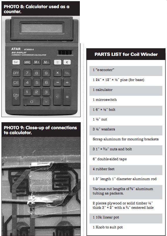
PHOTO 8: Calculator used as a counter.
PHOTO 9: Close-up of connections to calculator.
--------------
PARTS LIST for Coil Winder
1 "e-scooter"
1 24 " × 12 " × ½ " pine (for base)
1 calculator
1 microswitch
1 6 " × ½ " bolt
1 ½ " nut 3 ½ " washers
Scrap aluminum for mounting brackets
3 1 " × ³/16 " nuts and bolt
6" double-sided tape
4 rubber feet
1 3" length 1" diameter aluminum rod
Various cut lengths of 5/8" aluminum tubing as packers.
2 pieces plywood or solid timber ½"thick 3" × 2" with a 3/4" centered hole
1 10k linear pot 1 Knob to suit pot
--------
[The discussion above is adapted from an article, Jul 2005, outlined in xyz ]
Also see: