By Frank Simonsen
Build this neat safety device to connect the audio output of your computer with vacuum tube equipment.
I recently came across some very useful extensive assortment of audio software, but of particular note is …
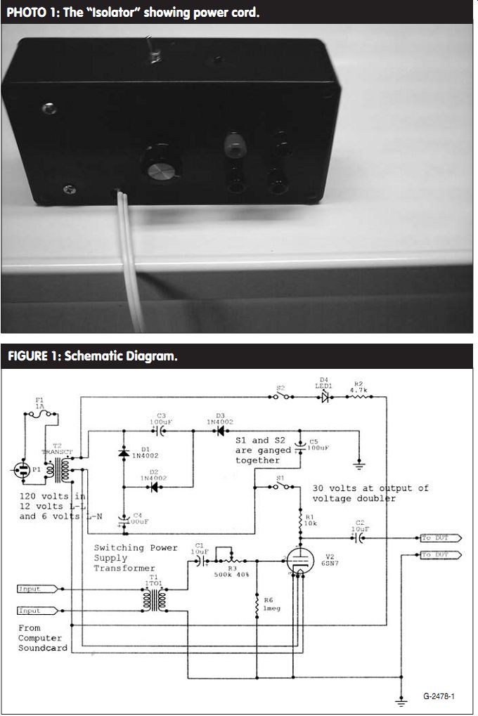
PHOTO 1: The "Isolator" showing power cord.
FIGURE 1: Schematic Diagram.

FIGURE 2: 1.25MHz sweep.
FIGURE 3: 125kHz sweep.
FIGURE 4: 1kHz sine wave before symmetry adjustment.
FIGURE 5: 1kHz sine wave after symmetry adjustment. Drive should be turned down on signal generator for cleaner waveform.
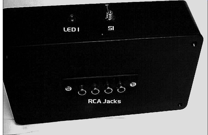
PHOTO 3: Back of device showing RCA jack input.
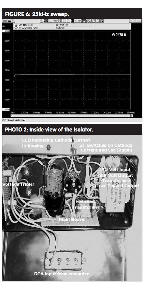
FIGURE 6: 25kHz sweep.
PHOTO 2: Inside view of the Isolator.
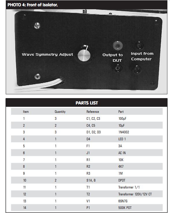
PHOTO 4: Front of Isolator.
PARTS LIST
I downloaded and purchased this soft ware and installed it on my desktop computer; the price is very reason able. It allows you to generate sine, square, triangular, sawtooth, impulse, white noise, and pink noise, and can out put in mono or stereo and up to 16 different test tones on each channel. You can set each frequency independently and sweep them in a linear or log fashion.
You can set the output level in dB, and the frequency goes up to 20kHz.
The output of the sound card is low impedance and solid-state. I remember an unfortunate experience in which I was conducting tests on a piece of tube gear with a solid-state signal generator and inevitably the output transistor was fried. Luckily, it was an easy-to-obtain 2N3903, and I quickly replaced it. I wouldn't want to have this experience with an expensive sound card or an even more expensive laptop computer.
DESIGN GOALS AND CIRCUIT OPERATION
I needed to design an interface device with completely isolated input and output. I thought about using solid-state devices, but I figured that the electrical fragility of the devices precluded their use in this project.
I settled on the 6SN7 because it is easy to obtain and it is a triode, which was fine because I don't need large amounts of gain. The tube is rugged and can work on a low voltage such as 30V. I originally intended to power the device with batteries, but I needed to put it in a small case. The 600mA that the heater requires is not conducive to small batteries, so I settled on a line-powered device (Photo 1).
I wished to isolate the electronics from the line, so I settled on a 12V center-tapped transformer to power both the heater and the voltage tripler, which supplies the plate supply. The power for the LED also comes from the transformer. I sup plied the heater from one side of the transformer output and the tripler from the other.
The LED is supplied by the full 12V. You could use a 6V transformer here, but you would need to change the limiting resistor for the LED to a smaller value. I just used a 12V transformer, which I had in my parts box.
The circuit (Fig. 1) is a very conventional common cathode circuit and the grid is biased at 0V through a 1M ohm resistor. The voltage gain is about
5. The plate resistor is 10k ohm and the output signal is taken out through a 10µF electrolytic capacitor that should be voltage rated as high as possible, at least 50V. The output impedance is less than 10k ohm
The input circuit is isolated through a 1 to 1 ratio switching power supply transformer. The input impedance of the device I used is about 250 ohm at 1kHz.
With one side grounded, the other side is attached to another 10µF electrolytic capacitor. The signal is taken through the capacitor and a 500k ohm potentiometer, which is used as an input waveform symmetry adjustment. With careful adjustment of this control and the level control of the NCH program, you should obtain an excellent output waveform.
Apply the heater current as soon as you plug the unit in. This gives the heater time to warm up before the plate voltage is applied. The LED power is applied at the same time as the plate voltage, indicating when the plate sup ply is on. The 6V RMS voltage is applied to the tripler, and each capacitor charges up to its peak value. The tripled voltage is around 25V DC. My RMS voltage was a little higher than 6V, so the tripler put out about 30V. The difference is caused by the loading on the power transformer. My transformer was fairly lightly loaded, even while supplying the heater cur rent of 600mA, so the output voltage is a little higher than rated.
TESTING AND DEVICE PERFORMANCE
I did some frequency response testing on this circuit. From the measurement graphs (Figs. 2-6), you will notice that the response is poor at the extreme end of the audio spectrum (such as below 30Hz) but is flat up to 25kHz.
The response up to 125kHz is not bad, dropping only about 5dB in 125kHz.
The response from low audio to 800kHz drops about 27dB. This shows that the device is best used in audio testing.
The graphs also show the difference that adjusting the waveform symmetry control makes on a sine wave.
CONSTRUCTION
I constructed the two main circuits on perfboard. I attached the tube socket to the board with the wires that were used to make connections to the actual pins and some hot melt glue. I also glued the boards in place to the inside of the box with hot melt glue (Photo 2). One of the advantages of using hot-melt glue is that you can cut it out if you need to modify. The interconnecting wires were neatly held in place with a bit of hot melt glue. I attached the audio power transformer to the box with ma chine screws. I replaced the input and output connections with "banana" type jack connectors.
I designated the balanced input with two terminals of the same color and the unbalanced output connectors with red and black. The four RCA type connectors of which I used only one were mounted on the rear of the project box (Photo 3). The whole project is housed in a blue project box available at your local electronics store. The 110V cord comes into the box through a hole drilled in the side (Photo 4). Take precautions to tie an Under writers knot to make sure it doesn't slip out when tugged on from outside the box. Work on the unit only when it is unplugged. Keep in mind that the heater current is on immediately when you plug the unit in.
Frank Simonsen is a certified electronics technician working in industrial electronics. He has been interested in audio electronics and particularly tube electronics for many years. He is also a ham radio operator and a collector of antique radios.
SOURCES
All of the parts except the tube and socket should be available from your local electronics store or Digi-Key. You can purchase the tube and socket from Antique Electronic Supply in Tempe, Ariz.
--------
[The discussion above is adapted from an article, Jul 2005, outlined in xyz ]
Also see: