Speakers--The Wedgehorn
--------
By Bill Fitzmaurice
After a number of requests to design a floor "wedge" style live sound stage monitor with higher output capability than his previous designs, this designer built a bigger---and better---monitor.
Monitors suffer more from dispersion issues than perhaps any other speaker, as the distance from the monitor to the listener is usually about 6'. Even a speaker with a reasonably wide 30° -6dB off-axis response has a very narrow listening zone at such short range, and a performer who moves even a foot to either side of his monitor's "sweet spot" can find him self unable to hear it. So when I started to design this box, my primary goal was a super-wide dispersion angle.
Another requirement was high out put, but I wanted to keep the size of the box reasonable, and decided on a short straight horn that would limit the fc to 200Hz or so; but a properly tuned reflex rear chamber could give a response bump at 100Hz for adequate response within the desired passband.
Wide dispersion of the high frequencies critical for intelligibility on stage could be achieved with cross-firing tweeters. And by vertically arraying tweeter pairs, I could produce high sensitivity and a narrow HF vertical dispersion angle. A straight horn would not allow the tight horizontal packing of the tweeter arrays required to minimize combing and keep response flat, but in this application high fidelity reproduction would not be a concern.
The resulting Wedgehorn monitor (Photo 1) has an average sensitivity of 98dB/1W/1m from 100Hz to 12.5kHz.
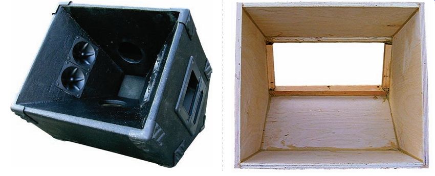
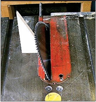
PHOTO 1: The Wedgehorn.
PHOTO 2: Using a cutoff to set the blade angle.
PHOTO 3: The assembled outer shell.
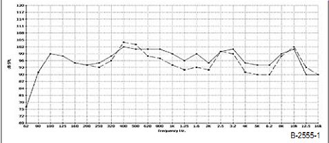
FIGURE 1: On-axis and 45° off-axis response.
This is fairly average for a wedge monitor of this size 16 x 16 x 14”. However the 45-degree off-axis response never drops by more than 6 dB, and in fact averages an exceptional -3db. There are even a few frequencies where off axis sensitivity is higher than on axis. Even at a range of 6’ the sweet spot of this monitor is huge _Fig 1.
The woofer I used is one developed for line array use, the Eminence LA6-MB chose it for its __(z fs ___7 power handling and __d" sensitivity
A rare combination in a ____ driver_
normally you might need to use an eight to get these specs_
& or tweeters ) used four generic piezos
similar to the old #43_Motorola +3.____
Widely available for about a dollar apiece_
!N alternative woofer is the Dayton, Parts express ____
___ _ this is rated at __7
Which should be quite adequate for lounge and other low to medium level acts
And is definitely a bargain at about $16.
Construction
The construction material is ½” plywood, but spruce or pine will do.
But Baltic birch is much easier to work with and finishes with minimal sanding. It also doesn’t add too much to the expense, as you can build two 7edge horns from a single __ s __ sheet_ !ll joints are secured with _ò_ drywall screws piloted and countersunk and polyurethane base construction adhesive
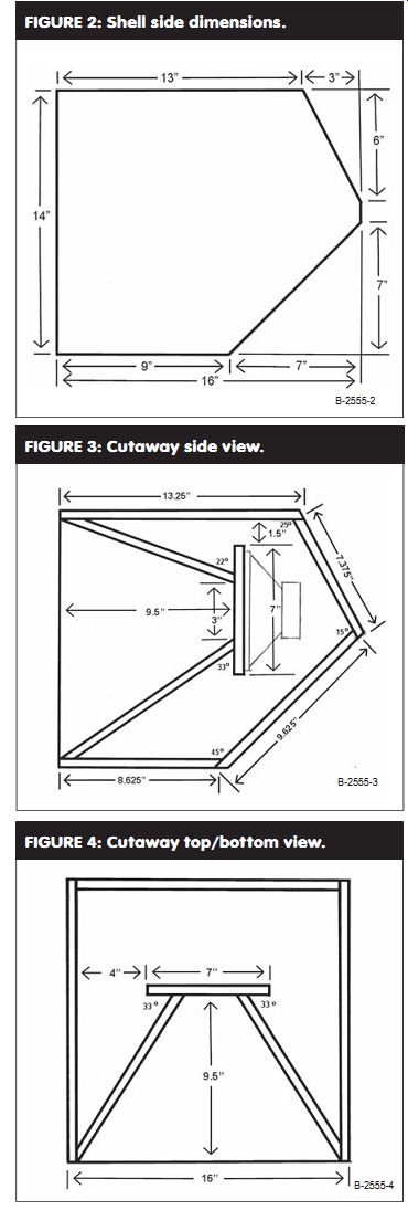
Fig 2 shell side dimensions
Fig. 3 cutaway side view
Fig. 4 cutaway top bottom view
Which expands as it cures to fill gaps_ you start constructing by cutting out the outer shell sides as shown in fig 2 have the triangular cutoffs_ /n the sides draw the joints with the intersecting parts and also the locations of the internal horn pieces as per fig 3. This will serve as a guide in assembling the horn later on. Fig 3 also shows many of the angles to cut those parts for proper fit, as does Fig. 4.
----------- 4
Cut out the shell top, bottom, and two rear pieces per Fig. 3. Double check the dimensions by measuring the layout on the sides, as variations in material thickness may affect the actual size. The top, bottom, and larger rear pieces are 15" wide; the smaller rear piece, removable for driver access, is 14.875" wide. Setting the table saw blade angle off vertical for the angled cuts is very easy using ...
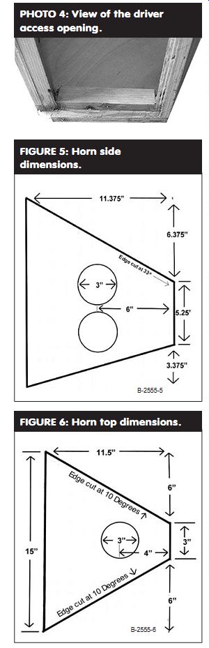
PHOTO 4: View of the driver access opening.
FIGURE 5: Horn side dimensions. FIGURE 6: Horn top dimensions.
... the saved triangular cutoffs as guides (Photo 2). Assemble this box by first attaching the top, bottom, and larger rear panel to one side, then attaching the remaining side to the assembly.
Frame the opening where the driver access panel will attach (Photos 3 and 4); you can use cutoffs from the top and bottom that are already cut at the correct angles. On the top draw the locations where the internal horn parts will go, as per Fig. 4.
Cut out the remaining parts, including a 7" × 7" baffle. Check Figs . 3-7 for sizing and the angles of the various cuts. You need to make two horn sides (Fig. 5, which you'll note is shown upside down relative to the side view of Fig. 3), mirror imaged with respect to the 33° angle cut where they attach to the baffle.
Before cutting each part use the layouts drawn on the exterior of the box as guides to assembling the various parts.
When you cut the edges of the horn top and bottom at the indicated angles, the wider face of each part will be on the interior of the horn.
Cut 3" diameter holes in the parts for the ports and tweeters, preferably with a hole saw.
(Note that I did not cut these holes on the prototype until after assembling the box, because I didn't know until then precisely where they would end up.
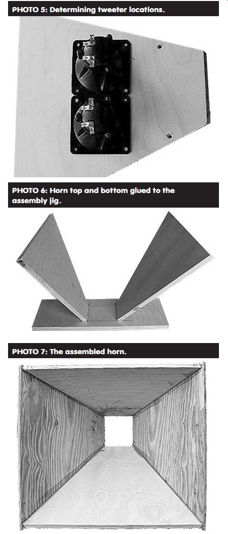
PHOTO 5: Determining tweeter locations.
PHOTO 6: Horn top and bottom glued to the assembly jig.
PHOTO 7: The assembled horn.
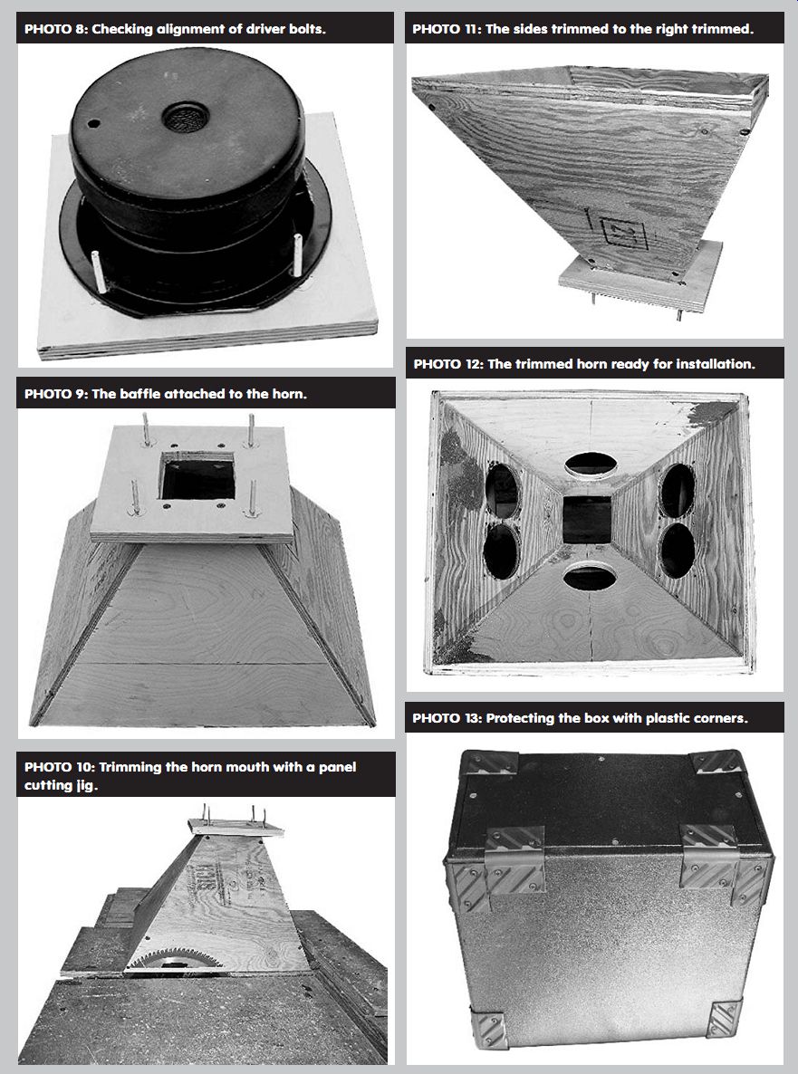
PHOTO 9: The baffle attached to the horn.
PHOTO 8: Checking alignment of driver bolts.
PHOTO 10: Trimming the horn mouth with a panel cutting jig.
PHOTO 11: The sides trimmed to the right trimmed.
PHOTO 13: Protecting the box with plastic corners.
PHOTO 12: The trimmed horn ready for installation.
Cutting them prior to assembling the box is much easier.) In the case of the tweeter holes, first draw a centerline on each horn side 6" from the baffle end. Place a pair of tweeters with their frames touching centered on this line, with the distance from their frames to the nearest edge equalized to deter mine the actual centers of the mounting holes, as in Photo 5.
ASSEMBLY
To assemble the horn, start with a piece of scrap plywood, onto which you draw a 3" × 3" square representing the horn throat. Using a small amount of hot melt glue, attach the horn top and bottom pieces to this jig (Photo 6). With the top and bottom secured, it's an easy job to then attach the horn sides and remove the finished assembly from the jig (Photo 7).
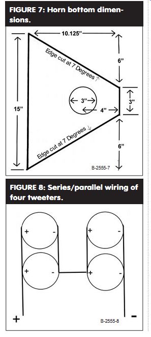
FIGURE 7: Horn bottom dimensions.
FIGURE 8: Series/parallel wiring of four tweeters.
Now cut a 3" × 3" hole in the middle of the baffle. Use the driver to deter mine the mounting bolt hole locations, drill the holes and insert ³/16" T-nuts, and then trial-fit the driver to be sure all is right (Photo 8). (For testing purposes I mounted the T-nuts on the driver side of the baffle, with the bolts coming through the baffle; insert the T nuts from the opposite side of the baffle using 1" long attaching bolts.) Put the driver aside and attach the baffle to the horn assembly (Photo 9).
Now you can trim the mouth of the horn to fit into the shell, a very simple process with a table saw and panel cutting jig (Photo 10). The horn sits atop the jig, mouth down. The jig slides across the table saw top, and the blade set at vertical trims the horn sides to the correct angle (Photo 11). Don't try to cut the horn to its finished size in one pass. Instead, trim each of the four edges a little at a time, gradually reducing the size of the horn mouth until it just fits into the shell. Then attach it using plenty of adhesive to fill any gaps.
Fill all screw heads and defects in the project (I use automobile Bondo, which doesn't shrink and sets up fast), and when the glue and filler are set, sand everything smooth. Also put a ½" radius chamfer on the exterior edges with either a router or sander, and round over the joints on the rear of the box (Photo 12). Temporarily screw the access panel into place and use a sander to round over where it meets the top. If you plan on using either handles or jack hardware that require cutting holes in the box, do it now. Be sure that you don't put a recessed handle where it will smack into the tweeters.
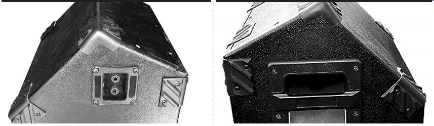
PHOTO 15: An insert handle for easy hauling.
PHOTO 14: Dual phone jacks for daisy-chaining.
FINISHING TOUCHES
The next step is applying a finish. Carpet is an attractive and durable option, but it isn't easy to apply and is relatively expensive. I tried a product called DuraTex for the first time with this project (available from Acry-Tech at 800-771-6001) and am very pleased with the result. Intended as a speaker finish, this water-based urethane acrylic goes on with a standard paint roller, drying quickly with a lightly textured finish that's very durable and easily recoated if you ding it up. It doesn't cost much more than paint, coverage is quite good, and you can finish a cabinet of this size in about 15 minutes exclusive of drying time. Using a small trim roller, you can reach inside the box to cover those areas visible through the ports.
After the finish has cured, start applying protective corners. I like to use large plastic corners that are not only cheap but also can be trimmed where you don't want to have them wrap over an edge, as in Photo 13. They are also flexible enough to use over the corner formed by the upper and lower back pieces even though the angle formed is less than 90° (Photo 14).
Line the box as much as possible with either polyester batting or acoustic foam to prevent internal reflections.
Then install your drivers, starting with the tweeters. You may wire all the tweeters in parallel for maximum sensitivity, or series/parallel wire for higher power handling with 3dB less sensitivity (Fig. 8). Either way, keep the tweeters and woofer in phase.
Before mounting the woofer, install some type of protective grille on the baffle; I used ¼" thick air conditioner filter foam on mine. Also double-gasket the woofer to prevent cone-slap against the baffle. Install jacks and handles, line the access cover with poly or foam and install the cover. Last, complete the installation of protective corners wherever you can (Photo 15).
The dual angles of the box rear allow you to place it on the floor in a shallow angle as shown in Photo 1, or at a steep angle as shown in Photo 16. Remember that while the nominal rating of the woofer is 150W, the box is tuned to 100Hz, so you should use either a high pass filter set at 100Hz or roll off the EQ of the monitor send below 100Hz to keep out potentially destructive bass frequencies. Most important, unless you have separate EQs, sends, and amplifiers for each monitor in your system, they must all be identical. Otherwise, you won't be able to get them to all sound the same and notching out feedback will be almost an impossibility. Luckily, you can construct even a stable of six Wedgehorns for about $400 using the Dayton woofer, so having all identical monitors is an afford able luxury.
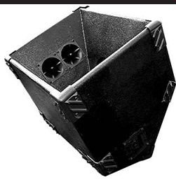
PHOTO 16: Steep angle placement for close-in listening.
--------
[The discussion above is adapted from an article, Jul 2005, outlined in xyz ]
Also see: