Build this high-quality tube preamp and you'll hear the difference in your audio setup.
I designed the tube preamplifier de scribed here with the following requirements:
• Operate the tubes reasonably near the points where the manufacturer specified the tube parameters; spec points for the 6922 are 12mA Ip and 15mA Ip at 90 and 200V B+. This ensures that rp and gm are stable over the normal operating range of the circuit.
• Select plate loads and operating points so that the load line intercepts near equally spaced grid lines at the operating point.
• A passive and accurate RIAA compensation network in the phono stage.
• A separate power-supply box and a power-supply topology that simulates a separate supply for each channel.
• Input level controls for each source so that the volume levels do not change between sources.
• No feedback used in the design.
PHONO STAGE
In Fig. 1 the power-supply voltage divider/filter supplies 118V DC B+ to V1A. The 8.7kO plate load resistor, R2, and the 150 Ohm self bias resistor, R3, set the operating point at Ep = 61V DC and Ip = 6.6mA. This is close enough to the spec point to set gm to 9900µS (microsiemens) and rp to 3.33k-O, resulting in an output impedance of 2400 Ohm and a raw gain of 23.8.
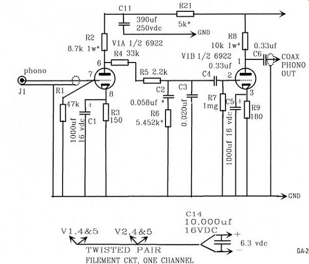
FIGURE 1: Phono stage schematic.
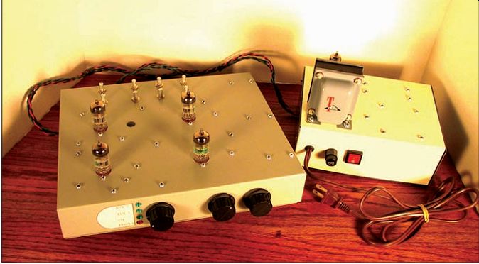
PHOTO 1: Front view, main chassis, and power supply.
The equivalent noise resistance is 200-O at a gm of 12500µS. The design point of 9900µS should keep the equivalent noise resistance below 300-O, resulting in a quiet phono stage. R1, a 47k-O resistor, provides the nominal load for a moving-magnet cartridge.
The phono input is a coaxial cable be tween the phono-in jack and the grid of V1A and connected at the grid ground.
RIAA compensation is provided by the RC network, R4, R5, R6, R7, C2, C3, and C4. Neglecting the frequency effects of the compensation network, the series resistance reduces the first stage gain to 22.8 at the grid of V1B. The RIAA compensation further reduces the gain by a factor of ten at 1kHz, -20dB. C1 bypasses R3 to a frequency well below 10Hz. V1B has a B+ of 151V DC. The 10kO plate load, R8, and the 180-O cathode resistor R9, bypassed by C5, set the operating point at a gm of 10,000µS and an rp of 3275-O. The output impedance is 2467-O with a resulting gain of 24.7. The overall gain of the phono stage at 1kHz is 35dB. The output of the phono stage is coupled via C6 to a 250k-O level control, R13, then to the selector switch.
LINE STAGE
V2A, the first line stage amplifier (Fig. 2), is identical to V1B except for a small change in the cathode self-bias resistor.
The small signal parameters as well as the gain are the same. The input to V2A is via a coaxial cable from the selector switch. The cable shield is grounded at the tube end only.
The output of V2A is coupled through C7, then to the channel volume control using a twisted pair. The wiper of the volume control goes to C9 and then to the grid of cathode follower V2B, which is set to operate with a 1-k of 7.9mA and an output impedance of about 120-O. The 7.9mA 1k ensures a stable value of rp and low output impedance sufficient to drive loads down to several kilohms without strain. The output is coupled through a 2.2µF capacitor, C10. R20 provides a bleed path when the unit is operated without a load.
INPUT, LEVEL CONTROLS, AND SELECTOR SWITCH
All RCA jacks are of the insulated variety (Fig. 1). The phono input, J1, connects directly to the grid of V1A through a coaxial cable; the cable shield goes to the shield side of the RCA jack and to the cathode ground of V1A. The CD and aux inputs are connected to their respective level controls, R11, R12, and R13, via twisted pairs. The low sides of R11, R12, and R13 are connected together by a ground bus (Fig. 4). The lead from the jack shields goes to the ground bus next to the corresponding level control, and the lead from the center conductor goes to the high side of the level control.
A twisted pair joins each level control center tap to the corresponding selector switch position; the ground side of each twisted pair is connected to the ground bus next to the level control only-they are not carried through the selector switch-this includes the center tap of the phono level control R10 (Fig. 2). A grounding lead connects to each ground bus between R11 and R12 and to the corresponding cathode ground of V2A. The phono output from V1B goes to the phono level control, R10, via a coaxial cable, the shield is connected to the cathode ground of V1B and the low side of the level control. The ground bus between V1 and V2 will provide a single path ground for the phono signal. The left and right channel outputs of the selector switch are connected via coaxial cable to the grids of the left and right channel V2A; the shields are connected to the cathode grounds of V2A (Fig. 4).
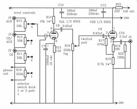
FIGURE 2: Line stage schematic.
POWER SUPPLY AND DC DISTRIBUTION
The power supply (Fig. 3) uses a 6X4 full-wave vacuum tube rectifier to develop the plate voltage for the pre amplifier. R1, 47-O, combined with the DC resistance of the secondary, pre vents hot switching and limits peak currents that could occur during the initial charging of the 390µF capacitance of C1. R2 and C2 provides additional filtering and reduces the DC voltage to 158V DC. R3 and R4 divide the 158V DC to 16V DC and provide a positive bias to the filament supply, preventing filament to cathode leakage in the low-level circuits. A 6' long twisted pair connects the 158V DC to the preamplifier chassis, where it splits into separate left and right channel supplies. R22, 220-O, C12 and C13 give channel isolation and filtering for V1B and V2. R21, 5k-O and C11 reduce the supply voltage to 118V DC for V1A and provide filtering and isolation from the higher level circuits.
A full-wave bridge, D1, rectifies the 6.3V AC. R1 limits the output cur rent of the rectifier and sets the DC to 6.3V DC as measured across the tube filaments. C3, 10,000µF, is for the initial filtering.
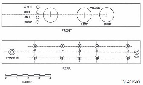
FIGURE 3: Power supply schematic.
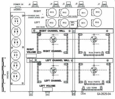
FIGURE 4: Main chassis parts placement, bottom view.
The filament line is then split into two paths, one for each channel. C4 and C5 provide filtering for each channel. Two 6', 20 gauge twisted pairs carry the filament current to the preamplifier, where each channel receives an additional 10,000µF filtering capacitor, C14.
Control and protection is provided by the S1 on-off switch and F1, a ¾A fuse.
C6, 0.033µF 600V DC capacitor, filters conducted RFI from the mains.
The transformer used is a Triad R- 22A, which is no longer produced by Triad, but can be found at auctions or swap meets or for a hefty price at onlinecomponents.com. The original de sign included a 155V DC source. Hammond has a 369BX transformer that supplies 150-0-150V AC at 75mA and 6.3V AC at 2A that will work fine with a separate 6.3V AC transformer for the rectifier filament. If you use the 369BX, change power supply R2 to a 110-O 1W resistor. Change the left and right channel R22 to 110-O on the main chassis filter assembly.
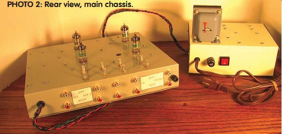
PHOTO 2: Rear view, main chassis.
RESULTS Hum and noise with the inputs open:
Line stages 90dB below 2.5V RMS output
Phono 80dB below 5mV RMS input
RIAA equalization: Within 0.25dB 20Hz to 20kHz
Frequency response, line stage:
-0.5dB at 10Hz -1.0dB at 500kHz
Distortion, volume controls at maximum output level controlled by signal level
Distortion products predominantly second harmonic (Photo 3)
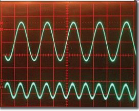
PHOTO 3: Distortion products, 1V RMS output.
Upper trace: 1kHz preamplifier output.
Lower trace: 0.23% distortion component, primarily second harmonic.
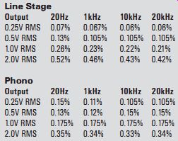
I measured the distortion with a Sound Technology 1700A Distortion Measurement System. Residual distortion of the unit was 0.002% or less at all test frequencies. Of note is the reduction of distortion at levels above 0.5V RMS in the phono position. This is due to the cancellation of even harmonic products generated in V1B and V2A. It actually occurs at the lower levels also, but the effect is overpowered by the boost of low-frequency noise due to the RIAA compensation.
MAIN CHASSIS CONSTRUCTION
I started by covering the front top and rear sides of the chassis with masking tape to provide a surface to transfer drill locations for parts mounting and protection of the finish. Use Photo 4, Figs. 4-7, and actual parts to determine locations. Note that the arrow on the tube sockets (Fig. 4) represents the gap be tween pins 1 and 9. At this time I built up the walls (Fig. 6) to ensure that the mounting holes for the selector switch and the right volume controls and the corresponding front panel bushing mounting holes were aligned.
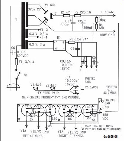
FIGURE 5: Front and rear panel layout.
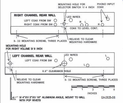
FIGURE 6: Right and left channel walls detail.
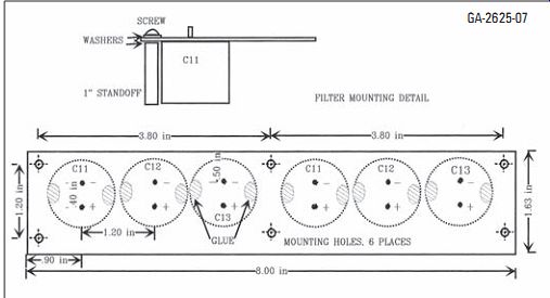
FIGURE 7: Filter capacitors mounting detail.
Cut a 1 3/8 " by 8" strip of perfboard for filter capacitor mounting. Locate the six mounting holes for the 6-32 screws as shown in Fig. 7. Drill the mounting holes and transfer the locations to the chassis top. Locate the holes for the capacitor terminals per Fig. 7 and drill the holes out to ¹/16"; note that all hole locations will line up with the board perforations.
Following is a list of drill sizes for the various chassis holes:
All mounting screws are 6-32, use 1/8" drill Front panel
Bushings and left volume control, 3/8" drill.
LEDs, ³/16" drill Rear panel
J1 through J5, 3/8" drill
Power in grommet, 5/16" drill
Phono ground, ³/32" drill Top
Level controls, R10 through
R13, 9/32" drill tube sockets, ¾" chassis punch
WALLS
The mounting holes and switch shaft clearance hole are marked. Use a ?" drill for the 6-32 mounting screws and a 5/16" drill for the remainder. Transfer the mounting screw locations to the chassis top.
After drilling and punching all of the holes, mount the chassis hardware using Photo 4 and Fig. 4 as guides. Scrape the paint off the inside surface at the phono ground. Do not mount the walls or the RIAA terminal strips at this time. Note that I used turret sockets, but much of the wiring is similar.
Start the wiring by twisting together two 6' lengths of 22-gauge stranded wire-red and black or your favorite colors. Use about 2' for the filament wiring and the rest for the input jacks to level controls and level controls to selector switch and volume control wiring. I generally start by wiring the filaments. After that, proceed to the input wiring.
Strip two pieces of solid 20 gauge for the ground buses on R11, 12, and 13, and install as shown. Next, wire the left high-level inputs to the corresponding left level controls. Then do the same for the right high-level inputs.
Then, prepare the coax cables for the phono inputs, phono outputs to the phono level control, phono level control to selector switch, and the selector switch to V2 pin 7, both channels. Cut so that there is at least 1½" of slack on each lead. The phono input will require shield ground leads at both ends, while the remainder will require ground leads only at one end.
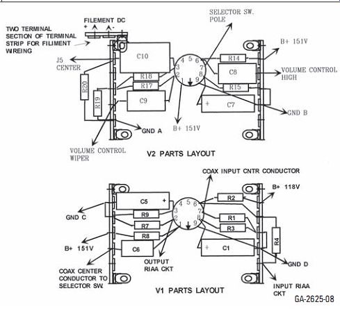
FIGURE 8: V1 and V2 parts layout.
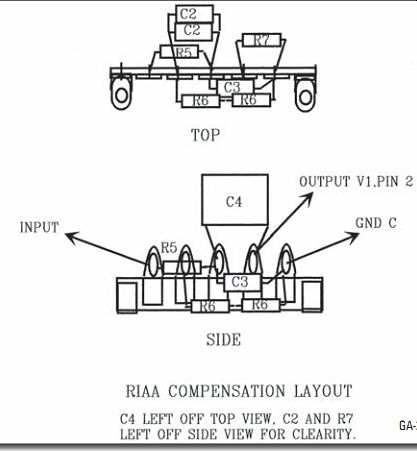
FIGURE 9: RIAA assembly parts layout.
Prep the ends by removing about 3/8" of the outer cover. For the leaded ends, open up the braid, twist it, and tine the braid.
Remove the braid on the ends without ground leads. Strip about 1/4" of the inner insulator and tin the center conductor.
Attach and solder 2" of 22-gauge stranded wire to the ends requiring ground leads and cover all ends with shrink sleeving, leaving the last ³/16" of the center conductor and insulator exposed.
Connect the phono input coaxes to J1 left and right. Connect the coax to the high and low sides of R10, both channels.
Next, pre-wire the selector switch (see Figs. 2, 10, 11, and Photo 4). The right channel inputs go to deck 2, left side with pole 1 being the output.
The phono coax that connects to the center of R10 goes to position 1. Cut three pieces of the twisted pair about 3" long. Cut the ground side back about ¼", remove about 1/8" of the insulation from the hot lead, and then tin the conductor.
Attach these to positions 2, 3, and 4 of deck 2.
Attach the output coax that goes to the right channel V2 pin 7 to pole 1, using the end without the ground lead.
Repeat for the left channel using deck
1. Cut a foot-long piece of red 22-gauge stranded and connect one end to deck 2, pole 2. This will supply +6.3V DC to the LEDs through the selector switch.
Now you will need four pieces of 24 gauge or so cut in 1' lengths, preferably a different color for each. Attach these to terminals 1, 2, 3, and 4 of deck 2, pole 2 side and to the positive side of the LEDs on the LED terminal strip.
I used a bit of intercom four-conductor ribbon-a broken telephone extension cord or individual wires would serve as well. Mount the right channel wall to the chassis. Feed the leads going to the right and left channels through the appropriate holes and mount the selector switch to the wall. Hook up the switch to level control wipers and ground, and switch position 1 to R10, 2 to R11, 3 to R12, and position 4 to R13. Trim the twisted pairs to length as required.
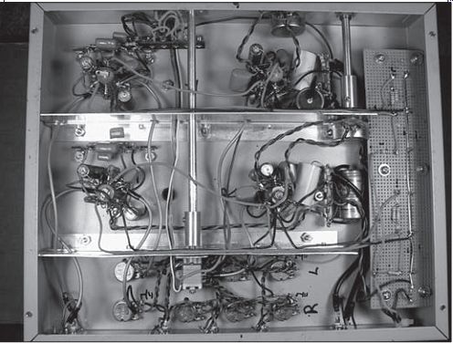
PHOTO 4: Main chassis construction and location detail.
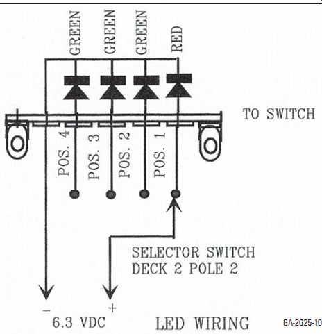
FIGURE 10: LED wiring.
Connect a 6" piece of 22-gauge black stranded to the right ground bus between R11 and R12 and a 10" piece to the left ground bus. Feed the right lead through the hole with the right channel coax from deck 2, pole 1 of the switch, with the left lead going through the left hole. Mount the left channel wall.
Refer to Figs. 1 and 8 for parts location and identification for right channel V1. Connect the phono input and R1 to pin 7 first, then proceed with the rest of the parts as shown in Figs. 2 and 8. Note that R2 consists of two 17.4k-O resistors in parallel, while R8 has two 20kO resistors in parallel. Complete wiring shown in Fig. 8 by hooking up the coax from the high side of R10 to C6 and ground. Connect V1 pin 9 to ground.
Refer to Figs. 1 and 9 to build up the RIAA circuits. Note that C2 consists of a 0.036mF capacitor paralleled with a 0.022mF capacitor and R6 includes a 5.1kO resistor in series with a 360-O resistor. Build a circuit for each channel at the same time to ensure that they are as identical as possible. Mount and connect the right-channel circuit.
Referring to Figs. 2 and 8, build up the circuitry for V2, and connect the coax from the switch first. The center conductor goes to pin 7 and the ground lead to the ground for R15. Connect the right channel ground lead from the ground bus between R11 and R12 to the same ground.
Complete the circuitry as shown in Fig. 8. Note that R14 consists of two 20kO, ½W resistors in parallel and R19 includes two 17.4k-O, ½W resistors in parallel. Using 20-gauge black stranded, construct the ground bus by joining the leads between ground points A, B, C, and D as shown in Fig. 8. The ground from the right channel B+ filters goes to ground A. Using 22-gauge red stranded, connect the +165V DC points listed in Fig. 8 together starting at V2 pin 1, then to the high side of R14 and ending at the high side of R8. The +165V DC from the filter connects to V2, pin 1. Repeat the process for the left channel.
To simplify wiring, connect the LEDs per Fig. 10 prior to installing the RIAA circuits. Connect the -6.3V lead from the LEDs to the negative terminal for the left-channel filaments and the red lead from the switch, pole 2 of deck 2, to the positive terminal. Finish the left-channel wiring.
Refer to Fig. 7 and mount the filter capacitors to the perfboard, applying a drop of glue to opposite sides of the capacitor and push the terminals through the enlarged holes with the negative terminal next to the edge as shown. It takes about 45 minutes for the glue to set. Mount the standoffs as shown in Fig. 7, using two washers on each screw as shown.
Refer to Fig. 4 and scrape the paint free from around the mounting hole that will also be used for the chassis ground.
Prep a 3.5" length of black 22 gauge stranded by soldering a spade lug to one end; this will be the chassis ground lead.
Mount the filter assembly to the chassis with the ground lead lug under the standoff shown in Fig. 4.
Refer to Photo 4 and Fig. 3 to wire the filter assembly. Use a length of solid 20 gauge for the ground bus. Lace the end nearest the rear down through a hole in the perfboard and back up through the next hole to form a circle about ?" or so in diameter. Do the same with the free ends of the resistors. This secures the leads to the board and makes convenient solder lugs.
Note that the 5k-O resistors, R21 for each channel, are two 10kO ½W resistors in parallel. Build up the umbilical power cord with two twisted pairs of 20 gauge stranded-I used black and green for filaments-and one twisted pair of 22 gauge, black and red for B+, about 6' long.
Use 1" lengths of shrink tubing spaced about every foot or tape wraps to maintain the integrity of the cord. Feed one end of the cord through the grommet (see Photo 4 and Fig. 4), cut the filament lines and B+ lines to length and solder in place along with the filament filter capacitors, C14. Mount the capacitors so they rest along the right and left walls and hold in place with a bead of glue.
Connect the left and right power grounds and the left and right +151V DC and +1118V DC lines to complete the main chassis wiring. I ran the power and ground lines along the walls and held them in place with beads of glue. Use a nylon tie around the cord at the grommet for strain relief.
Cut the shaft extensions so that they extend the same length from the front panel as the left volume control shaft.
The coupler for the switch shaft will need a bushing to step the shaft size down to 1/2 " at the switch end. Cut a 3/8" length off a 6-32 standoff.
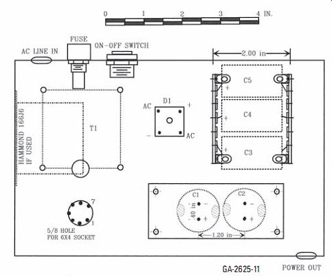
FIGURE 12: Power supply parts layout.
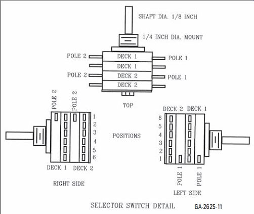
FIGURE 11: Selector switch details.
Drill the threads out with a 1/8" drill, then locate the center of the 3/8" length and drill a 1/8" hole in the wall. This will allow the coupler set screw to engage the switch shaft. Line up the hole in the bushing with the coupler set screw and slide it into the coupler, turn the set screw in a few turns to prevent the bushing from moving, and slide it onto the switch shaft and tighten the set screw. Install the extension shafts and knobs to finish the main chassis.
POWER SUPPLY
The power supply is constructed in a similar manner as the main chassis. Use Photo 5 and Figs. 3 and 12 to determine part location and type. The filter assembly for C1 and C2 is a smaller version of the one in the main chassis. After completing the mechanical assembly, proceed with the wiring by referring to Photo 5 and Fig. 3.
Note that R5, 0.24-O 2W, contains two 0.47-O 1W resistors in parallel. Install only one of these now so that there is 0.47-O in series with the filter capacitors; you may install the second after initial test. Complete the power-supply wiring and install the free end of the umbilical power cord and use a nylon cable tie for a strain relief.
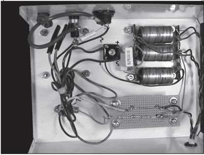
PHOTO 5: Power supply construction and parts location detail.
TESTING
Carefully check for cold or marginal solder joints, especially those with three or more connections. Check for power and ground continuity. Inspect each tube section for plate to power resistance, equal to the plate loads, grid to ground and cathode to ground as well as shorts between elements. If all is well, load the four 6922 tubes into the main chassis (do not install the 6 × 4 rectifier in the power supply).
Monitor the filament voltage at the C3 side of R5 and turn the power supply on. The DC voltage should slowly rise toward 6.3V DC. If the voltage exceeds 6.4V DC, turn the supply off and install a 0.47-O 1W resistor between C3 and C4 and repeat the preceding. A 0.47-O resistor will drop about 0.56V DC in this application and the parallel combination of 0.24-O will drop about 0.24V DC. Use these figures to adjust the output to 6.15 to 6.3V DC. If the initial voltage was low, parallel R5 to adjust the voltage.
I am running mine at 6.18V DC. With the filament voltage set, note which one of the selector switch LEDs is lit, de pending upon the selector switch setting.
Check that each of the four positions is correct. These LEDs also indicate the power-supply on-off function.
Install the 6 × 4 in the power sup ply and turn the power supply on; the voltage at C2 in the supply should rise to around 158V DC. If so, check the 151V DC lines to each channel. They should stabilize near 151V DC and there should be less than 5V DC difference between channels; the same is true for the 118V DC lines. Use the following table to affirm correct operation of each stage. Allow the unit to warm up for five minutes before measurement.
Operating voltages Pin # V1 voltage V2 voltage 1 76.8 151 2 0.0 68.7 3 1.2 70.2 6 61 72.6 7 0.0 0.0 8 1.0 1.1
I took the above voltages on my unit using NOS JAN Philips 6922 tubes; other quality tubes should have similar readings. The readings are power-supply dependent so that if the power supply is running low then the readings will be lower than recorded.
SETTINGS
The following adjustments are made with a signal generator set to 1kHz. The volume controls are set to maximum cw (clockwise) rotation, and the level controls should be initially set to minimum, fully ccw (counterclockwise).
The maximum output for most CD, SACD, and DVD Audio players is 2.8V RMS. If your player differs, use the maximum listed output level as the input.
You can also set the level controls in the system by placing the volume controls in the one o'clock position and adjusting the level controls for a normal listening volume. There are no further specific turn-on or -off procedures required. The power-supply design eliminates turn-on or -off thumps.
HOW DOES IT SOUND?
The first audition was a pleasant surprise. It added several heaping measures of fun to my listening and exceeded my expectations. I have spent much time finding musical content that I had not heard before or at least was not aware of. The preamp presents no indication of strain or intermingling of instruments or voice. A wide and stable soundstage is formed with stable location of instruments in the stage width, depth, and height. The sonic transparency allows you to follow background instruments through passages that are 20 to 40dB or so louder than the background instrument. SACDs, especially the good ones, are presented in a manner that exemplifies the sonic advantages of the format.
For vinyl I use an old but good Supex 900 MC cartridge and a step-up trans former with a cartridge load of 80-O. The vinyl presentation is superb with detail and transparency that puts the fun back into vinyl. Yes, good vinyl does present better than SACD.
Our club had a preamp shoot-out in which this preamp was compared to the following equipment:
Audible Illusions Modules 3 with the John Curl mc board Dynaco (Panor) Pas 4 tube preamp Adcom AP110 Supratek Cortese Audible Illusions-very close. Possibly less dynamics and a small limit on the high-frequency presentation. Note: the John Curl stage takes a bit of work to adjust cartridge loads.
Dynaco-Close. Somewhat noisier and a bit constrained on the high end.
Adcom-No contest. Not in the same league.
Supratek--This unit had a bit of trouble driving long, 15 to 20' cables, possibly due to the transformer output.
The owner did indicate a definite liking of this preamp. aX
Test Equipment Sound Technology 1700A
Distortion Measurement System HP 651B Test Oscillator HP 334A Distortion Analyzer HP 350D Attenuator Set B&K Precision 2830 Digital Voltmeter Hitachi V550B Dual Channel
Oscilloscope, 50MHz.
---p11 *For std. line output, 0.707V or the maximum output of the device being used.
---------------------
PARTS LIST.
Component D Chassis Cover plate Cover plate1 1 Chassis2 Cover plate3 7 Terminal strip 5 Tube socket Tube socket Bushing4 Shaft coupling s Aluminum angle ½ Aluminum rod or thick walled tubing ¼ Standoff Perf board Knob RCA phono jack r RCA phono jack w Glue Screws Nuts Lock washers 6 T-1
Selector switch5 4 On-off switch P Fuse holder Fuse Coax cable6 Hook-up wire7 S RESISTORS (All resistor R1 R2, R19 R3, R15 R4-R5 R6 R7 R8, R14 R9, R18 R10-12 R13 R15 R17 R20 and power supply R3 1 R21 R22 Power supply R1 4 Power supply R2 2
Power supply R4 1
Power supply R5 0
CAPACITORS C1, C5, C7 C2 C3 C4, C6 C8, C9 C10 C11-13 and power supply C1, C2 3
DIODES and RECTIFIERS
Red LED Green LED Full wave bridge rectifier 6 TUBES 6922 Jan Phillips 4 required 6X4 rectifier 1 required
--
Description
12" × 10" × 2" Hammond P-H1441-29 12" × 10" Hammond P-H1431-29
12" × 8" Hammond P-H1434-22 7" × 5" × 2" Hammond P-H14412
7" × 5" Hammond P-H1434-12
5 lug, 0 common, 13 required 9 pin, 4 required 7 pin, 1 required ¼", 2 required solid, 2 required
½" × ¾" × ¹/16", 18" long
¼" OD, 12" long 1" 6-32 threaded, 11 required 6" × 8" Radio Shack 276-1369 3 required, Radio Shack 274-403
red insulated, 5 required
white insulated, 5 required BEACON Plex bond or similar 6-32, ?" long, 70 each 6-32, package of 100
6-32 70 Power transformer, Triad R-22A, 320VCT at 70mA, 6.3V AC at 600mA, 6.3V AC at 3A. See text. Alternatives are: Hammond 369BX, 350VCT at 75mA, 6.3V AC at 2A Hammond 166J6, 6.3V AC at 1A
4 pole 2 decks, enclosed rotary switch.
Power supply, rocker switch Panel mount Radio Shack 270-367 3AG, 1A 6' audio cable
See text
0.5W, 1% metal film unless otherwise specified) 47k-O, 2 required 8.7kO (2 each 17.4k in parallel), 8 required 150-Ohm 4 required
33kO 2 required
2.2kO 2 required
5.432kO (5.1k-O and a 330-Ohm bin series), 2 sets required
1.0MO, 2 required 10kO (2 each 20k in parallel), 8 required 180-O 4 required 50kO screwdriver adjust potentiometer, 16mm 6 required 250kO screwdriver adjust potentiometer, 16mm 2 required 250kO 10% log taper, 2W potentiometer 2 required 470kO 2 required
100kO 5% carbon film 3 required 5kO 5% carbon film, 1W (2 each 10kO in parallel) 4 required 220-O 5% carbon film, 2 required
47O 5% carbon film
220-O 1W metal oxide
12kO 5% carbon film
0.47-O 1W metal oxide 2 required
1000µF 16V DC electrolytic 6 required
0.058µF 3% 400V DC metal polypro (0.036µF and 0.022µF in parallel) 2 sets required
0.020µF 3% 630V DC metal polypro 2 required
0.33µF 5% 400V DC metal polypro 4 required
0.62µF 5% 400V DC metal polypro 4 required 2.2µF 5% 400V DC metal polypro 2 required
390µF 250V DC electrolytic 8 required C14 and power supply C3-5 10,000µF 16V DC electrolytic 5 required 1 required Radio Shack 276-084 3 required Radio Shack 276-085
6A, 200 vpiv


----
1-Walls. 2-Power supply. 3-Power supply. 4-May be salvaged from ¼ in shaft potentiometer. 5-Mouser Electronics 690-C1 D0406N-A. 6-As thin as can be found. 7-Radio Shack is fine
Also see: Adcom GFP-555 Preamp Upgrade
A Tube-Based Power Solid-State Amp