Although devices for passive infrared detection have been in existence for a number of years, it is only relatively recently that they have become readily available to amateur electronics enthusiasts. So also have the special lenses for use with these devices, and quite high performance units can now be produced using what are really very simple circuits comprised of just a handful of components. These devices certainly represent an interesting aspect of electronics and have numerous possible uses including such things as burglar alarms, automatic doors, and automatic lighting.
Basics It would perhaps be as well to start with an explanation of just what is meant by a "passive" infrared detector. This is a device which merely detects infrared radiation produced by a source of some kind, but which will normally be a person. In other words it is a circuit which is designed to detect body heat, and then to operate an alarm generator (or whatever). It differs from active infrared detectors in that they transmit an infrared signal of some kind, and detect anything that interferes with this signal in the appropriate way. In most cases units of the active type transmit a beam of infrared pulses, and a receiver unit picks up these pulses and holds-off an alarm generator while they are received. If someone should break the beam so that the pulses no longer reach the receivers the receiver circuit activates the alarm.
There is a alternative and much less common type of active sensor, and this is the type which transmits a pulsed infrared beam and detects the presence of objects by the infrared signal that they reflect back to a receiver unit mounted alongside the transmitter. However, units of this type generally have very restricted ranges and respond with reasonable sensitivity over only a very restricted area. The broken beam type circuit gives very good range (as much as 100 meters being achievable without having to resort to anything too elaborate), but has a very narrow corridor of coverage. Passive infrared detectors, with the aid of a suitable lens, can be made to cover quite a wide area, making them suitable for many everyday applications where active detectors are of little practical use.
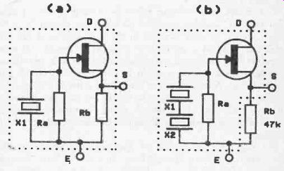
Fig. 16. The internal circuits for the FOO1P (a) and SR02 (b) passive IR sensors.
Normal semiconductor infrared devices work in the part of the light spectrum which is close to the red end of the visible light spectrum, or in terms of wavelength at around 850 to 950nm.
These are virtually useless for passive infrared detection where much longer wavelengths are involved (around 1 to 20p,m), and devices designed specifically for this application are required in order to obtain really good results. These devices have little in common with ordinary photodiodes and the like, and they are made from a material such as lead zirconate titanate and consist of a slice of the material with electrodes on opposite faces. When subjected to heating the device produces small opposite electrical charges on the electrodes, and this effect is similar to the more familiar Piezo electric effect which is utilized in such things as crystal microphones and ceramic pick-ups, and which generates a similar electrical signal when subjected to physical distortion.
Like a ceramic pick-up, the signal produced by a passive infra- red sensor, or "pyro" sensor as they are popularly known, is at a high impedance.
Practical pyro sensors are usually more than just the sensing element, and generally include a source follower stage to give the device a relatively low output impedance. Figure 16(a) shows the circuit for the FOO1P device, which has a single sensor, a junction gate field effect transistor to operate as the source follower, and built-in gate bias and source load resistors (Ra and Rb respectively). Some devices use a different arrangement, and Fig.16(b) shows the internal arrangement for the SR02 (or the almost identical SRA02). This has two sensing elements connected in series, but this is not done, as one might think, in order to simply double up on the output voltage from the device.
In fact the two sensing elements are connected in anti -phase, so that rather than adding together to give a stronger output, the two signals actually cancel one another out and give zero output.
This might seem to be completely pointless, and to understand the reason for doing this you must first understand the basic way in which these devices are operated. They are not simply used to detect the presence or absence of body heat, and although operation of this sort would be possible, it would give poor results in practice. There are two problems with this system, and one is simply that the shift in the DC output level produced by the sensor when body heat is detected is likely to be extremely small, even at short ranges. This gives problems in detecting the shift without spurious triggering of the circuit being caused by drift rather than heat being detected. The second problem is that of ambient heat producing signals that can produce spurious triggering and swamp the wanted signals.
Passive infrared detectors minimize these problems by using high gain AC coupled amplifier to boost the output from the sensor, but it is then changes in the infrared level that are detected, and not a continuous high level. Passive infra-red detectors are consequently movement detectors, and they will not respond to someone who is within the monitored area but keeping perfectly still. A lens system of some kind is used to convert the movement of someone within the monitored area into a burst of infrared radiation which sweeps across the sensor. This is an aspect of things which we will consider in more detail later in this Section.
Returning to the subject of dual opposed sensors; under quiescent conditions the output from the sensors is zero, since any infrared received by one element will almost certainly be received by the other one as well, and their output voltages cancel each other out to give zero volts (or a very low potential anyway, as perfect cancelling is unlikely in practice). When someone moves across the monitored area they cause a beam of infrared radiation to be swept across the sensing elements, with first one and then the other being subjected to the beam. This prevents any significant cancelling of the two output signals occurring, and results in first one sensor providing an output pulse and then the other providing a signal. The two signals follow one after the other with no real delay between them, and they are of opposite polarity, so that they effectively combine to produce a single output pulse of double the amplitude produced by a single sensing element.
Dual opposed sensors therefore have good immunity to background infrared and a relatively strong output signal when activated. They are comparatively expensive though.
The passive infrared circuit described here will work with a wide range of pyro-sensors, but obviously some will work better than others, and the exact level of performance obtained depends on the quality of the pyro sensor used. It is even more dependent on the quality of the optical system though, and it is primarily this factor which determines how well or otherwise the system will function in its intended application.
An important point to note is that some pyro sensors have an integral source load resistor whereas others require a discrete resistor. The FOO1P has a built-in source load resistor, but as shown in Fig.16(b), the SR02 requires an external 47k load resistor (as do the SRAO2, the SSC10, the RPY97, and most other pyro sensors). Where appropriate this resistor must be included, and the passive infra-red detector circuit will not work at all if it is omitted and no internal load resistor is present.
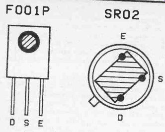
Fig. 17. Pinout details for the FOO1P and SRO2
Pinout diagrams for the FOO1P and SR02/SRA02 devices are shown in Figure 17. The FOO1P has an unusual encapsulation which consists of a rectangular plastic housing with the three leadouts coming from the base, and the window is situated at the front of the device. The leadouts are long enough to permit the device to be mounted horizontally if necessary. The SR02 and SRO2A are in a standard three lead TO-99 type metal encapsulation, but with a large rectangular window in the top of the casing (Figure 17 shows a top view of this device, as indicated by the position of the tab). Note that the window of dual element types is rectangular rather than round or square, and that in order to obtain good results the device must be orientated correctly.
The device must be arranged so that the beam of infrared radiation is swept from one element to the other, which means that the device will normally be positioned so that the window is horizontal and not vertical. Alignment does not seem to be very critical though, and errors as large as 45 degrees still seem to give good results. With a 90 degree error though, the system would probably give only very restricted range, if it worked at all.
Detector Circuit
The circuit diagram for a simple passive infrared detector is shown in Figure 18.
IC1 is the pyro sensor, and it has been assumed here that an FOO1P will be used, but the only modification required for an SR02, SRA02, or similar device, is to add a 47k load resistor from the "S" terminal to the 0 volt supply rail.
IC2a provides the first stage of amplification, and this device is operated in the non -inverting mode. It has a slightly unusual feedback circuit, and the point of this arrangement is to give a combination of high gain and good low frequency performance without the capacitors in the circuit taking a very long time after switch -on to reach their normal working charges. This type of feedback network is actually quite common in RIAA pre- amplifiers, but it is perhaps of even more benefit in this application where the circuit must have a good response well into ...
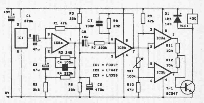
Fig. 18. The circuit diagram for the passive IR detector.
... the sub-audio or "infra-bass" part of the sound spectrum as it is sometimes called. In fact the signals from the pyro sensor will normally be at frequencies of around 0.5 to 2Hz, making the use of relatively large coupling and decoupling capacitors necessary.
It still takes several seconds for the circuit to settle down and start to operate properly, but with a more simple feedback arrangement it could take a matter of minutes instead of seconds.
C4 severely attenuates the high frequency response of the circuit, as well as quite low frequencies come to that. Frequencies of more than about 2Hz are not produced by the pyro sensor, and so this very restricted bandwidth does not adversely affect sensitivity. On the other hand, it does greatly reduce the output noise level of the amplifier and helps to give improved performance. In particular, it greatly reduces the possibility of spurious triggering, especially if the circuit is operated at high sensitivity.
IC2b acts as the second stage of amplification, and this is a standard inverting mode circuit. It again has a frequency response which is given a 6dB per octave roll: off at frequencies of more than a couple of Hertz, with C7 providing the filtering in this case.
The circuit operates from a single 9 volt supply rail with R5, R6, and C6 providing a centre tap on the supply rails for bias purposes.
The output from IC2b is normally at about half the supply potential, but it will swing slightly either side of its quiescent level due to noise on the output. When the unit is activated, the output of IC2b produces a much larger output voltage swing. The two operational amplifiers of IC3 are connected to form a sort of window discriminator, and if the output of IC2b goes positive by more than a certain amount the output of IC3a switches to the high state. If the output of IC2b goes low by more than a certain amount, then IC3b's output switches to the high state. In either case Tr1 is biased into conduction and the relay is switched on.
VR1 controls the amount by which IC2b's output voltage must shift away from the quiescent bias level before the relay is activated, and it therefore operates as a sensitivity control. It is important not t9 set the sensitivity too high because noise on the output from the amplifier would then cause frequent spurious triggering of the unit.
DI is the usual protection diode which suppresses any reverse high voltage pulse generated across the relay as it is switched off.
Do not be tempted to omit this - semiconductors are very intolerant of high voltages, and without Dl the unit could easily sustain a lot of expensive damage. The quiescent current consumption of the circuit is quite low at only about 2.5 milliamps, but it is substantially higher than this when the relay is activated.
The exact current consumption depends on the coil resistance of the relay, and is about 25 milliamps with a 400 ohm type. The circuit will operate with any relay that has a coil resistance of about 200 ohms or more and which will operate reliably from a nominal 9 volt supply. Obviously the relay must have contacts of the appropriate type and of adequate voltage/current rating, but the requirements here are totally dependent on your intended application for the unit.
Components for Passive IR Detector (Fig. 18)
Resistors (all 1/4 watt 5%)
R1 47k R2 2k2 R3 2M2 R4 220k R5 22k R6 22k R7 220k R8 2M2 R9 47k R10 47k R11 10k R12 10k Potentiometer
VR1 100k lin
Capacitors C1 220p. 10V elect
C2 47p 16V elect
C3 47A 16V elect
C4 100n polyester
C5 10p. 25V elect
C6 470p, 10V elect
C7 100n polyester
Semiconductors
IC1 FOO1P (see text)
IC2 LF442
IC3 LM358
Tr1 BC547
D1 1N4148
Miscellaneous
RLA1 Relay with coil suitable for 9 volt and coil resistance of about 200R or more (contacts and ratings as required) Fresnel lens (see text), circuit board, control knob, case, etc.
N.B.
The FOO1P was available at the time of writing from Maplin Electronic Supplies Ltd., P.O. Box 3, Rayleigh, Essex SS6 8LR.
The SRA02, and SSC10 pyro sensors, the CE24 fresnel lens, and window material were available at the time of writing from Chartland Electronics Ltd, P.O. Box 83, Cobham, Surrey KT11 2QB.
Construction As far as the electronics are concerned there is little of difficulty in building this unit. Although it has very high gain there is relatively little risk of instability as the amplifier section of the circuit has such a limited bandwidth. Care to avoid earth loops should be taken though, and the supply needs to be reasonably stable if the unit is to give reliable results.
The mechanical side of construction is far less straightforward as there is the optical system to contend with. Where a fairly large area is to be monitored a fresnel lens designed specifically for this application offers the best performance, and a range of up to about 10 meters over a wide angle of coverage is possible. The basic set up used with a fresnel lens is shown in Figure 19.
The lens is a piece of flexible plastic which is positioned in front of the pyro sensor and given the appropriate degree of curvature.
The lens is effectively a large number of lenses combined in one unit, or "multi -faceted" as it is usually termed.
Its basic effect is to give "blind" areas where the unit is very insensitive, with areas of high sensitivity in-between them. This breaks the monitored area up into a number of zones of high and low sensitivity, and there is typically two dozen or more zones of high sensitivity.
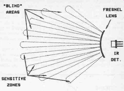
Fig. 19. A fresnel lens divides the monitored area into zones of high and low
sensitivity.
Although I stated earlier in this Section that passive infra-red detectors are a form of movement detector, not just any form of movement will do. In common with most types of movement detector they are very sensitive to movement in one direction, while being almost oblivious to movement at right angles to this.
In the case of a passive infrared detector it is movement across the monitored area that is most readily detected, as the person detected by the unit then moves rapidly from a sensitive zone to an insensitive one, on to another sensitive zone again, and so on, giving a series of strong output pulses from the pyro sensor. In theory, anyone moving straight towards the sensor will not cross from one zone to another and will not activate the unit. In practice, this seems to produce sufficient variation in the infrared level received by the pyro sensor to trigger the unit, although the range is very much less for movement in this direction. Note that the directions which give optimum and minimum sensitivity are the opposite to those of Doppler shift type detectors, such as the popular ultrasonic detectors used in burglar alarm systems. If you are used to dealing with Doppler type detectors you will need to bear this fundamental difference in mind when deciding on the best position for an infrared detector. Correct sighting of the sensor is essential if the unit is to give good results, and with (say) a unit intended for use in a system which provides automatic operation of doors, the obvious method of having the sensor above the door and aimed out into the room would actually be very ineffective. The unit would work much better placed to one side in the room so that anyone approaching the door would pass from zone to zone several times, and would almost certainly trigger the unit.
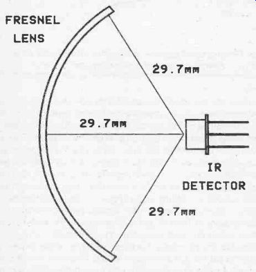
Fig. 20. The fresnel lens must be given the correct curvature.
The fresnel lens I have used is a CE24 type which, although a relatively inexpensive type, provides good performance. It is virtually a flat piece of plastic as supplied, and it must be given a form of mounting that provides the correct curvature. As shown in Figure 20, the ideal curve is one which keeps the distance from the window in the pyro sensor to the fresnel lens at 29.7 millimeters. The sensor should be positioned so that it is about half way up the lens, and remember that with dual element sensors the window and the lens should be aligned properly.
If you are trying to stretch the range of the system to its limits it is important to have the lens and pyro sensor mounted as accurately as possible. In practice there does not seem to be any great loss of performance if small inaccuracies are allowed to creep in, and quite good results often seem to be produced if the mounting of the lens and (or) the pyro sensor are far from totally accurate. The importance of having the lens and sensor accurately placed therefore depends largely on the level of performance required, but probably few constructors have the tools to permit precision mounting of these two components anyway.
I found that good results could be obtained by making a cutout in the front panel of the case about 48 millimeters wide by 45 millimeters high, and then beveling the side edges of this. The idea here is to glue the lens in place on the beveled edges, with the lens having been curved to enable it to fit into place. It is easily glued in place using a good quality general purpose adhesive, and as the lens tries to uncurl it tends to force itself tighter into the cutout, so that the glue has to provide little adhesion initially in order to prevent the lens from falling out of place while it sets.
Note that the lens is designed to have its smooth surface facing outwards. It is advisable to use small pieces of thick card or sheet plastic to fill in the semicircular areas at the top and bottom of the lens. Otherwise these gaps could encourage turbulence around the pyro sensor which could result in spurious triggering of the unit. The pyro sensor must be fitted centrally behind the lens and 29.7 millimeters (or thereabouts) behind it, and this is a matter of designing the unit so that the circuit board can be positioned to bring the sensor to the correct place. If you are using the FOO1P this will probably be easier if it is mounted horizontally. Spacers and washers over the board's mounting screws can be used to set the sensor to lens distance correctly.
An alternative method is to shape two pieces of sheet plastic material (or even just copper laminate board) so that they can be mounted on the printed circuit board, and the lens can then be glued in place over them so as to give the correct curvature. Of course, things must be arranged so that the pyro sensor fits on the right part of the board so that it is brought centrally beneath the lens, and it should be mounted at the appropriate height above the board to give the correct sensor to lens distance. This method is a somewhat neater way of doing things, but when trying this I found it to be less easy than one would expect. There is no real problem in shaping the end cheeks with the correct 29.7 millimeter curve, but I found it quite difficult to get the whole assembly to fit together strongly and reliably. It requires the use of top quality adhesives plus a fair amount of skill and patience.
With this second method a large cutout is still required in the case in order to provide the sensor and lens with a window for the infrared radiation to pass through. In order to give the unit a neat finish some window material can be glued in place behind the cutout, and special window material for this application is available. Ordinary window material for use with LED displays etc. is unlikely to be much use in the present application.
Shutter
Where a range of only a few meters is required it is not necessary to resort to a lens at all, and simple shuttering can be used to give zones of high and low sensitivity. Actually, where high sensitivity is not needed it is probably best not to use a lens as apart from unnecessary expense it could also result unwanted triggering of the unit by people who should be out of range, and the shuttering system probably represents a much better choice.
This basic idea is shown in Figure 21, and all that is required is a sheet of material having (say) vertical slits placed in front of the sensor so that it can "look" through the slits to some parts of the monitored area, but is shuttered off from others. Around ten or twelve slits should be sufficient to give good results, and some window material can be fitted over the shuttering in order to discourage turbulence around the pyro sensor. A more simple method which might give good results would be to drill vertical rows of holes rather than to cut slits.
When deciding on the placement of the unit it is as well to bear a few points in mind. First and foremost, as explained previously the unit is most sensitive to people moving across the monitored area and is least sensitive to people moving straight towards the sensor so that they do not move from one zone to another. It is therefore essential to position the unit such that in normal operation people will be moving across the monitored area and optimum reliability will be obtained. Do not forget that it is infra -
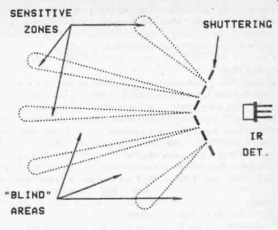
Fig. 21. Using a simple shutter arrangement to give zones of high and low
sensitivity red radiation that the device detects, and it will therefore respond
to anything that provides a suitable signal and not just people.
Infrared systems are generally thought to be less prone to spurious triggering than most other forms of movement detector, and the unit should not be triggered by something like a moth flying through the monitored area (which is sufficient to trigger most ultrasonic types). It is possible for units of this type to be triggered by something like the warm turbulent air from a radiator, and the unit should not be aimed at any obvious sources of infrared energy. Although units of this type are often mounted quite high up in a room, this is not necessarily the ideal place for them. If they can be accommodated at a height of around 1 to 1.5 meters this is where optimum results are likely to be obtained.
Units of this type are less than ideal for use out-of-doors where turbulent air can tend to cause unwanted triggering. They seem to be much better than ultrasonic alarms in this respect though, and when experimentally trying out a system outside it seemed to give reliable results provided the sensitivity control was set back slightly from the maximum usable indoor setting. Setting the sensitivity control is always a matter of trial and error, in an attempt to find a setting that gives adequate sensitivity but which does not result in spurious operations of the unit.
Broken Beam
Broken beam type detectors usually utilize an active system where a pulsed beam from a transmitter is aimed at a separate receiver circuit some distance away, and anyone moving through the beam momentarily cuts off the signal to the receiver and activates the system. It is possible to have a passive broken beam type circuit though, albeit with a somewhat lower maximum range than can be achieved with a conventional set up. It is not a true broken beam detector in that there is no beam of infrared energy, and what is really happening is that a lens is used to give a passive infrared detector a very narrow corridor of high sensitivity, and anyone crossing through this "beam" produces an output pulse from the pyro sensor that triggers the electronics.
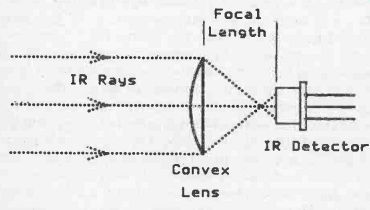
Fig. 22. Using a lens to make the detector highly directional.
Although a system of this type has the disadvantage of relatively low range, a maximum range of as much as 30 meters can be achieved, and this is perfectly adequate for the vast majority of applications. Actually it is possible to obtain sufficient infrared pick up at greater ranges, but there is a problem with the beam spreading as the range increases. This means someone crossing through the beam at extreme range will take a relatively long time to do so, and this can result in an output pulse from the sensor of such low frequency that the amplifier does not respond to it properly, and the device is not triggered.
The lens system for a broken beam type alarm is relatively simple, and all that is needed is an arrangement of the type shown in Figure 22. The lens is a piano convex or double convex type, and it should have a diameter of around 25 to 40 millimeters and a focal length 'a about 20 to 50 millimeters. The pyro sensor is positioned centrally behind the lens, and at a distance from it which is equal to the focal length of the lens. The lens has the effect of gathering up infrared radiation over a relatively large area and concentrating it onto the sensor. In this way it effectively provides gain and boosts the range of the sensor. It only correctly focuses light that comes from almost directly in front of the lens, and this makes the system highly directional so that the narrow corridor of high sensitivity is obtained.
Although a system of this type is very simple in theory, there is a major problem in practice. This is due to the fact that most lenses are intended for operation in the visible light part of the spectrum, and they may not work well at long infrared wavelengths. This might result in no more than a slight change in the focal length of the lens, making it necessary to shift the pyro sensor backwards or forwards slightly in order to obtain optimum results. In an extreme case the lens could be virtually opaque to the wavelengths involved here, making it totally unusable in the present application.
A lens specially produced for this application is available, and it is advisable to use this rather than to obtain a lens which is fine in theory, but may well be completely useless in practice. In this application a single element pyro sensor such as the FOO1P or SSC10 seems to be preferable to a dual element type. The circuit of Figure 18 is perfectly suitable for operation as a broken beam type unit, if used with a suitable lens system of course.
Modifications
As described so far, the system merely provides a switching action from the relay when someone is detected in the monitored area.
The relay does not latch in the "on" state, and it might not even stay switched on for the whole time that someone is within the monitored area. What normally happens is that someone moving within the unit's field of view causes the relay to switch on and off as they move from one zone to another. In some applications this is perfectly satisfactory, and in a burglar alarm system for example, the relay contacts would be wired into the loop of switches along with door and window switches, and once activated it would be the alarm that would provide the latching action.
Similarly, in many automatic control applications it is merely necessary for the sensor circuit to provide a switching pulse which sets things in motion. The control circuit then provides its own reset pulse (or it is provided via some mechanics in the system) when it has completed the task (opening a door, or whatever).
For some applications it is necessary for the circuit to either provide latching, or to at least provide a hold -on so that once activated the relay remains switched on for some period of time.
In the case of built-in latching, this would be required if the unit was to be used as a stand-alone burglar alarm rather than as part of a system. The hold -on is required in an application such as automatic lighting, where it is needed to prevent the lights from being flashed on and off as someone moves around the room. It would also prevent the lights from switching off simply because someone kept fairly still for a while.
Taking the hold-on problem first, this is easily solved by modifying the output stage of the unit, as shown in Figure 23. D2 and C8 form a simple charge storage circuit, and when one of the outputs of IC3 goes high C8 is charged to about half the supply voltage. D2 blocks any flow of current back into R11 or R12 and the output stages of IC3, and the only discharge path for C8 is through R13 and into the base of Tr1. When the unit is activated, C8 is almost instantly charged via the relatively low source impedance of the drive signal, but the input impedance into Tr1 is very high, giving a much longer discharge period. The input impedance to Tr1 is made suitably high by using it as the first device in a Darlington Pair which is comprised by Tr1 and Tr2.
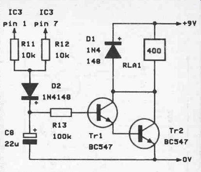
Fig. 23. Adding a hold -on facility to the unit
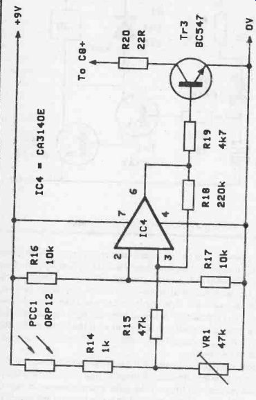
Fig. 24. A simple inhibitor circuit for use in an automatic lighting application
The practical result of this is that once triggered, the relay remains switched on for some time even if no further triggering occurs. The hold-on time is controlled by the value of C8, and with the specified value the relay should hold-on for half a minute or more after triggering (the exact time will vary considerably from one unit to another). If required, the hold-on time can be increased by using a higher value component in the C8 position, or decreased by using a component having a lower value. The delay time is proportional to the value of this component. Note though, that if C8 is made too high in value it will take a long time to charge up to a potential that switches on the relay, giving the unit what might be an unacceptably slow switch-on characteristic. In a lighting application it is probably best to use a fairly long hold -on time, since it is probably better to have the light remain switched on for a minute or so after everyone has left the room, rather than to have the light occasionally switching off while someone is present in the room.
Automatic lighting is one of those things which is not quite as simple and straightforward as it might at first appear. An infrared detector system will turn on the light when someone enters the room, and keep the light switched on for as long as they stay in the room and move slightly from time to time, but it will do so regardless of whether it is dark or not. The most simple way of preventing this is to use a photocell circuit, such as the one provided in Figure 24, to deactivate the unit in daylight.
PCC1 is a cadmium sulphide photoresistor, and its resistance decreases as the light level to which it is subjected is increased. In this circuit it is connected as part of a potential divider network wired across the supply rails, and the output voltage of this circuit rises with increased light level. IC4 is an operational amplifier, but it is operated as a Schmitt Trigger circuit in this case, and its output triggers to the high state if the light level is above a certain level. This trigger threshold can be varied by means of VR1 which consequently operates as a sensitivity control. When the light received by PCC1 is above the threshold level and IC4's output triggers high, Tr3 is switched on and it holds C8 in the discharged state. The required action is thus provided, with the sensor circuit being held in the "off' state when the ambient light is above the threshold level.
Note that even if the unit is already triggered and the ambient light goes above the threshold level, the artificial lighting becomes unnecessary and the unit will automatically switch it off. R18 introduces a certain amount of hysteresis to the trigger circuit, and this gives a higher light level at which the sensor becomes inhibited than the one at which it is enabled again. This, together with the triggering, ensures that the sensor is always fully enabled or totally cut off and does not hover at some intermediate state, and it also prevents the lighting from being repeatedly switched on and off when the ambient light is close to the threshold level.
An essential point to bear in mind with a circuit of this type is that it can only function properly if the photocell is mounted where it will receive the ambient lighting, but will not be subjected to the output from the lamp that is being controlled. Otherwise there is a strong likelihood of the system breaking into oscillation, with the lamp being switched on, the photocell detecting the increased light level and switching it off again, the reduced light level resulting in the sensor being activated again with the light being switched on, and so on.
It will often be necessary for PCC1 to be remotely located from the main unit so that it can be kept away from the controlled lamp, and a connecting cable a few meters in length will then be required. This is perfectly acceptable, but the connecting cable should be a twin screened type. The inner conductors should carry the two connections to PCC1 while the outer screening should be earthed to the 0 volt supply rail.
Additional Components for Inhibitor Circuit (Fig. 24)
Resistors (all 1/4 watt 5%)
R14 1k R15 47k R16 10k R17 10k R18 220k R19 4k7 R20 22R
Potentiometer
VR1 47k sub-min hor preset
Semiconductors
1C4 CA3140E Tr3 BC547
Miscellaneous
PCC1 ORP12
Latching
Latching can easily be added to the infrared detector circuit, and very few additional components are required, but a basic latch circuit will often be of little practical value. The first problem is that of the unit tending to trigger at switch on due to the voltage changes that occur as the capacitors in the circuit assume their normal working charges. To the output stage these are in distinguishable from the signals produced when the unit is activated, and they would latch the relay in the "on" state. This could be overcome by manually resetting the unit after a few seconds, but this is obviously an unsophisticated and inconvenient way of doing things.
Another problem is that of getting away from the unit without triggering it. The standard burglar alarm answer to this problem is to have a delay which holds the unit in an inactive state for about half a minute so that the person switching on the device has plenty of time to get out of range before the unit becomes fully active.
This method also overcomes the problem of the unit triggering itself at switch -on. Figure 25 shows the circuit diagram for a latching output stage which incorporates an "exit" delay facility.
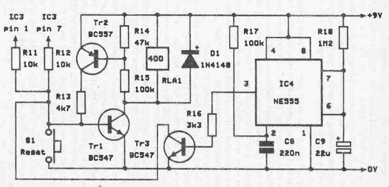
Fig. 25. The circuit diagram for the latch and exit delay
R11, R12, Tr1 , RLA1, and D1 are the original output stage, and as before, when one of IC3's outputs goes high Tr1 is biased into conduction and the relay is switched on. The latching is provided by Tr2, and under quiescent conditions this device is switched off and has no effect on the circuit. However, when Tr1 turns on, the voltage developed across R14 and R15 is sufficient to bias Tr2 into conduction. It then provides Tr1 with a base bias current via current limiting resistor R13, and this current holds Tr1 in the "on" state even if both of IC3's outputs now take up the low state again.
S1 is a "reset" switch, and when operated it short circuits the base of Tr1 to the negative supply rail. This switches off Tr1 which in turn cuts off the relay and Tr2. The relay therefore remains switched off when S1 is released, unless the unit is reactivated of course. The unit can also be reset by simply switching off the power for a second or two and then switching it on again. This is not quite the same as operating S1 in that pressing S1 only resets the latch, and it does not start a new exit delay cycle. On the other hand, switching off and then turning the unit on again does start a new exit delay period as well as resetting the unit.
If a basic latch is all that is required, then the rest of the circuit (which provides the exit delay facility) is unnecessary. The device at the centre of the delay circuit is IC4, and this is a 555 timer device operated in the standard monostable mode. It is provided with a trigger pulse at switch -on by the C-R network, Rr - C8.
R18 and C9 are the timing components, and the specified values give an exit delay period of approximately half a minute. The output pulse duration is about 1.1 CR seconds, and by using suitable values is it possible to obtain any desired delay time from a fraction of a second to a few minutes. There is no point in using very short pulse durations in this application, but in certain circumstances a longer delay might be helpful. In theory it is possible to obtain very long delay times, but in practice the high values that would be needed for R18 and C9 would probably result in failure. With a high value for the timing resistor and C9 having a high value as well, the result could be that the charge current would be matched by the leakage current. The voltage on C9 would then cease to rise, and the two thirds of the supply voltage threshold level at which the timing periods ends would never be reached.
To avoid this it is advisable to keep the value of R18 at no more than about 2M2, and to use a tantalum bead capacitor for C9.
These components have much lower tolerances and leakage levels than ordinary electrolytic capacitors, and they therefore offer much more predictable results as well as better reliability. The maximum value in which tantalum bead capacitors are readily available seems to be 100p., which with a. 2M2 timing resistor represents a delay time of just over 4 minutes (4 minutes and 2 seconds to be precise), which should be more than sufficient.
The positive output pulse from IC4 is used to switch on Tr3 which operates as a common emitter switch. It is connected in parallel with S1, and holds the latch in the reset state until the end of the timing period when Tr3 is switched off.
Of course, in a stand-alone burglar alarm application an alarm generator of some kind will be needed, and in its most basic form this can just be the usual alarm bell activated via a set of normally open relay contacts. If preferred, a more sophisticated set-up can be used, such as an electronic alarm generator having facilities which could include an entrance delay and automatic switch-off after a preset delay.
Additional Components for Latch and Exit Delays (Fig. 25)
Resistors (all 1/4 watt 5%)
R13 4k7
R14 47k
R15 100k
R16 3k3
R17 100k
R18 1M2
Capacitors
C8 220n polyester
C9 22p, 10V tantalum bead
Semiconductors
IC4 NE555
Tr2 BC557
Tr3 BC547
Miscellaneous
S1 push to make - release to break type
Finally
By using the basic sensor circuit with a suitable optical system and, where necessary, one of the modified output stages, it can operate in a wide variety of applications, including such things as burglar alarms, automatic lighting, and automatic doors. Passive infrared detection is also something which represents an interesting field for the experimenter, and is something which is well worth investigating just for its interest value and even if you have no obvious use for equipment of this type, you will probably soon discover one or two.