Nearly all loudspeakers in use today make use of a principle patented as far back as 1898 by Oliver Lodge, and later developed into a workable loudspeaker by Rice and Kellogg, which they patented in 1925. It says much for their design that it has changed only in details and materials used, since then. It is the moving-coil system.
If you have an old loudspeaker lying around, dig it out and take a close look at it. It may be round or elliptical, but whichever it is, the frame or chassis supports a magnet at the back in most cases, although a few have it at the front (Fig. 1)
Cone Surround
The cone is usually made of paper and is fixed around its outer edge to the frame either directly or by means of a flexible roll of cloth, sponge or rubber. The roll can be either a half-roll out in which the roll faces outward or a half-roll in whereby it faces inward toward the back of the speaker. When the cone is fixed directly to the frame, there are corrugations around the perimeter; these can be of two sine rolls, a single sine roll or a deeper accordion pleat.
The purpose of these are to permit forward and backward motion of the cone while holding it firmly against any sideways movement, but they also have another important function.
When the cone vibrates, ripples can spread out from the center like ripples in a pond when a stone is thrown in. If you observe pond ripples closely, you will notice that if they encounter a hard boundary such as a stone sidewall, they are reflected back across the surface, but if they meet a soft perimeter of reeds grass or mud, they are mostly absorbed and very few are reflected.
In the case of the loudspeaker cone, reflections are undesirable as they produce spurious cone motion that is not in response to any electrical output from the amplifier. So a necessary function of the surround is to absorb and dampen such vibrations thus eliminating reflections.
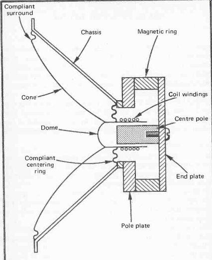
Fig. 1. Moving coil bass driver.
Cone Materials
Really, to avoid ripples and flexures which can color the reproduction even before they may be absorbed by the surround, it is desirable to make the cone as stiff as possible.
When a pond surface is frozen hard, ripples, waves or any other disturbances are not possible. Similarly, a perfectly stiff cone would move like a piston, backwards and forwards without any flexures, and so should radiate air pressure waves that are a perfect replica of the electrical currents flowing through the speaker circuit.
So why not make the cone of metal such as aluminum? They have, but that exchanges one set of problems for another. Metal cones tend to 'ring' when subject to vibration, like a bell when it is struck. Most hollow metal cans or boxes give a distinctive sound when flicked with a striker such as a pencil. An ideal loudspeaker cone should have no sound of its own at all, if it has, it will color the sound it reproduces.
Another problem is inertia. The loudspeaker cone must accelerate and decelerate very quickly in order to produce the very fast vibrations that make up a complex sound wave. To do this its mass must be low. A motor bike will always be away quicker from the lights than an articulated lorry in spite of having a much smaller engine, because its mass is a tiny fraction of that of the lorry. Metal cones, even aluminum ones, are much heavier than other materials commonly used, so they have a disadvantage here too. Honeycombed aluminum is light and about a thousand times more rigid than paper, but has not proved popular.
Polystyrene (same material as ceiling tiles) reinforced with aluminum foil is very light and rigid and has been used. Its snag is poor damping, it has a characteristic sound which is similar to that heard by tapping a ceiling tile held by one hand at its edge.
Bextrene has been used in many hi-fi speakers being stiffer and more consistent in its characteristics than paper. It too has poor damping and needs to be coated with a plastic damper to tame it. Polypropylene is a more recently employed material and seems to have advantages as a cone material. It is light, has good self-damping, and is more rigid than paper.
So we come back to paper again. If you tap the paper cone of a loudspeaker, all you hear is a dull plop without any readily identifiable sound. This is the ideal for uncolored reproduction. It is also very light, so the lack of stiffness is the only major snag. As we shall see later though, in certain circumstances this can be made use of and turned into an advantage.
Again it is a remarkable fact that the maternal which has been used for decades, is still the most widely used and hard to beat in spite of all our modern technology.
The paper pulp stock from which loudspeakers cones are made consists of wood and rag with various additives. One stock commonly used is kapok, which is produced from the hollow, oily fibers from the silk-cotton tree. These are especially light and strong and so are well suited for this purpose. Waxes, resins and fungicides are added.
Different characteristics can be imparted to the paper pulp stock by the length of the period for which it is beaten out in vats. Long periods produce short fibers which result in thin hard paper. Cones made from this are light and sensitive, though prone to resonances and poor damping.
They are thus more suitable for low-fi transistor radio speakers. Short periods of beating give long fibers, that are more flexible and so less rigid. These are best suited for bass speakers or full-range controlled flexure speakers. It is thus possible to produce a paper for a specific cone application, which is another reason why paper is so popular with the manufacturers.
Cone Resonance
Every physical object has a fundamental resonance, that is a frequency at which vibration is greater than at any other for the same input of energy. Loudspeaker cones are no exception, which means that sound output at the resonant frequency is greater than at all others. The result is an uneven frequency response with an unnatural emphasis at that one frequency.
Below the cone resonant frequency, the sound output falls off at a rate 12 dB per octave, so the frequency response in the bass region is determined to a considerable extent by the resonant frequency which should therefore be as low as possible.
The resonant frequency in free air is proportional to the square root of the reciprocal of the mass of the cone times the compliance of the suspension. The formula is:
fr 1/ 2 pi __/MC
… in which M is the mass in grams and C is the compliance in meters per newton ^-7 .
Compliance, which is the opposite hence the reciprocal of suspension stiffness, can be calculated from the cone mass and the resonant frequency as follows:
Thus the compliance (the opposite of stiffness) and the mass should be high, but if they are too high other problems can arise. If the suspension is too compliant it may not keep the cone in place at high volume levels; while if the mass is too great, more energy is required to move the cone hence the speaker sensitivity is low and a large amplifier power is needed.
The resulting high power dissipation in the coil causes heating with the undesirable effects noted later. Furthermore, as a large mass results in high inertia, the cone will not respond to rapid high frequency electrical signals.
Delayed Resonance
In addition to the resonance due to the effects of mass and compliance there is another. We saw earlier how ripples can move outward from the center of the cone to the rim and if not absorbed by the suspension are reflected back to the center.
When the cone radius equals one wavelength or a multiple of it, the high and low points of the outward and reflected ripples coincide to produce an apparently stationary ripple or undulation of the cone. It is therefore known as a standing wave However, when the applied electrical signal ceases, the standing wave subsides, and the consequent cone motion radiates sound as it does so. Stored energy is thus released as spurious sound after the cessation of the signal. The effect is thus termed delayed resonance. For an 8-inch cone, the fundamental delayed resonance is at 4 kHz with harmonics at 8 kHz and 16 kHz. Efficient absorption by the cone surround is vital to minimize the effect.
Another spurious motion performed by some cones at certain frequencies is what is known as the bell mode, with this, opposite quadrants of the cone perform a flapping movement in unison, moving backwards and forwards together while the adjacent quadrants flap in the opposite directions. However, two lines at right angles across the cone which define the boundaries of each quadrant remain stationary relative to the flapping. This effect is due to lack of stiffness of the cone itself.
The Coil
Continuing our examination of the loudspeaker, we come to the center of the cone. Here a dome is usually found concealing what lies beneath, and this serves as a dust shield to prevent foreign particles from getting into the air gap and causing grating noises. At certain high frequencies, this dome sometimes moves independently of the cone, by reason of the compliance of the glued joint. It thereby exhibits its own resonant frequency which colors the reproduction. To avoid this in some models, the dome is molded as an integral part of the cone.
Under the dome at the apex of the cone, the coil which consists of a number of turns of copper wire wound on a paper, composition, or aluminum cylinder, is fixed.
To reduce the mass and thereby the inertia in high frequency speakers, aluminum is sometimes used instead of copper wire.
To get as many turns as possible within the magnetic field, the wire is often of square, hexagonal, or ribbon configuration instead of round section, thereby saving space, eliminating air gaps between windings, and so permitting more turns per inch.
Up to 40% greater conductor density can thereby be achieved, thus making for a more efficient motor system.
The standard impedance of the coil, often termed the speech coil or voice coil, is 8 ohms, but 4-ohm and 16-ohm models are also available. Formerly, 3-ohms was the standard with 15-ohms for larger units, and these may still be encountered.
The impedance consists of resistance and inductance in series, the resistance making up approximately 2/3 of the rated impedance. So the impedance of an unknown speaker coil can usually be determined by adding half as much again to the measured d.c. resistance.
The impedance may be considered a minimum value as it rises to a peak at cone resonance, and is usually above the rated value over most of its frequency range. This is of no importance, but if the impedance should drop below the rated value it could cause overloading of the amplifier. Usually, a higher impedance than that of the amplifier output rating means less power, but often lower distortion, whereas a lower impedance produces higher distortion and possibility of amplifier overload with damage to its output stage.
Overloading results in less power being available before drastic distortion sets in. So reduced power results for speaker impedances that are either higher or lower than the amplifier rating, but higher is better and safer.
In multi-speaker systems with complex crossover networks, the total impendence may be mostly reactive at certain frequencies with the result that the output current and voltage are out of phase. Thus high currents may flow at relatively low powers so causing amplifier current-limiting circuits to clip prematurely.
Effects of Heat
Heat is generated in the coil by the current flowing through it, and the resistance rises by some 0.4% per degree C. Modern high-power rated speakers have coils wound on aluminum formers secured by high temperature epoxy resin adhesives and can withstand temperatures up to 300°C. Much lower temperatures are produced at the rated power, but a problem arises with multi-speaker systems. There can be differences in temperature between the bass and treble units due to the different frequency range handled by each, of more than 100°C. Thus there can be a difference of 40% in coil resistance between the two compared to that when cold. Furthermore the difference varies according to the program. Tonal balance therefore can change during a performance (Fig. 2).
An unexpected result of all this is that amplifiers having large amounts of distortion, such as when operating near their maximum power rating, heat up the treble unit more than low distortion amplifiers. This is because the distortion generated consists of spurious high frequency harmonics which are ...
----------
Program Bass driver Tweeter l Piano ff 100°C 25°C
Orchestra ff 150°C 40°C
Heavy rock ff 120°C 75°C
Fig. 2. Typical coil temperatures.
-------------
... reproduced by the treble unit. Now high-power amplifiers are not likely to be operated anywhere near their maximum rating, so we have the seemingly strange result that a low-power amplifier is more likely to overheat the treble-unit coil than a high-power amplifier.
To minimize the effect of heat, various measures are employed to remove it quickly and reduce the temperature build-up. Large magnet assemblies help and sometimes these are blackened and provided with heat fins, but these are long term devices and have little effect on short term temperature variations produced by changing program content. Treble units being smaller, have a lower maximum temperature than bass drivers, around 120°C. To aid dissipation, some units have gaps between the coil and magnet poles filled with colloidal ferromagnetic fluid held in place by the speaker's magnet. This also slightly increases efficiency and provides a measure of damping.
The Magnet
Returning again to our exploration of the speaker, we find at the back there is a ring of flexible material with corrugations that is secured to the framework at its outer edge and to the cone at its inner. This has the important function of keeping the cone centered relative to the magnet poles. With cheap speakers as used in many transistor radios, the cone can become off-center due mostly to warping of the thin metal frame so that the magnet poles are not true.
An off-center cone produces distortion as it rubs against the magnet pole and can be tested for by standing the speaker on its magnet, face upward, and gently pressing the cone inward with the thumbs at opposite points across the diameter, then releasing it. Any rubbing can usually be felt, or heard if an ear is placed close to the cone. Sometimes though, trouble may be experienced from loose coil windings and these may not be detected by this test.
The magnet usually consists of a magnetic ring or rod mounted axially at the back of the speaker. The front pole is terminated by a steel rod pole piece which penetrates inside the coil, and is only slightly of smaller diameter so that the air gap between it and the coil is small. The rear magnet pole is extended by a cylinder or U piece toward the front, where it terminates in a plate with a hole or a ring that surrounds the outside of the coil (Fig. 3).
The magnetic field is thus concentrated between the internal rod and the inside of the surrounding hole and thereby through the coil windings. As with all magnets there is a small external leakage field, but modern speakers are designed to reduce this to a negligible amount. It may seem, when trying to attract a ferrous object with a speaker magnet, that the magnet is weak, but this is the reason. For the same reason there is little possibility of erasing a magnetic tape from the stray field from a modern speaker, this danger is often greatly exaggerated.
Connections from the coil are taken to a couple of soldered blobs on the cone from which highly flexible stranded copper wires connect to a terminal strip on the speaker frame. These wires must never be tight nor must they loop down to touch the cone at any other than their soldered connection; they must be completely free of all obstruction. Failure to ensure this could result in buzzing noises as the cone vibrates.
Dedicated Drivers
To achieve an extended low-frequency response, the mass of the cone needs to be large so that it has a low resonant frequency. Furthermore, its diameter should also be large because the efficiency of the cone falls with decreasing diameter at low frequencies. However, to obtain a good transient and high-frequency response the cone should be small and light.
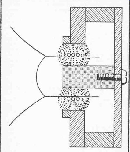
Fig. 3. Close-up of coil in magnetic field showing flux distribution.
These conflicting requirements have led to the general use of separate drivers for treble and bass, commonly known as tweeters and woofers. The signal is split into two, one containing all the high frequencies and the other the low by a filter circuit termed a crossover network and fed to the respective drivers. A mid-frequency range speaker is also used in some models, and some have super-tweeters and sub-woofers to extend the range to inaudibility in the treble and bass.
Disadvantages
One of the disadvantages of having a separate tweeter is that of its physical displacement as a sound source. All high frequencies thereby come from a different point in space from the low frequencies. Several ill effects arise from this.
The resulting sound field does not correspond with that heard by the microphone. Ideally, the sound radiation for each channel should be from a point source, then the stereo positioning can be accurately re-created. To achieve this ideal perfectly is not practically possible, but the aim should be to get it as small as one can. The use of separate drivers enlarges the radiation source and thereby blurs the stereo image.
Another effect is caused by the fact that the cut-off at the crossover frequency is not abrupt but gradual. At and around this point both bass and treble units are handling the same signal. If the tweeter is mounted above the bass unit as it usually is, the output will diminish at points that are higher or lower than the horizontal axis. This is because the difference in distance from each driver to those points delays the sound from the furthest, and so produces partial cancellation (Fig. 4).
A similar effect is due to the bass unit having a much deeper cone than the tweeter. If both are mounted in the same plane, its main radiating area is thus further from the listener than that of the tweeter. At frequencies corresponding to a half wavelength difference, cancellation can be total if both units are radiating the same acoustic energy. Equal radiation can take place only around the crossover frequency, so the effect is greatest when the cancellation and crossover frequencies are actually or nearly the same. So for example, at a depth difference of 2 inches the cancellation frequency is 3.36 kHz.
Normally crossover frequencies are lower than this, but partial cancellation will still occur at other values (Fig. 5).
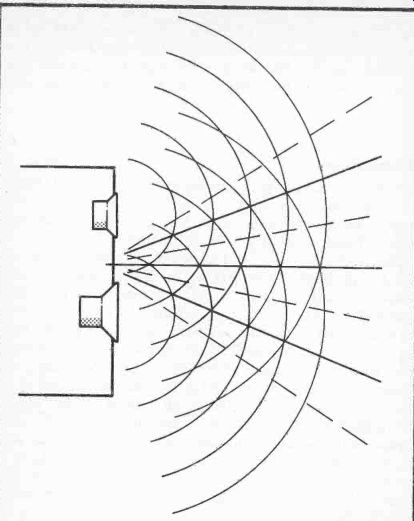
Fig. 4. When bass and treble units are reproducing the same frequency,
physical displacement produces radial areas of reinforcement (solid lines)
alternating with areas of cancellation (dotted lines).
Frequency response thus depends on listening elevation.
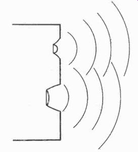
Fig. 5. Difference in cone depth Between bass and treble units produce
phase differences in frequencies reproduced by both and partial cancellation.
Further disadvantages come from the need for a filter circuit to separate the frequency bands, but we shall deal with these in a later section.
Co-Axial Drivers
Some of the disadvantages we have discussed can be avoided or minimized by mounting the tweeter in front of the bass driver. This achieves an effect closer to a point source, but there is still the depth difference and the need for a filter circuit. A separate tweeter supported on struts across the face of the bass unit is one way of achieving this, but a more satisfactory way is to use a co-axial driver (Fig. 6).
This is a speaker having two integral cone systems, the treble within the bass cone. The advantage off this over the use of separate concentric drivers is that the two systems are designed ...
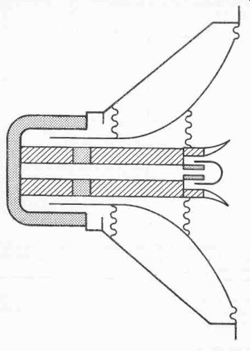
Fig. 6. Coaxial driver. The tweeter is within the cone of the bass unit.
Interference and phase differences are thus avoided.
... to be compatible, and the treble one is closer to the apex of the bass, so depth difference effect is reduced.
A disadvantage of having an obstruction such as a tweeter unit whether separate or integral, in front of the bass cone is its effect on mid frequencies just below the crossover. An acoustic shadow is cast when an obstructing object is of comparable area to the wavelength of the sound. Furthermore reflections back to the bass cone can be caused which produce cancellation and reinforcement effects. Because of the dimensions involved, these have their main effect in the mid-frequency range.
With well-designed co-axial drivers, the tweeter components are shaped to minimize these effects and very good results can be obtained. However, it is impossible to tell whether these problems have been tamed in any particular model without a period of listening, and if it is then found that they haven't, it is too late! Early models were not too successful on these counts so they never really became popular. Another more mundane reason is that the more drivers a loudspeaker system has for the same price, the better value it appears to be. So single drivers even though they are two units in one, are less likely to be a commercial success than competitors having separate tweeters.
Controlled Flexure
Using two or more drivers even coaxial ones, to cover the frequency range is not the only answer to the problem, in fact they can create more difficulties than they solve. Now in theory as we have seen, a single speaker cannot cover a wide frequency range, yet in practice they actually do. Single speakers are commonly used for radios and T.V.s in which, if they are of reasonable size and on a suitable baffle, they put up quite a good performance. How then do they do it? The answer lies in the flexure of the cone at different frequencies. At high frequencies, the central area of the cone responds, but the rest of the cone remains stationary because of its inertia. This independent movement of the central area is possible because of flexure of the non-rigid cone around that area. As the frequency decreases, so larger areas of the cone are brought to play, until at low frequencies the whole cone is in motion (Fig. 7).
This effect occurs to some extent with most speakers, but some cones are specially made to exploit it. These have curved sides, and the flexure points are designed into them so that a smooth coverage of a wide frequency range is achieved. They often have a small horn fixed to the center of the cone to increase efficiency at high frequencies. Although not having quite the range of separate drivers, it is by no means inadequate, a typical specification being 40 Hz- 17 kHz. Such full-range drivers as they are called, avoid all the problems of having multiple drivers, are closest to a point source and have few vices. They have thus much to commend them.
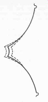
Fig. 7. Controlled flexure. At high frequencies the central areas of
a curved cone move independently of the rest. The higher the frequency
the smaller the active area. This thus serves as an effective high frequency
radiator.
Cone Velocity and Radiation Resistance
The effect of cone inertia is to limit its acceleration, just as a heavy lorry which has considerable inertia, cannot get away so quickly from the lights as a light car. As the frequency rises and the cone makes more excursions per second its speed needs to increase to maintain the same amplitude. This requires more power, but if the power is constant the speed must also be constant. So when the frequency rises, the amplitude of the cone excursions must decrease to maintain the same speed.
This means that the response diminishes as the frequency increases, an effect which without compensation would give a very poor treble reproduction.
Fortuitously, and by one of those rare quirks of the laws of physics, there is another defect in the way sound is propagated by a loudspeaker cone that almost exactly cancels the effect of the first. This is radiation resistance. At low frequencies the cone is an inefficient sound radiator. It pushes the air out of the way instead of compressing it into a sound wave.
As the frequency increases, the air does not move aside fast enough to avoid compression but offers a resistance to the cone and so produces sound. The higher the frequency up to a certain point, the greater the radiation resistance and the more efficient the air coupling to the cone. Thus the acoustic output rises and exactly compensates for the diminishing cone excursions.
The compensating effect works up to a point where the radiation resistance is at a maximum and cannot increase further. This frequency range is termed the piston region of operation. Above this the response begins to fall off because the cone excursions due to velocity effect continue to decrease.
However, cone flexure effects maintain the response further, and also the beaming effect at high frequencies increasingly concentrate the sound in front of the cone. Thus a useful response continues well above the piston region so making full-range single-unit speakers viable.
The piston region transition point is dependant on the diameter of the cone. For a flat disc radiator in a true infinite baffle, the relation between the transition frequency and the cone diameter is:
f_ 68,275 ad in which d is the cone diameter in centimeters.
Doppler Effect
Doppler effect is frequently heard when an ambulance or police car passes. The number of sound waves reaching a stationary listener in a given time is increased by the forward velocity of the vehicle as it approaches. Hence the frequency is greater and the pitch of the sound heard by the listener is higher. When the vehicle passes and recedes, the sound wave count per unit of time is then reduced by its velocity, and so the pitch drops.
The same effect can be produced by a loudspeaker cone when it is producing a high and low frequency simultaneously.
Visualize the cone oscillating rapidly at the high frequency. At the same time it is moving slowly (relative to the high frequency excursions) forward and backward to generate the low frequency.
When the cone moves forward toward the listener, the pitch of the high frequency sound is raised, and when it moves backward, the pitch is lowered. Thus the high frequency tone is modulated by the low, the effect being a form of frequency modulation distortion.
The modulation is proportional to the speed of the cone at its low frequency excursion, just as the doppler pitch change of the ambulance siren is proportional to the vehicle's speed. If it travelled at walking pace the difference would be too minute to be detected.
So the distortion is greatest when the cone is making large bass excursions. Now as small cones must make larger excursions than large ones to generate the same acoustic power, it follows that small cones generate more f.m. distortion. When two different sized speakers are compared, the distortion increase in the smaller one is proportional to the square of the decrease in cone diameter from the larger unit. It is at a maximum for a listener on axis but decreases with the off-axis angle.
Doppler distortion is one argument in favor of having separate drivers for the bass and treble, although in theory it can still occur between widely separated frequencies within the pass band of each unit. Listening tests though, suggest that a 20 mm cone excursion is the lower limit below which modulation cannot be detected. This is a very large excursion which would be unlikely to be reached in domestic circumstances by reasonably sensitive speakers, although it could be exceeded in high power disco set-ups. At normal listening levels the doppler effect is rather like that of an ambulance travelling at walking-pace. Really then, its effect can be discounted and need not deter anyone wishing to use single full-range speakers instead of multiple units.
The Tweeter
Turning now to the tweeter, we find that it uses the same general principle as the bass speakers, although there are some differences apart from size. One noticeable feature is that unlike the bass speaker the back of the unit is totally enclosed.
This is to prevent the tweeter cone being affected by the large air pressure differences that are generated inside the cabinet by the bass speaker.
To achieve a high rigidity-to-density ratio and so avoid buckling and other cone deformations that can be produced by the high accelerations it can encounter, metal such as aluminum and beryllium has been used as a cone material.
This increases the sound velocity within the material which pushes the first break-up mode higher up the frequency scale.
However, rigidity can also produce a problem in that there is little or no flexure, so the radiation resistance falls off at an earlier point than with a less rigid cone and the treble response suffers accordingly. The use of metal-coned tweeters thus tends to be confined to narrow bandwidths, with super-tweeters covering the highest octave or so. Other than these, paper with a high kapok content and mica are the principal materials.
Another feature with many tweeters is that the conventional cone is reversed to form a dome. This overcomes some of the problems associated with cones and gives a wider angle of dispersion. While high-frequency beaming can be useful to a limited extent to concentrate the high frequencies in front of a full-range speaker and so enhance its treble response, if too pronounced with a tweeter, it results in an unpleasant over-emphasis of treble for those listening on axis, and a deficiency of treble for those not directly in front. A dome tends to disperse high frequencies and reduce beaming.
As mentioned earlier, temperature rise can be a problem as the small size does not lend itself to rapid dissipation of heat.
Liquid cooling of the air gap with colloidal ferromagnetic fluid which also helps to concentrate the magnetic flux is employed with some models.
Phasing
Whenever more than one speaker is to be operated in the same air space it is essential that correct phasing be observed. Sound waves consist of alternate compression and rarefied regions of air that spread out at high speed (1,090 ft, 332 m per second at 0°C at sea level) from the source. If there are two loudspeakers working close together, and they are not in phase, the cone of one moves backward while that of the other moves forward.
The compression wave produced by the one will therefore merge with the rarefaction generated by the other, and the two will cancel. Cancellation is greater at wavelengths longer than the distance between the speakers which means that the bass suffers most. With speakers that are very close such as on the same baffle, frequencies right up to the treble range are cancelled. When constructing speakers having multiple drivers, it is therefore very important to ensure that they are wired correctly.
To enable this to be done, one of the speaker terminals is marked with a plus sign or a red spot. All such must be connected to the same terminal of the amplifier. In the case of a stereo pair, they must be connected with similar terminals going to similar contacts on the amplifier output sockets.
If a loudspeaker is to be used with unmarked terminals, they can be identified by one of two methods. One-way is to connect it to an amplifier together with another speaker that is marked, and stand them side by side. Play some music with a good bass content, then reverse the connections to one speaker.
Connected one way, the music will sound full with plenty of bass, but the other way it will sound thin with the bass lacking.
When the bass is present they are in-phase and the terminals can be marked the same as the known speaker. If both speakers are unmarked but they are to be used together, an arbitrary marking can be made of both sets of terminals to ensure that like terminals will be connected to the same side of the amplifier.
The other method does not need another speaker or amplifier, but requires a 6- or 9-volt dry battery. Connect a pair of leads to the battery, and the other end of one lead to one terminal of the speaker. Rest your fingers lightly on the front of the speaker cone near the center, and momentarily touch the free end of the second lead to the unconnected speaker terminal. The cone will be felt to jump slightly either forward or backward. If it jumps forward, the positive pole of the battery is connected to the plus terminal which should thus be marked. If it moves backward toward the magnet, the negative battery pole is connected to the speaker plus terminal (Fig. 8).
If the speaker is not very sensitive or the battery is low, it may be difficult to determine whether the cone moved forward or backward. If in doubt reverse the connections and try again.
The difference in direction of movement should be now apparent by comparison. Cables used to connect speakers should always have some means of identifying the conductors so that the speakers can be correctly phased.
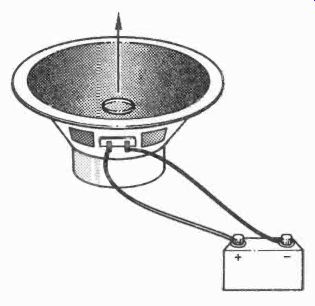
Fig. 8. Battery phasing of an unmarked loudspeaker. The terminal which
is connected to the battery positive is the '+' or red spot when the cone
moves upward. Contact to battery should be only momentary.