Although the moving coil driver has reigned supreme as the principal sound reproducer for many decades, it has had several challengers. These have been developed to avoid some of the problems associated with the moving coil unit, but they have had their own drawbacks. These are some of the main ones.
Electrostatic Speakers
The moving member that produces the sound pressure waves in an electrostatic speaker is a thin plastic diaphragm that is coated with a conductive deposit. The basic unit has a rigid metal back plate from which the diaphragm is separated by a thin layer of air. When a high voltage is applied across the diaphragm and plate, there is a mutual electrostatic attraction between them which pulls the diaphragm taut toward the plate.
The attraction is dependant on the voltage applied, so if the voltage is made to vary in sympathy with the signal, the diaphragm moves accordingly and so generates sound pressure waves at its front surface.
One attraction of this system is that the diaphragm is driven over its whole surface by the applied voltage, unlike the moving coil cone which is driven only from its apex. Thus the whole surface moves in unison without any of the buckling or other spurious distortion-producing motions suffered by the cone. This gives rise to another major advantage. As it is wholly under the control of the applied signal, it does not need to be made rigid, which in turn means that it can be extremely light. Having thereby a very small mass, it responds readily to sudden signal changes and so is an excellent reproducer of high frequencies and transients.
The first snag is that both positive and negative half-cycles of an applied signal cause movement of the diaphragm in the same direction, toward the back plate, because attraction is not dependant on polarity. This produces an effect termed frequency doubling as the diaphragm moves backwards and forwards twice for each cycle. Fortunately this one is easily overcome. The a.c. signal is superimposed on a fixed d.c. potential which serves as a bias. Thus the signal adds and subtracts from the steady bias voltage on alternate half-cycles, and the diaphragm moves accordingly.
Push-Pull
The electrostatic charge depends not only on the applied voltage but also on the spacing between the two members. The closer they are, the greater the attraction. This poses another problem. As the diaphragm move backwards and forwards the spacing also varies. So the attraction depends on the position of the diaphragm at any instant. The signal has a greater influence when the gap is narrow than when it is wide, which is at the peak of one half-cycle, so the response is non-linear, and amplitude distortion results. Especially is this the case for the lower frequencies at which diaphragm excursion is at its greatest.
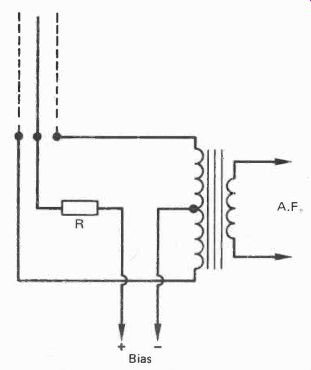
Here again there is a neat answer. It is to employ two plates that are acoustically transparent such as a mesh, one on either side of the diaphragm. The signal is split in phase into two of opposite polarity, usually by means of a transformer secondary winding with a center-tap. These are applied along with the d.c. bias between the diaphragm and each of the rigid plates. So at each half-cycle, the attraction hence the distance between the diaphragm and one plate is increased, while that to the other is diminished. The reduced force on one side is thereby balanced by the increased force on the other. This is known as push-pull system, a principle also used in amplifier output stages. Harmonic distortion is thereby cancelled out.
Charge Migration
There is still another problem. The device is really a large capacitor and so behaves as such. Like any capacitor, current flows in when a voltage is applied and charges it up to a limit that depends on the value of the capacitance. If the capacitance varies, current flows in and out in sympathy with the variation. Capacitance depends on the spacing between the elements of any capacitor. So, when the diaphragm moves and the spacing varies, so does the capacitances, and thus also the stored charge, Now attraction between the diaphragm and the fixed plates depends not only on the applied voltage and the spacing, but also on the electrical charge that is stored in it. If this varies, so does the attraction and thereby the diaphragm excursion.
Therefore, the diaphragm motion is not dependant totally on the applied signal, but also the charge flowing in and out of the device, which thereby introduces distortion. Again there is a simple solution. It consists of including a high value series resistor in the bias supply (Fig. 9). The time constant of the resistor/capacitance combination is very long compared to the lowest frequency to be reproduced, it is in fact a matter of ...

Fig. 9. Electrostatic push-pull circuit.
... minutes rather than seconds. This permits very little charge to flow in and out during the diaphragm excursions, so the applied force is due solely to the signal voltage.
There is yet a further snag though. If one part of the diaphragm becomes closer to one of the plates than another, the local capacitance of that area increases and the charge present will flow to that point from an adjacent area that is not so close. The attraction at that point thus becomes greater producing a further movement toward the plate.
So the diaphragm fails to move equally over its whole area, and any minor differences quickly multiply. The solution to this problem is similar to that of the last one, introduce high resistance to limit the flow of current from one part of the diaphragm to another. This is achieved by making the conductive coating highly resistive, as it does not have to be a good conductor to function. Typically, the coating is given one conductive atom to ten million non-conductive ones and has a measured resistance of hundreds of megohms.
Frequency Response Anomalies
The radiating pattern of the electrostatic speaker is that of a doublet, that is it radiates equally from the front and from the back. It is thus similar to a moving coil speaker on a flat baffle. As a compression wave is generated by one side at the same time as a rarefaction wave is radiated by the other, cancellation occurs when the two meet at the edge. This occurs at all wavelengths longer than the radius of the doublet, so the response at such wavelengths which correspond to the lower frequencies, is poor.
To minimize this the speaker can be made very large, or it can be placed in a cabinet. The latter course is universally used for moving coil drivers, but is impractical for electrostatic units because the high pressures built up in a cabinet would greatly influence the movement of the very light diaphragm.
To produce a reasonable bass response then, the speaker must be large. However, this can have an adverse effect on the treble response. The reason for this is that while all sound produced on-axis is coherent, arriving at the listener at the same time this is not so at any point off-axis. If the difference in distance from one point on the diaphragm to the listener, and another point on the diaphragm to the listener is equal to half a wavelength, cancellation of that frequency will occur.
With a large speaker, many such points will occur at different wavelengths across the width of the diaphragm as the listener moves off-axis. The shorter the wavelength the greater the number of points within the width. So, the high frequency response suffers at all off-axis positions.
The early Quad electrostatic speakers minimized this effect by using three units, a narrow center one to handle the high frequencies, and two bass ones on either side. This required the use of a crossover circuit to separate the treble from the bass and added to the complication of the drive circuitry.
In the later models the conductive coating is divided into five concentric rings with a center and two outside segments making eight in all. These are fed from a sequential delay line so that the signal is first applied to the center, and then consecutively at 24 u-S delays with attenuation to the other sections. A spherical-fronted wave is thereby produced which simulates a point source situated some 30 cm behind the diaphragm. Such a source has a wide angle of dispersion with no cancellation effects off-axis.
Flash-over
The voltage required for polarizing an electrostatic speaker is quite high, (5.25 kV with the Quad), and the signal voltage must be of similar order. As the spacing must be kept small to obtain maximum electrostatic attraction and sensitivity, there is an ever present risk of flash-over which could damage the diaphragm. Reducing the applied voltage is not the answer as this also reduces sensitivity.
One speaker has the entire unit sealed in an inert gas which inhibits flashovers and thereby permits higher voltages and greater power output. Another (the later Quad) senses the ionization which precedes a flashover by means of an aerial running around the frame. When it is detected a triac 'crowbar' circuit is immediately activated which short circuits the amplifier output with a 1.5 ohm resistor! There is also a limiter circuit which adds audible distortion when the input signal from the amplifier exceeds 40 V. Another method of flash-over protection is to use thermoplastic coated with a conductive material on the outer surface for the rigid plates instead of metal. Thus the plate material serves as an insulator to inhibit flash-overs, although the extra spacing to the active outer coating inevitably reduces sensitivity.
We have described the electrostatic speaker and its snags at some length, for a purpose. At first glance it may appear that its low-mass diaphragm and the even drive over the entire area virtually solves the problems inherent with the moving-coil unit which it should have ousted years ago. These observations should show that while successful electrostatics have indeed been produced, they are not without drawbacks and complications. The moving-coil unit thus remains the most practical means of sound reproduction.
Orthodynamic Drivers
The Orthodynamic speaker uses a thin plastic diaphragm driven over its whole surface in a similar manner to the electrostatic, but the impelling force is electromagnetic. It thus avoids many of the problems associated with the electrostatic, one of the principal ones being the elimination of a polarizing voltage and high signal voltages with their risk of flash-over.
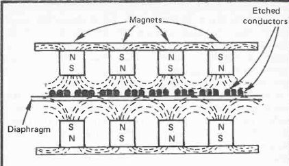
The diaphragm has a pattern of copper or aluminum conductors etched on to it in a similar manner to that of a printed circuit. Magnetic fields are set up over the diaphragm surface by either short individual bar magnets mounted on both sides perpendicularly to the surface, or by two plates of ceramic magnetic material on either side. The plates have holes over their whole area to permit the sound pressure waves to be radiated, and they have magnetized zones between the holes.
Each zone is equivalent to an individual bar magnet. (Fig.10).
The outer ends of each magnet or magnetic zone are linked with a ferrous plate or surface so that adjacent magnets are in series and thereby form a U magnet with the free poles facing the diaphragm surface. The magnetic field thereby passes from one pole, then longitudinally along the surface, and back to the adjacent opposite pole on the same side.

Fig. 10. Orthodynamic principle. Etched conductors on a plastic diaphragm
carry signal current in fields from magnets on either side.
On the opposite side of the diaphragm, the magnets are arranged so that the poles are of the same polarity as those facing them on the first side. As like poles and magnetic fields mutually repel, the fields are concentrated at the halfway point between them which is where the diaphragm is. Thus maximum field concentration is obtained at the diaphragm.
Conductor Pattern
A simple spiral or zig-zag pattern for the etched conductor cannot be used because current in adjacent runs would be travelling in opposite directions. This would produce magnetic forces impelling adjacent parts of the diaphragm in different directions. So a more complex pattern of loops that double back on themselves must be employed to ensure that all conductors lying within the same magnetic field direction carry signal current in the same direction.
The metal conductors etched onto the diaphragm must carry current and so be of greater thickness than the conductive coating of the electrostatic diaphragm. As a result the mass is greater and so the transient and treble response is not quite that of the electrostatic although it is very good. There must be reasonable air spacing between the magnets and the diaphragm to allow diaphragm excursion, so this is necessarily much greater than the small air gap between the poles of the moving-coil driver. As any air gap in a magnetic circuit introduces magnetic resistance (reluctance), the larger gap means greater magnetic losses. Hence the orthodynamic speaker is less sensitive than a moving-coil unit.
A similar problem exists to that of the electrostatic speaker regarding diaphragm size. If it is too small, bass frequencies are lacking, whereas if it is large enough to produce sufficient bass, there are cancellation effects off axis at treble frequencies. Because of this, orthodynamic speakers have been confined to tweeters or mid-range units requiring a conventional moving-coil driver for the bass.
Heil Air Motion Transformer
This device is a variation on the orthodynamic driver having an etched conductor on a plastic diaphragm that operates within applied magnetic fields, but has two main differences.
The first is that the magnetic fields are at right angles to the diaphragm instead of being in the same plane.
The second is in the nature and motion of the diaphragm itself. It is not flat but is arranged in folds like a concertina.
Instead of producing a backwards and forwards motion, the direction of the magnetic field imparts a sideways movement.
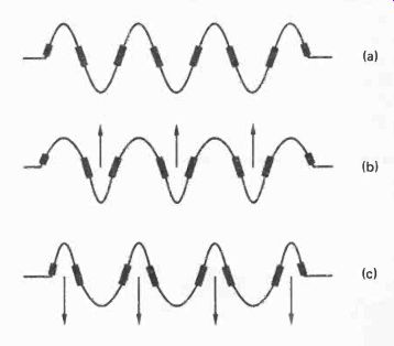
This causes the folds in the diaphragm to open and close, sucking air in and squeezing it out (Fig. 11).
Most other drivers employ a lot of energy to move a small amount of air with the result that the efficiency is low; a large amount of electrical watts is required to produce a small number of acoustic watts. Rather like driving a car along a flat road in bottom gear. The idea of the air motion transformer is to change up to a higher gear. A small movement of the diaphragm produces a much larger air motion. It is similar to the squeezing of an orange pip between the fingers, small finger movement and pressure can send the pip yards.
Here again, the problems of combining good high and low frequency response has limited the device to tweeters and mid-range units. The higher acoustic efficiency is partly offset by the lower magnetic efficiency which is inherent with the orthodynamic principle. In any case, efficiency has to be matched to that of the bass unit to achieve a tonal balance, so high efficiency in a tweeter or mid-range unit is not of itself important. Smooth response and low distortion are more so.

Fig. 11. Heil Air-Motion Transformer. The diaphragm is formed into concertina
folds (a). Alternate attraction and repulsion of conductors on adjacent
folds squeeze air alternately from each side, (b & c). Large volumes
of air are moved by small diaphragm motion.
Ribbon Tweeter
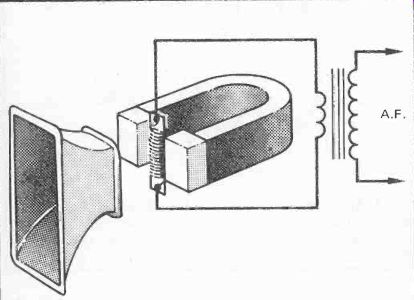
The principle of this unit is the same as a ribbon microphone in reverse. The ribbon is formed of aluminum foil which is corrugated or ribbed to allow forward and backward motion when it is suspended from its ends between powerful magnet pole pieces. It is mounted edgeways to these so that its movements it at right angles to them, and the air gap between ribbon edge and pole piece is very small.
The signal current is passed along the ribbon which sets up a magnetic field that interacts with that of the magnets and so produces a force on the ribbon. The electrodynamic principle is the same as that of the moving coil, and in fact it can be considered as a moving coil speaker with a single turn. Being very light the ribbon responds well to high frequencies, and as it is impelled over its whole area it is free from the distortions inherent with a cone reproducer. (Fig. 12).

Fig. 12. Ribbon tweeter. A corrugated ribbon is suspended between the
pole pieces of a powerful magnet. Audio signal is applied through a
step-down transformer. A horn couples the ribbon to the free air.
Its small area precludes its use for bass or even mid-frequencies. A wider ribbon would increase the gap between the magnetic pole pieces and so weaken the field resulting in low efficiency; so there is a limit to its size. Even at high frequencies it efficiency is not great so it usually has a horn mounted in front to provide a more effective air coupling.
The horn also restricts the lower frequency range as its size governs the lowest frequency at which it is effective, and there is a practical limit to its size. Coloration occurs at the frequency where horn efficiency falls off, so the tweeter is usually operated well above that point in conjunction with a crossover network and bass and mid-range speakers.
The impedance of the ribbon is very low, just a fraction of an ohm, so coupling to the amplifier output must be via a matching transformer. This must be carefully designed to minimize frequency and other forms of distortion otherwise the advantage of the ribbon's low distortion would be lost.
Plasma Tweeter
This is a rather exotic device not often encountered, but with interesting features. 'The moving part' which generates the sound is the lightest one of all, an electric arc! When an arc is set up between a pair of electrical conductors local heat of high temperature is generated which causes a violent expansion of the air in the immediate vicinity. Sound is thereby produced, a familiar example being the clap of thunder resulting from a lightning stroke.
If the arc is modulated with an audio signal its intensity varies accordingly and so does the heat produced. Air expansion likewise varies and thereby also the sound pressure wave. So sound is generated in sympathy with the modulation.
A number of tweeters have been produced over a period of many years using this or a similar principle. One recent one consists of a sphere of a fine mesh having at its center a fine needle electrode. A high radio-frequency electrical potential at 27 MHz which is derived from a crystal oscillator, is applied between the needle and the sphere. Positive and negative ions are produced alternately, and the air in the vicinity of this corona discharge is heated to a temperature of 1,500°C.
The audio signal is amplitude modulated on the r.f., and so the intensity of the corona changes, also varying the heat around the 1,500°C mean. A spherical sound wave which is totally in phase, is thus radiated around the device at all angles. There are thus no frequency response differences at any off-axis position.
As it is the air itself that initiates the sound wave, there are no low-efficiency coupling problems, furthermore there are no resonance or coloration effects caused by physical moving parts. The frequency response extends from 4.5- 150 kHz, which is considerably beyond the audio range. Total harmonic distortion is less than 1% at any part of its frequency range, and the maximum output is 95 dB at 1 meter.
That high temperature may sound dangerous, but actually it is not. The amount of heat is quite small and it is not even sufficient to heat the sphere to any noticeable extent.
Temperature is not a measure of the amount of heat. A teaspoonful of boiling water contains less heat than a bucketful at hand temperature.
A filter is included with the unit so that it can be connected directly across existing speakers to extend the treble response.
Its range is excessive, but the all round in-phase feature as well as the low coloration is very attractive. If a full range version that would produce bass frequencies could be devised, this could be the ultimate loudspeaker. Its main drawback at present is the price.
Piezo Tweeter
Coming now to a more practical proposition, especially for the home constructor, we now consider the piezo tweeter. There are a number of substances that change dimensions if they are subject to an applied voltage, or generate a potential if subject to mechanical stress. A naturally occurring one is Rochelle salt which was once used for audio devices such as microphones and gramophone pickups. It is fragile though, and its performance is subject to humidity changes. Now, manufactured ceramic materials such as lead zirconate titinate have replaced it, as these are more stable and robust.
The simplest device is termed a monomorph which consists of a single slice of the ceramic, but the movement produced by the voltage-induced dimensional change is very small.
An improvement is to cement two slices together to form a bimorph. The combination is secured at one end and a voltage is applied in such a manner that one slice shrinks while the other lengthens. This produces a bending action with a sideways displacement of the free end. Movement is thus much greater than with a single slice. The bimorph is of itself too small to produce much sound as the movement is less than most other types of tweeter. It is therefore linked to a cone or coupled to the air via a horn like the ribbon tweeter.
The device is capacitive which means that there is no direct resistance across it and the impedance consists mostly of capacitive reactance. The practical effect of this is that the impedance is very high at low frequencies dropping to around 1,000 ohm at 1 kHz, from which is falls smoothly to 30 ft at 40 kHz. A consequence of this is that it can be connected directly across a bass speaker without the need of a crossover network.
This is a major advantage as the crossover circuit is the source of many evils as we shall see in a later section.
Having no coil appended to its apex like the moving coil tweeter, the cone has a much lower mass. It therefore has a superior transient response and a frequency range up to 40 kHz. Its response is smooth, typically within ±2 dB from 3-30 kHz. Distortion is around 0.5% over most of its range rising to just over 1% at 1 kHz. The unit will accept continuous signals of 15 volts, which is 28 watts into 8 ohm or intermittent music peaks of 30 volts, which is 110 watts into 8 Si It thus has ample power handling capacity. One maker who has a range of piezo tweeters is Motorola, and these are probably the best choice of tweeter for the home constructor.