By T. A. O. Gross
MENTION timing circuits, and most people tend to think of the ubiquitous 555 IC. While the 555 is excellent for most timing applications, other devices are worthy of consideration.
These are the CMOS CD4060A and SCL4060AB 14-stage ripple-carry binary counters from RCA and Solid State Scientific, respectively.
Among other advantages, the 4060-series devices can be less expensive to implement in a given application because they require less critical and less expensive resistors and capacitors. A second advantage is that 4060-series devices can deliver a number of output frequencies from the same RC components; the 555 delivers only one.
Technical Details. In a 555 timer circuit, external frequency-determining resistor and capacitor values must be selected to produce the desired oscillator frequency directly. As a result, in many cases where relatively long time constants (low frequencies) are desired, the RC product requires the use of bulky, expensive electrolytic capacitors with, often, inaccurate values and high losses.
Devices of the 4060-series use oscillator frequencies much higher than what is required at the output. The oscillator frequency goes through a 14-stage binary counter that divides it by as much as 16,384 (214) before it is used as the final timing frequency.
Using a much higher oscillator frequency than the 555 timer to obtain the same timing frequency the 4060 has a correspondingly smaller RC product. Hence, there is no need to use inaccurate and unstable electrolytic capacitors or humidity-sensitive, very-high-value resistors.
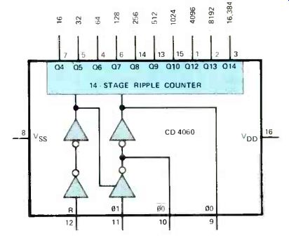
Fig 1. Internal schematic arrangement of the RCA CD4060 timer integrated
circuit.
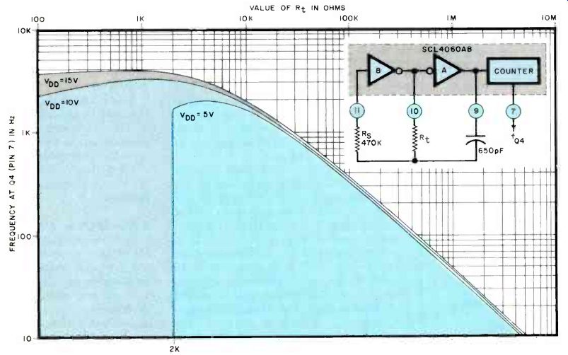
Fig. 2. With low values of timing resistor, 19, the frequency of the
circuit can vary with applied dc operating voltage.
While the CD4060A and SCL4060AB are interchangeable in most cases, the two are different. In the CD device, the oscillator is keyed by the reset input, whereas in the SCL device, the reset operates on the dividers, leaving the oscillator in continuous operation.
Basic internal logic of the CD4060A is shown in Fig. 1. Two of the four inverters serve as the active elements of the internal oscillator whose output is passed through the 14-stage ripple-carry binary counter. Oscillator frequency is set by an RC network, or an external crystal oscillator can be connected to pin 9 to eliminate the need for the internal oscillator. When the internal oscillator is used, the input at pin 12 is provided to reset the counter to zero and disable the oscillator.
It is not necessary to use all 14 stages of division. As shown in Fig. 1, you can select division factors of 16, 32, 64, 128, 256, 512, 1,024, 4,096, 8,192, or 16,384, simply by picking off the output from the appropriate pin of the IC. Timing resistance values of 4060-series devices should not be less than 10,000 ohms to avoid changes in frequency with changes in applied dc operating voltages.
As can be seen in Fig. 2, the frequency/resistance function reverses at about 4500 ohms with a 5-volt supply and at 1300 ohms using 10 volts.
The frequency calculation formula for the 4060 given in manufacturer application notes is F = 1/(2.2R,C,), where R, and C, are the values of the timing resistor and capacitor. This formula assumes Voo is 10 volts, C, is greater than 100 pF; R, is greater than 1000 ohms, and RS is larger than 10 times R,. (RS is the external stabilizing resistor, as shown in the inset schematic diagram in Fig. 2.) In this author's experience, this formula is accurate only when R, is greater than 50,000 ohms.
With values less than 50,000 ohms, observed frequency was lower than predicted by the formula.
Data given in Fig. 2 was obtained at the pin-7 (=16) output from an SCL4060AB. With time delays of more than a few hours, it was determined that use of R5 is not necessary.
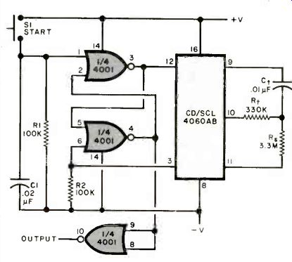
Fig. 3. With the values shown, this circuit has a one-minute delay period.
The output strobe goes high after timeout.
Practical Timer. Shown schematically in Fig. 3 is the circuit for a practical 1-minute timer built around a 4060-series device. A 330,000-ohm resistor and 0.01-µF capacitor are doing a job that would require a 60-megohm/microfarad RC product in a 555 circuit.
Momentary closure of START switch SI causes the set-reset flip-flop made up from two gates in a 4001 quad 2-input NAND IC to produce a high output at pin 12 of the 4060. After the timing interval (oscillator frequency) determined by R, and C,, pin 3 of the 4060 goes low and toggles the flip-flop to stop the counter. At the same time, the output of the bottom 4001 gate, held low during the timing interval, goes high.
(Since the 4001 contains four on-chip gates, the fourth gate can be parallel with the output stage to provide more driving current for an external circuit.) Much longer timing intervals can be obtained by cascading the pin-3 output of the 4060 with a 4020, a 14-stage counter that is similar to the 4060 but lacks the internal oscillator.
Capacitor C1 and resistor R1 improve the circuit's immunity to noise and are optional.
Summing Up. Once you start working with 4060-series devices, you will probably think of them as often as you do the 555 for your timing applications. Their easy implementation into circuit designs and reduced demands on frequency-determining resistors and capacitors make them particularly attractive where costs must be kept down and hardware space is at a premium. And they offer a number of different output frequencies from a given RC network that gives them an important advantage over single-frequency-only timing devices.
Source: Computers and Electronics--Experimenter's Handbook (1984)
Also see: Simple Memory Addition For Training Converters