BY RALPH TENNY
How to check out and use modules that clutter your junk box.
AC ADAPTERS for operating portable equipment such as radios, tape decks, calculators, or shavers from the power line instead of the usual batteries represent an often unrecognized resource for the electronics experimenter. The chassis for a project can often be made smaller and cheaper if one of these devices is used to supply operating power. And if small children are involved in any way with the project, the isolation from the power line provided by the adapter can be a safety factor. In addition, one adapter can power several projects if they are not all in use at once. Best of all, you probably have several of these devices left over from old, discarded appliances.
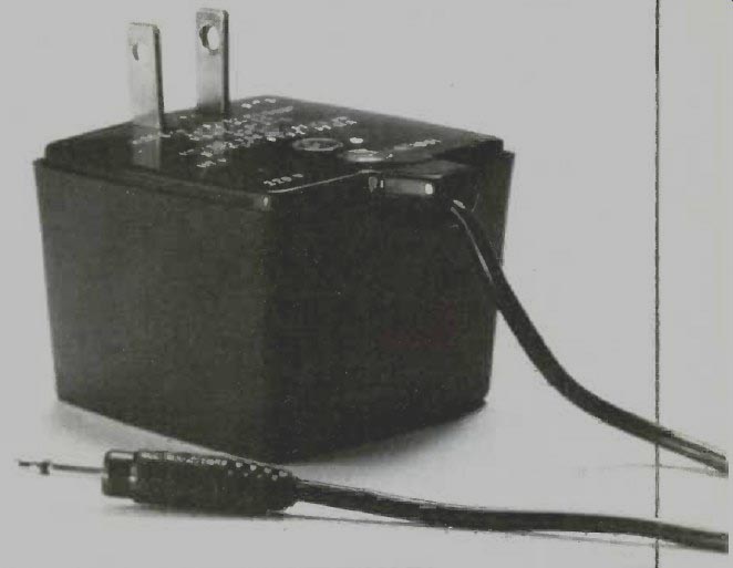
Types of Units. Since adapters are designed to reduce the nominal 117 volts at the wall socket to a lower voltage, all of them contain a small low-power transformer. There are two basic outputs from these devices; ac only or some form of dc. To identify the output, read the label on the case. If the label cannot be read, an oscilloscope across the output with a light resistive load (1 to 5 kO) will quickly identify it. An ac-only device will display a line-frequency sine wave, while a dc-output device that incorporates filtering will show a dc level with a small amount of ripple. If there is just a rectifier with no filtering, a line-frequency half sine indicates half-wave rectification while a series of half sines at twice the line frequency indicates full-wave rectification.
Testing. The setup used for testing ac and dc output adapters is shown in Fig. 1. The only practical difference between the two types is that a rectifier is used with the ac device.
With the load resistor disconnected, the supply will deliver its maximum dc voltage (1.41 times the rms value of the transformer output voltage) Construct a graph with voltage on the vertical axis and current on the horizontal axis. The upper end of the voltage axis is marked with the maximum (unloaded) voltage from the test circuit; from that point to the bottom (where this line joins the current axis) divide the voltage axis evenly into volts and parts of volts.
Ohm's Law (R=E/I) is used to determine the value of load resistor used.
If, for example, the dc output is 15 volts, a 15,000-ohm resistor will draw 1 mA, a 1500-ohm resistor 10 mA, and a 150-ohm resistor 100 mA. If we wanted to start the current plot at, say, slightly under 10 mA, then a potentiometer (5-watt) having a value of 2000 to 2500 ohms will be required. To avoid burning out the module when the pot is set toward its low end, connect a 150-ohm, 2-watt resistor in series with the potentiometer to limit current flow to 100 mA. This latter resistor can be reduced if the supply proves capable of delivering more than 100 mA. Adjust the potentiometer until the current meter indicates 10 mA. Observing both meters, plot the voltage and current on the graph. Reduce the potentiometer resistance until 15 mA is flowing. Plot the voltage and current again.
Repeat these steps until you have sufficient data to construct a curve like that in Fig. 2. During these tests, make sure that the transformer does not overheat (though it may feel warm to the touch), indicating excessive current drain.
An oscilloscope connected across the output of a dc supply may show considerable ripple, particularly if the supply uses a half-wave rectifier or is heavily loaded. To reduce this ripple, add more filter capacitance. As a general rule of thumb, doubling the capacitance will halve the ripple.
The graph you have drawn will give a close estimate of output voltage at any given load current. In addition, it allows you to determine regulation (the degree to which the voltage varies with load). This is expressed as the percentage of the open-circuit voltage measured with maximum output current. Thus, the curve shown in Fig. 2 indicates regulation of 48%. The higher the regulation, the better the supply.
Before an adapter is used to power a project, it should be tested under load for an hour or more. If the exterior case gets too hot to touch comfortably, a hazard may exist, and a higher capacity adapter should be used.
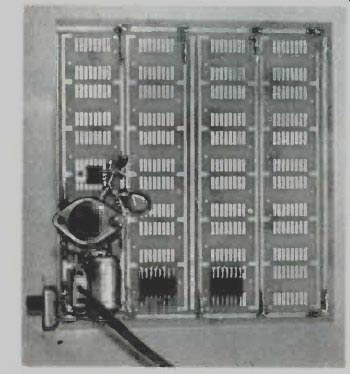
--------- Rectifier and regulator on prototype board.
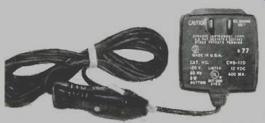
------- Ac adapter used as a trickle charger for automotive battery.
AC Circuits. Four typical rectifier circuits for use with ac-only adapters are shown in Fig. 3. A full-wave rectifier like that in Fig. 3A can be had as an encapsulated module or synthesized from discrete silicon diodes. A filter capacitor is added to smooth the output and produce useful dc. For low-current applications where cost is a big factor, a half-wave rectifier circuit can be used.
This is shown in Fig. 3B. The voltage doubler (Fig. 3C) and tripler (Fig. 3D) will deliver two and three times, respectively, the open-circuit voltage of a half-wave supply but with only small currents. In addition, they have very poor voltage regulation and excessive ripple unless very large valued filter capacitors are used.
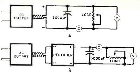
Fig. 1. The difference between the test circuit for an ac and dc adapter
is the rectifier required by the ac version.
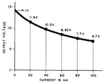
Fig. 2. A typical load regulation curve used to evaluate an ac adapter.
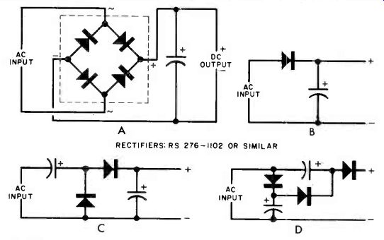
Fig. 3. Four circuits for an ac adapter. Full-wave rectifier (A), half-wave
(B), half-wave voltage doubler (C), and voltage tripler (D).
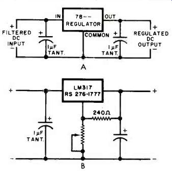
Fig. 4. Three-terminal regulator at (A) delivers a fixed voltage while
the circuit shown in (B) is adjustable and regulated.
DC Circuits. These types of adapters usually have some internal filtering, but for good results require about 1000-µF of external filtering. To improve voltage stability under load, an external regulator module can be added. The most convenient type of regulator to use is a three-terminal device such as the 7805, 7809, or 7812. These accept up to 35 volts input and deliver 5, 9, and 12 volts respectively. A typical circuit is shown in Fig. 4A. This circuit is ideal for noncritical, low-power applications, and is inexpensive. Three-terminal regulators are very rugged, and have internal circuits to protect them from overheating and overload. Keep in mind that the input voltage to the regulator must be at least 2.5 volts higher than the desired output voltage with maximum current drawn from the supply.
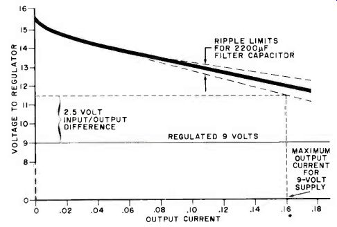
Fig. 5. Graphical operation of a 9-volt regulator showing how ripple
affects delivered current.
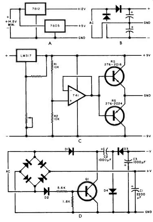
Fig. 6. Various methods of generating positive and negative voltages
from a single power source.
The graph of Fig. 5 illustrates a dc source applied to a 9-volt regulator with the ripple voltage added. Note that as the output current increases, the output voltage comes closer to the desired regulated voltage. At some current, the regulator input voltage will intersect the lower edge of the ripple band. This then becomes the maximum allowable output current for this particular combination. This curve illustrates the need for load testing a finished supply.
By using a "third generation" three-terminal regulator such as that shown in Fig. 4B, a variable regulated voltage from about 1.2 volts to the input voltage minus 2.5 volts can be built.
Multi Voltages. Circuits requiring more than one dc voltage are shown in Fig. 6. For a dc adapter, the simplest approach is Fig. 6A. This circuit delivers 12 and 5 volts, both regulated. An ac adapter can use the circuit shown in Fig. 6B to deliver both a positive and negative voltage. If desired, a 7905 can be used in the negative line to deliver regulated-5 V, while a 7805 in the positive line delivers regulated +5 V. The circuit in Fig. 6C can deliver both positive and negative voltages if the output of the dc adapter is about two V higher than the sum of the two output voltages. The LM317 is set to the sum of the two voltages, while the 741 op amp forces the two transistors to sink current from both loads. This creates a common line that is treated as the circuit ground.
This circuit can be used to create positive and negative voltages of equal or unequal magnitude, depending on the ratio of RI to R2. Both voltages will be as well regulated as the output from the regulator.
A negative voltage may be generated from a positive supply by a circuit called a "charge pump" as shown in Fig. 6D. This circuit uses alternate cycles of the transformer voltage to charge C2 via DI. The other half cycle, selected by D2, turns on Ql. When QI is turned on, the charge on C2 is dumped via D3 into C3, creating a negative voltage. With the values shown, this circuit has about 30% regulation.
A perusal of the many books covering power supplies will show a number of other circuits that can be adapted for use with ac and dc output power line adapters. With this information, it is possible to salvage most of those previously useless ac and dc adapters.
Source: Computers and Electronics--Experimenter's Handbook (1984)
Also see: High-Speed Electronic Fuse