"Blows" within microseconds to protect sensitive components
BY CHARLES M. LENNY AND CHESTER DAVENPORT
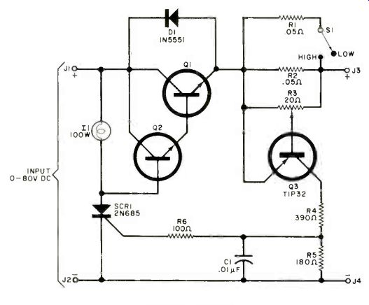
FUSES, in many cases, blow too slowly to prevent damage in solid-state circuits. Power transistors, which are prone to thermal runaway when passing excessive currents, are especially vulnerable to slow-opening fuses. The electronic "fuse" shown in the schematic is a basic crow-bar circuit that operates in a hundred microseconds or so-more than fast enough to save low-power transistors-and can safely handle load currents up to 60 amperes.
How It Works. When an overcurrent triggers SCR1 into conduction, base drive is diverted from series-pass transistors Q1 and Q2, which cut off and stop the flow of current to the load. Incandescent lamp II has about a 10-ohm resistance when cold, and drops very little voltage. When SCR1 fires, the lamp glows, and the filament resistance increases to about 100 ohms, minimizing the load on SCR1 and acting as an indicator to show that the circuit has tripped.
Potentiometer R3 establishes the desired trip current. When the current passing through R2 (and R1 when S1 is set to HI), exceeds the desired limit, transistor Q3 turns on.
The resulting positive voltage generated across RS turns on SCR1. Resistor R6 limits the SCR gate current to a safe value. Diode D1 permits operating the electronic fuse with an inductive load, removing any probability of punch-through of Q1 or Q2.
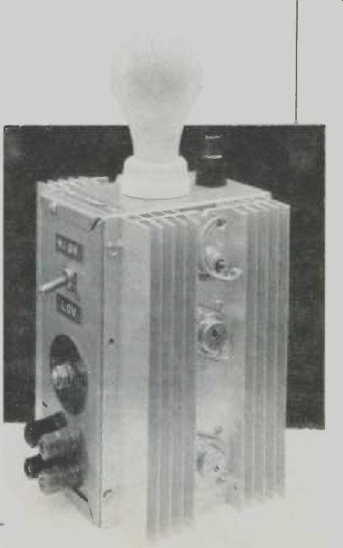
Construction. At 60 amperes, resistors R1 and R2 can dissipate 45 watts each and should be provided with suitable heat sinking. A similar heat sink should be used for Q1 , Q2 and SCR1. These two heat sinks should be mounted on two exterior sides of the selected chassis. A socket for L1 can be mounted on top of the chassis. Input and output power connectors S1 , and R3 can be mounted on an empty side as desired. The Solitron SDT96306 can handle 70 amperes at 325 volts. A 2N3055 that can handle 15 amperes at 60 volts is an acceptable substitute.
Calibration of R3 is performed by using various resistive loads to draw specific currents, with R3 adjusted so that the lamp glows when the specific current is reached. A dial plate on R3 is used to identify the calibration points. Remember that the trip current must be within the pass transistor's rating.
Since the SCR is powered by dc, once it fires it will remain in the conductive state until the applied dc voltage is removed. This can be done either by installing a series switch in either of the supply leads or by turning off the driving power supply.
PARTS LIST
C1--0.01-µF disc capacitor
D1--1N5551 diode
J1 through J4--5-way binding post, color coded
I1--100-W incandescent lamp
Q1, Q2--SDT96306 (70 amperes) 2N3055 (15 amperes)
Q3--TIP32 or any silicon transistor
R1, R2--0.05-Ohm, 50-W resistor
R3--20-Ohm, 5-W potentiometer
R4--390-Ohm, 10-W resistor
R5--180-Ohm, 1-W resistor
R6--100-Ohm, 1/2-W resistor
S1--Spat switch or SCR1-2N685 or similar SCR
Misc.--Suitable heat sinks (2) , socket for I1, enclosure, terminal strips, mounting hardware.
Source: Computers and Electronics--Experimenter's Handbook (1984)
Also see: Do-It-Yourself Logic Chips
Audio Time Delay System A Low-Cost, Analog Audio Delay Line