BY I. QUEEN
Low-cost op-amp system can measure solar-cell output and currents in other low-level circuits.
IF YOU PLAN to measure the output of a solar cell under low-light conditions, to work with micro-power ICs, or otherwise experiment with weak-current circuits, you'll need a sensitive current meter. The Sensitive µ Meter presented here will allow you to measure direct currents as small as a fraction of a microampere. Moreover, it is not subject to the disadvantages associated with standard panel micro-ammeters-high cost, fragile movements, and relatively high internal resistance.
The project employs an operational amplifier to increase the sensitivity and effectively decrease the input impedance of a moderately priced, readily available 0-to-50 microammeter. It has three switch-selected scales; 0 to 0.5 u A; 0 to 5 uA; and 0 to 50 uA. The circuit can be powered by a supply furnishing as little as ±2 or +4 V, and can be constructed for about $15.
Circuit Operation. A simple circuit for current-measuring applications is shown in Fig. 1. When an input current / is applied to the inverting input of the op amp, an inverted output signal is generated by the op amp. If the gain of the operational amplifier is very high, we can consider that the entire input current flows through feedback resistor R. An output voltmeter M, which is calibrated in terms of I, measures the product IR. The voltage drop across the operational amplifier is practically zero (the output voltage divided by the op amp's open-loop gain). The schematic of the Sensitive p. Meter is shown in Fig. 2. Switch S2 selects the range and determines the feedback resistance of the stage. When the switch is in its center (off) position, the feedback resistance is R3, one megohm. An input current of 0.5 p. A will cause the output of the op amp to be 0.5 volt above ground when only R3 is in the feedback loop.
This output voltage will cause full-scale deflection of 0-to-50-icroammeter M1 if the effective resistance between the output terminal of the operational amplifier and the negative terminal of the meter is 10,000 ohms. The internal resistance of the meter specified in the parts list is 1620 ohms, so the balance of the required resistance is supplied by R4. This trimmer potentiometer is adjusted for full-scale deflection of the meter movement when the op amp output is at +0.5 volt.
The project is most sensitive when S2 is in its center (off) position and the feedback resistance is one megohm. In this operating mode, full-scale deflection of the meter corresponds to an input current of 0.5 p. A. Higher-current ranges are obtained by shunting R3 with other resistors to lower the overall feedback resistance. This is accomplished by placing S2 in one of its two other positions. When the range switch is placed in its 5µA position, the parallel combination of R1 and R3 causes the meter to deflect to full scale if the input current is five microamperes. Similarly, placing S2 in its 50 µ A position shunts R3 with R2 and causes full-scale deflection of the meter movement when an input current of fifty microamperes exists.
Two shorting switches are included in the circuit. Switch S1 shorts the input of the project. It is used in conjunction with potentiometer R5 to zero the meter movement. The other switch (S3) is used to short the terminals of M1 when the meter is not being used. This minimizes mechanical shocks to the meter movement when the project is being transported. Diodes D1 and D2 protect the project from excessive input voltages. Jack J2 provides access to M1 so that the meter can be used in isolation from the rest of the project.
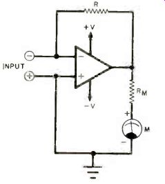
Fig. 1. Schematic of simple current-measuring circuit.
-------------------
PARTS LIST
C1--0.1µF disc ceramic
D1, D2--1N914 diode
IC1--LM308N operational amplifier
J1--Open-circuit miniature phone jack
J2--Closed-circuit subminiature phone jack
J3--Phono jack (must be insulated from project enclosure)
M1--0-to-50µ A meter movement (Radio Shack No. 22-051 or equivalent)
The following are 1/4-watt, 5%-tolerance carbon-composition fixed resistors, unless otherwise specified:
R1--110,000 ohms (can be a series connection of 100,000 ohms and 10,000 ohms)
R2--10,000 ohms
R3--1 megohm
R4--10,000-ohm, linear-taper trimmer potentiometer
R5--50,000-ohm linear-taper potentiometer
R6--2700 ohms
R7--10 megohms
S1, S3--Spst toggle switch
S2--Spdt toggle switch with center-off position
Misc.--Suitable enclosure, perforated or printed circuit board, IC socket, circuit board spacers, machine hardware, control knob, hookup wire, solder, etc.
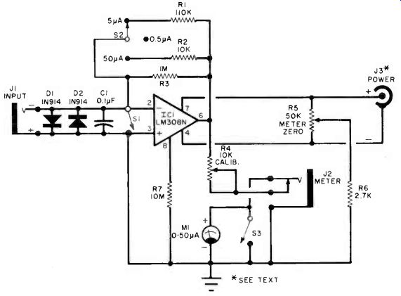
Fig. 2. The gain of the operational amplifier and, hence, the range
of the meter are determined by the amount of resistance in the feedback
circuit.
--------------------
You might wonder why the circuit provides for a 0-to-50-microampere scale when meter movement, M1, covers this range on its own. The following exercise performed by the author will illustrate the need for such a scale. A solar cell was connected across input jack J1 and illuminated so that the Sensitive µMeter indicated a current of 50 µA. The cell was then connected to J2 and its output current measured using M1 alone. It indicated a current of 1 uA. The reason for this discrepancy between the two readings is that Ml presents a higher resistance to the solar cell when it is used independently than the project as a whole does. It is desirable to keep the internal impedance of a current-measuring instrument as low as possible. Thus, it is better to employ the project as a whole (as opposed to M1 or a similar meter alone) in the measurement of currents up to 50 µA. There is another significant advantage to the use of the Sensitive µMeter as opposed to a microammeter alone. Due to the clipping action of protective diodes D1 and D2, the maximum output voltage of the op amp on any of the three ranges is approximately 0.7 volt. This corresponds to less than a 50% overload of meter movement M1, one that is highly unlikely to cause any permanent damage to the movement. An unprotected microammeter, on the other hand, can easily be "zapped" by the inadvertent application of high current overloads, a fact to which more than one electronics experimenter can ruefully attest.
Power for the circuit is furnished by an external supply via phono jack J3.
Note that the shell of this power jack must be insulated from chassis ground. The operational amplifier specified for use as IC1 is an LM308, a precision op amp that can be used with supply voltages ranging from ±2 to ±20 volts. Accordingly, a supply capable of furnishing bipolar voltages within these extremes (or a single-ended one rated at 4 to 40 V) should be employed to power the Sensitive µ Meter. Potentiometer R5 is connected across the supply to allow zeroing of the meter movement under no-input conditions (S1 closed) for any suitable supply voltage.
Construction. The project is relatively simple, so the use of a perforated board and point-to-point wiring is an acceptable assembly technique.
Alternatively, the project can be constructed using wrapped-wire or printed circuit connections. The author housed his prototype in a 4" X 2" X 11/2" (10.2 X 5.1 X 3.8 cm) aluminum utility box. A Radio Shack No. 22-051 0-to-50-microammeter was used for M1. This meter fits the enclosure with only a slight amount of overlap at the edges. Of course, a larger enclosure can be employed if it is preferred over the one selected by the author.
An LM307 operational amplifier can be used for IC1 in place of an LM308 if pin 3 is connected to project ground through the parallel combination of a 30,000-ohm resistor and a 0.1µF disc ceramic capacitor. This op amp will provide performance comparable to that of the LM308 if the circuit is modified as just described. Other operational amplifiers can also be used if variations in pinouts and possible compensation requirements are taken into account.
Calibration and Use. Connect a suitable power supply to J3, observing polarities. Then close Si, place S2 in its 0.5 µ A position, and open S3.
Set the wiper of R4 halfway between the two extremes of its travel and adjust potentiometer R5 for a zero reading on meter movement M1. Then open S1 and place S2 in its 50 µ A position. Connect a suitable source of weak dc current to the input jack of the project using a length of shielded cable terminated with a miniature phone plug. A 1.5-volt battery and a series-connected 1-megohm potentiometer can be used as a source of low-level dc.
Depending on the capabilities and sensitivity of the test equipment available to you, monitor either the current at J1 or the voltage at the output of the operational amplifier. Adjust the amplitude of the input current so that it equals 50 p. A. Alternatively, monitor the output voltage of the op amp and adjust the amplitude of the input current until the voltmeter reads +0.500 volt.
Then adjust trimmer potentiometer R4 to obtain a full-scale (50 µA) reading on M1.
The Sensitive µ Meter is now calibrated and ready for use. In view of its high sensitivity, it is a remarkably stable instrument. At the start of each measuring session, the meter should be zeroed by adjusting potentiometer R5. It should not be necessary to continually touch up this adjustment if a battery or regulated line-powered supply is used in conjunction with the project.
Thanks to the protective action of D1 and D2, the meter movement is relatively immune from damage caused by current overloads. Overloads should still be avoided, however, especially severe ones that could damage the protective diodes. Finally, remember that it is good practice to keep shorting-switch S3 closed when the project is not being used. This will damp the meter movement and minimize the effects of physical shock upon it.
Source: Computers and Electronics--Experimenter's Handbook (1984)
Also see: Build ‘LIDITH' -- A 3½-Digit Digital Thermometer
Curb "Fuelishness" with the Automotive Econometer