By TOM FOX
Measures from -13° to +185° F with 1° accuracy and 0.1° resolution.
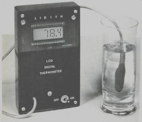
HERE IS AN easy-to-build battery-operated 3 1/2-digit thermometer, which we call "Lidith" for Liquid-crystal Digital Thermometer. It can accurately measure temperatures from -13° F to + 185° F. Basic accuracy is better than ±1° over this range and averages better than ±0.5° from 0° to 100° F. Each degree is divided into 10 equal parts, giving Lidith a 0.1° F resolution. Readout is on a 1/2" liquid-crystal display.
With some simple circuit modifications, Lidith can perform other functions, such as reading the temperature in °C and displaying both indoor and outdoor temperatures.
Circuit Operation. Shown in Fig. 1 is the schematic diagram of Lidith. (See Box for details on sensors.) Resistor R11 is the series voltage dropper for the 6.8-volt zener diode in the temperature transducer (IC2). The R12/C6 network provides additional stability if the transducer is used as a remote sensor. Resistors R9 and R10 form a precision voltage divider to insure that the proper proportion of the transducer's output voltage goes to the digital panel meter (DPM) circuitry.
Several points should be noted about the IC2 circuit. At room temperature (77° F), the transducer's output from pins 1 and 2 to pin 3 is nominally 2.98 volts and increases by 10 mV for every 1°C or 1.8° F increase in temperature.
This potential is measured with respect to +9 volts, not ground. This means that at 77° F, pins 1 and 2 are at-2.98 volts, with respect to +9 volts.
The heart of the DPM is the Intersil ICL7106 single-chip 31/2-digit MOS A/D (analog-to-digital) converter that drives the LCD. The 7106 uses dual-slope conversion, in which nonlinearities tend to cancel out. Therefore, the circuit does not require extremely accurate or stable (and expensive) components. Also, as long as it remains unchanged for a single conversion cycle, the clock frequency does not have to be precise or extremely stable. The only real requirement is a stable current reference.
==========
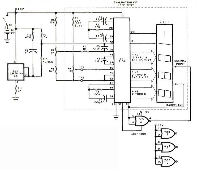
Fig. 1. Most of the components are supplied with the meter evaluation kit as shown within dashed lines. Temperature sensor and other components are connected to kit as shown here.
PARTS LIST
B1--9-volt battery
C1--0.1-µF capacitor*
C2-0.47-µF capacitor*
C3-0.22-µF capacitor*
C4-100-pF capacitor*
C5-0.01-µF capacitor*
C6-0.1-µF capacitor
DISP1--3 1/2-digit LCD display*
IC1--7106 3 1/2-digit A/D converter (Intersil)
IC2--LM3911 H-46 temperature sensor (National)
IC3--4001 quad 2-input NOR gate
The following are 5%,1/4-watt resistors unless otherwise specified:
R1-22,000 ohms
R2-47,000 ohms*
R3-100,000 ohms*
R4--1000-ohm trimmer potentiometer*
R5-1 megohm*
R6-12,000 ohms
R7--5000-ohm multi-turn trimmer potentiometer
R8-62,000 ohms R9-10,000 ohms, 1%
R10-40,560 ohms, 1%
R11-2000 ohms
R12-47 ohms, 10%
Misc.--Battery holder; IC socket; three-conductor flexible cable; 3/16" to 1/4" ID thin-wall brass or copper tubing; insulated tubing; E-PDX-E ribbon; acrylic spray; plastic case; 1/6"-thick clear plastic sheet; black spray paint; glue; machine hardware; etc.
*These items are supplied in the 7106EV Intersil Single Chip Panel Meter Evaluation Kit available for $34.95 plus 5% shipping & handling from Jameco, 1355 Shoreway Rd., Belmont, CA 94002.
Note: The following are available from Magicland, 4380 S. Gordon, Fremont, MI 49412: Kit containing one LM3911 H46, R9, and R10 for $9.95 postpaid (request #ST2RB for conventional kit, #CT2RB for Celsius version).
Also available separately: LM3911 H-46 temperature sensor (with data sheet) for $6.50; matched pair of LM3911H-46s (±1° C or better) for $20.00; R9 and R10 for $1.75 each.
==========
In addition to ease of use and relatively low cost, the 7106 has several other features that make it ideal for use in Lidith. Since the thermometer employs CMOS circuitry, it consumes little current (about 0.8 mA). It has true auto-zeroing, will directly drive LCD displays, and has a guaranteed ±1-count accuracy over its entire ±2000-count range.
The RC network for the 7106's internal oscillator is made up of R3 and C4.
With the values shown, oscillator frequency is about 48 kHz. Capacitor C3 and resistor R2 are the integrating components, while C1 is the reference capacitor and C2 is the auto-zero capacitor.
Low-pass RC filter R5/C5 is used for improved noise rejection.
A stable 2.8-volt reference potential between pin 1 (V+) and pin 32 (COMMON) is provided by the 7106. Resistors R1 and R4 form an adjustable voltage-divider network that applies a suitable proportion of this reference voltage to pin 36 (REF HI) and pin 35 (REF LO). Adjustment of R4 is made for a potential of 0.110 volt (110 mV) between REF HI and REF LO. In Lidith, R4 is basically a scale-adjust trimmer potentiometer.
Another adjustable voltage-divider that uses the 7106's 2.8-volt reference is made up of R6, R7, and R8. Notice that temperature-adjust trimmer R7s wiper is connected through filter resistor R5 to pin 31 (IN HI) of the 7106.
Once the thermometer is calibrated, with R7 at a fixed position, IN HI is at a fixed voltage. For the DPM to display 00.0, its IN LO (connected to the transducer's voltage-divider network) must be exactly equal to its IN HI point. Thus, after calibration, the voltage at R7s wiper must be identical to that coming from the transducer's R9/R10 divider net-work (and connected to IN LO) when the transducer's temperature is at 0°. We can conclude, then, that R7 can be viewed as a 0° trimmer pot. However, since 0° F is not easy to achieve, R7 will actually be set for a display of 32.1 when the transducer is immersed in ice water.
As the transducer's temperature rises, its output at pins 1 and 2 becomes more negative, with respect to +9 volts. This more-negative potential is felt at the 7106's IN LO input. When IN LO becomes more negative, with respect to IN HI (which is set at a constant voltage after calibration), the 7106 senses this as a positive voltage at its input, since IN HI is now more positive, or less negative, than IN LO. Therefore, the DPM displays a positive number.
When the transducer's temperature goes below 00, IN LO is less negative than IN HI and the DPM indicates a negative temperature.
The 7106 directly powers all segments of the LCD. Pin 21 goes to the display's backplane, while the front-plane segments connect to pins 2 through 25, excluding pin 21, which connects to the decimal point between the units and tenths decades in the display. Between the decimal point and pin 21 is a CMOS inverter that provides the proper ac voltage with an insignificant dc offset. It may seem wasteful to use an entire 4001 for this trivial task when a single MOS transistor would do the same job, but a 4001 is less expensive and more readily available.
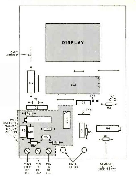
Fig. 2. The main outline here is that of the meter evaluation kit.. Thermometer
components can he added to the "open" area on the kit board created
by taking off the battery.
---------- TEMPERATURE SENSOR SUPPLIERS
There are a number of manufacturers who produce temperature sensors suitable for use with Lidith. The following is a list of a few such manufacturers, followed by brief descriptions of the suitable sensors.
Precision Monolithics Inc. ( 1500 Space Park Dr., Santa Clara, CA 95050) produces Ultra-Matched Monolithic Dual Transistors, Series MAT-01, which, with suitable amplification, can be used in an electronic thermometer. For details, consult the company's application note No.
AN-12 titled "Temperature Measurement Method Based on Matched Transistor Pair Requires No Reference." Analog Devices (Rte. 1, Industrial Park, P.O. Box 280, Norwood, MA 02062) has recently released the AD590 Two-Terminal Temperature Transducer. It produces an output current proportional to the absolute temperature. At room temperature (77 F or 25° C), a 298.2-µA output is available. For every 1' C rise or fall, current increases or decreases by 1 µA. Premium model AD590M has a guaranteed maximum calibration error of ±0.5° C at 25° C. If you prefer to deal with voltages instead of currents, simply add a precision resistor in series with the transducer.
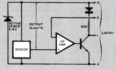
National Semiconductor Corp. ( 2900 Semiconductor Dr., Santa Clara, CA 95051) produces the LM3911 IC tempera-ture transducer specified in Lidith's Parts List. As shown in the diagram in this box, the transducer includes a built-in operational amplifier, internal zener diode to provide voltage regulation, and output transistor whose collector can be returned to a potential as great as 36 volts.
turned to a potential as high as 36 volts.
There are undoubtedly other semiconductor manufacturers who make sensors and transducers similar to those mentioned above, and this is not intended to be a complete list.
---------------
Construction. Unless you can obtain a suitable 3 1/2-digit LCD at reasonable cost, we strongly recommend Intersil's ICL7106EV/KIT Single Chip Panel Meter Evaluation Kit. It is available from Jameco (see Parts List) and other Intersil distributors. If you are set on building your thermometer from scratch instead, follow Fig. 1 and the pin configuration guide for the LCD you buy.
Except for the remote sensing transducer, all thermometer components mount on the Evaluation Kit's circuit board. Build the Kit following the instructions supplied with it. Then, referring to Fig. 2, replace R1 supplied with the Kit with a 22,000-ohm 5% (or better) tolerance carbon or metal-film resistor. (If you can adjust R4 for 0.115 volt or more between TP2 and TP3, R1 need not be changed.) Eliminate the battery holder, specified jumper, and banana jacks. Drill holes for and mount the extra circuitry as shown. Refer back to Fig. 1 and interconnect all on-board components.
A 1" to 2" (25.4to 50.8-mm) length of 3/16" to 1/4" (4.8to 6.4-mm) inner-diameter thin-walled brass or copper tubing should be used as a heat sink for the transducer if you plan to measure air temperatures. If you plan to use Lidith primarily for taking body and liquid temperatures, you can omit the tubing. Use a length of flexible three-conductor cable to interconnect transducer and circuit assembly. The cable can be up to 50' (15.2 m) long with no problems.
Referring to Fig. 3, slip the metal tubing onto the cable as shown. Then remove about 1" of the cable's outer jacket and prepare the ends of the conductors.
Slip a length of plastic tubing over each conductor. Using a heat sink between transducer and tie points, solder the conductors of the cable to the leads on the transducer. Then spray several coats of plastic insulation (such as GC's Koloid K-29 or Clear Acrylic Plastic) over the connections and exposed wires. Alternatively, dip the entire transducer assembly in GC Liquid Tape. When the coating dries, push the plastic tubing down until it contacts the transducer's body and covers all bare wires.
Clean the transducer and metal tubing with fine steel wool or sandpaper. Referring to Fig. 4, solder the transducer to the tube, taking care to be sparing with the heat.
Finally, use epoxy putty to make a waterproof probe out of the transducer assembly. Prepare the putty according to directions and then wet your hands and form a rough cylinder around the transducer assembly. Do not be concerned if your work appears messy. Just make sure the transducer and connections are completely sealed. With damp hands, roll the rough cylinder between your hands until it is smooth and nearly perfectly cylindrical and has a blunt cone-shaped tip.
Mount the thermometer circuit inside a housing large enough to accommodate it and its battery.
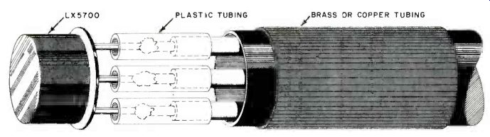
Fig. 3. Temperature probe construction. Make sure all soldered connections
are well insulated. Thin metal tubing is optional.
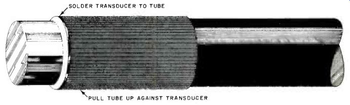
Fig. 4. Solder the optional heat sink to the heat sensor. Then, use epoxy
putty to form a waterproof probe out of the transducer assembly.
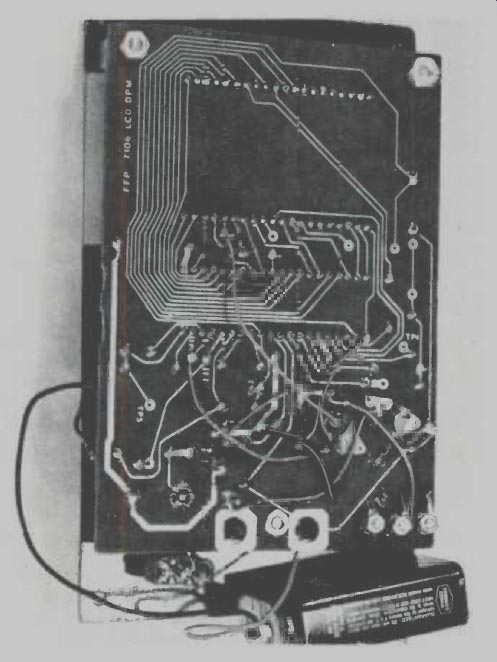
------------ Photo showing back of meter evaluation kit hoard after
extra holes have been drilled and components for temperature sensor have
been added.
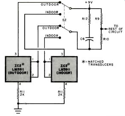
Fig. 5. Diagram shows how to connect two temperature sensors to the basic
thermometer. For best results, sensors used should be matched.
Calibration. If possible, the following reference-voltage adjustment should be performed with the aid of a digital multimeter. However, a good-quality analog voltmeter can be used if its input impedance is 1 megohm or greater. If you have a laboratory thermometer, you can do away with the need for a meter altogether, but calibration will take considerably more time. (More about this later.) Turn on the power and let the thermometer warm up for at least 2 minutes.
Then, with the meter set to its lowest range, connect the negative prod to TP3 (actually a jumper) and positive prod to TP2. Referring to Fig. 2, carefully adjust R4 for a reading of 0.110 volt.
To calibrate the thermometer, you will need a plastic bucket filled about three quarters full with compact clean snow, ice chips, or ice cubes. Pour in enough cold water to nearly fill the bucket. Place the transducer probe in the center of the ice/water mixture and wait a few minutes until the LCD stabilizes at some number.
Vigorously stir the ice mixture and adjust R7 for a display of 32.1. This display figure is more desirable than the usual 32.0 because you will most likely be performing calibration in a warm room where ice in water will be melting.
In any event, what you are really measuring is the temperature of the water, which will not be exactly 32° F. If Lidith is calibrated exactly as described above, there are only two possible sources of error left-the transducer's slope and linearity errors. Fortunately, the transducer specified is almost perfectly linear. According to the conversion specifications, the linearity of the LM3911 is typically less than ±0.05%. The only possible significant error left, then. is a slight slope error. With a laboratory thermometer and some patience, even this error can be removed.
To remove the slope error, adjust R4 and R7 exactly as described above. (If a DMM is not available, initially set R4 to its midpoint.) Place the probe and lab thermometer in warm (about 120° F) water and, while stirring the water, adjust R4 until Lidith's display indicates exactly the same temperature as the lab thermometer. Then place the probe in a bucket of ice/water and adjust R7, if necessary, for a reading of 32.1. Return the probe to the warm water and, if necessary, readjust R4. Repeat the immersion-and-adjustment procedure until it is no longer necessary to trim the settings of the potentiometers.
Using the Thermometer. In addition to the obvious use of measuring room and ambient temperature, Lidith is ideal for measuring temperatures in pools, for isolating excessively warm electronic components in an operating circuit, as a remote-indicating freezer or refrigerator thermometer, and as a medical thermometer. (If you calibrate accurately for 98.6° F against a good-quality oral mercury thermometer, the accuracy of Lidith can approach-±0.1° F over a 92° to 110° F range.) The Celsius version can also be used by auto hobbyists as a water-temperature monitor.
To accurately measure outside-air temperatures, you need both an accurate thermometer like Lidith and a suitable thermometer shelter. (For details on measuring outside-air temperature, see pages 23 and 25 of Unique Electronic Weather Projects published by Howard W. Sams & Co., or refer to some other suitable book on weather instruments.) If you turn on Lidith only when you wish to know the temperature and leave the power off at all other times, a standard 9-volt battery should last more than a year. For a continuous display, omit S1 and use six alkaline D cells in series instead of the 9-volt battery. In continuous use, the D cells should last about a year or more.
The thermometer can be used to measure temperatures in two different locations, such as indoors and outdoors, using the circuit shown in Fig. 5.
Bear in mind, however, that if you select two LM3911H-46 transducers at random, one of the temperatures measured will typically be off by 5° to 10° due to the offset error of the devices. However, if you use a pair of custom-matched transducers (see Parts List), your maximum error will be ±2° F. With a few changes in component values, you can make Lidith measure temperatures in Celsius over a range of from-25° to +85°C. The following changes are required for the Celsius version. First, change C2 to a 1-µF Mylar capacitor, R2 to a 220,000-ohm, 5%-tolerance carbon-film resistor, and R4 and R7 to 10,000-ohm, 15-turn trimmer potentiometers.
Then adjust R4 so that the potential between TP2 and TP3 is 0.500 volt. Also, change R6 to 20,000 ohms, R8 to 22,000 ohms, and R10 to a 10,000-ohm, 1 %-tolerance precision resistor.
Calibrate by adjusting R7 for a reading of 00.1 on the LCD when the probe is immersed in an ice/water mixture, as before.
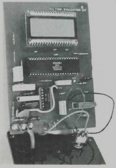
---------- Front view of meter evaluation kit showing components for
temperature sensor added in area where battery holder was.
Summing Up. Lidith is a truly state-of-the-art precision digital thermometer. With a few minor changes, it can be "tailored" to your needs. And, in ordinary use, it is highly energy-efficient, thanks to the use of low-power MOS circuitry and liquid-crystal display.
Source: Computers and Electronics--Experimenter's Handbook (1984)
Also see: Build a Diode Temperature Probe