Eliminate risk of damage to electronic ignition systems.
BY JOHN E. DAVIS
PERFORMING your own automobile tune-ups can be a source of personal satisfaction as well as a way to save money, but if you own a late-model car with electronic ignition, you'll find that the process is not what it used to be. Many modern ignition systems are magnetically triggered and have no points to adjust, thus relegating dwell meters to museums. However, the anti-pollution devices on modern engines have made idle speed considerably more critical than it once was, so an idle tachometer is still required. Since some of these systems can be severely damaged by momentarily grounding the tachometer tie-in point, the problem is where and how to connect the tach without damaging the ignition module.
The best way would be to avoid electrical interconnection with the ignition system entirely, and you can achieve this by building the Wireless Idle Tachometer described here. The tachometer is designed to operate with any four-, six- or eight-cylinder, four-cycle engine having spark ignition. It can be used with two-cycle engines, but the meter indications will be twice the actual engine speed.
Idle tachometers generally indicate from 0 to 1000 rpm. However, partly for ease of calibration it was decided to extend the range of the tachometer described here to 2000 rpm.
Circuit Operation. The tachometer circuit (Fig. 1) uses a two-transistor monostable as a frequency-to-current converter. The input signal is radiated from the ignition system and picked up on a small telescoping (portable radio-type) antenna nearby; the output is displayed on a meter.
Under quiescent conditions, Q1 is off and Q2 is on. Since the collector of Q2 is low, there is not enough voltage to forward-bias series-connected diodes D3 and D4 and produce a current flow through R10, R11, and M1.
---------------
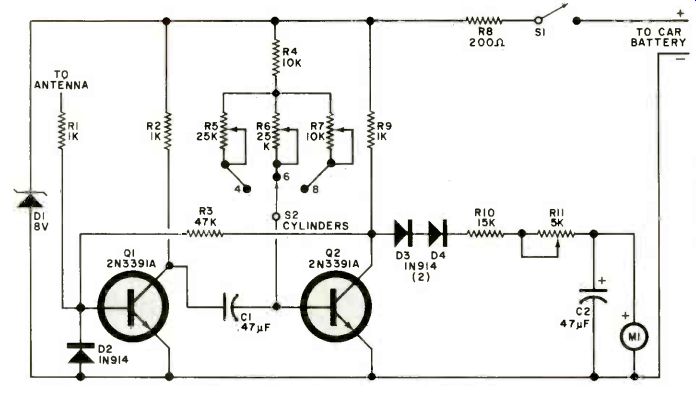
Fig. 1. The tachometer uses a two-transistor monostable circuit as a
frequency-to-current converter.
PARTS LIST
C1--0.47-µF capacitor
C2--47-µF electrolytic
D1--8-V, 1-W zener diode
D2,D3,D4--Silicon diode (1N914 or similar)
M1--200-µA meter
Q1, Q2--2N3391A transistor
R1, R2,R9--1-kO, 1/2-W resistor
R3--47-kO, 1/2-W resistor
R4-10-kO, 1/2-W resistor
R5,R6--25-kO, mini-pc potentiometer (Radio Shack #271-336 or similar)
R7--10-kO mini-pc potentiometer (Radio Shack #271-335 or similar)
R8--200-Ohm, 2-W resistor
R10-15-kO, 1/2-W resistor
R11--5-kO linear-taper potentiometer
S1--Spst toggle switch
S2-Three-position rotary switch
Misc.--Telescoping portable radio antenna, suitable plastic enclosure, two-conductor power cable, battery connector, etc.
-------------------
When the antenna picks up a positive-going ignition signal, Q1 turns on and forces Q2 to turn off for an interval determined by the time-constant of C1 and the resistance selected by switch S2. The choice of time constant sets the tach for 4-, 6-, or 8-cylinder engines.
When turned off, the collector of Q2 rises to deliver a constant-voltage, constant-duration pulse to the meter network. Meter M1 will indicate the current flow. When each positive-going ignition pulse finishes, Q1 returns to its cutoff state, and Q2 reverts to its conducting state. This stops generation of the meter pulses.
As the ignition system rapidly cycles on and off, the two-transistor circuit will follow, and the meter needle will flutter. This is prevented by C2 which smooths the current pulses.
Potentiometer R11 provides means to compensate for errors due to ambient temperature variations. For example, if the ambient temperature is 20" F different from the temperature at which the tachometer was calibrated, an error of about 25 rpm will be found. If you are not overly concerned about temperature variations, use a fixed 2,200 ohms for R11. Resistor R8, in conjunction with zener diode D1, maintains a constant 8 volts for the circuit. Switch SI is the on/off switch. Diode D1 protects Q1 from negative spikes, while R3 provides the necessary feedback.
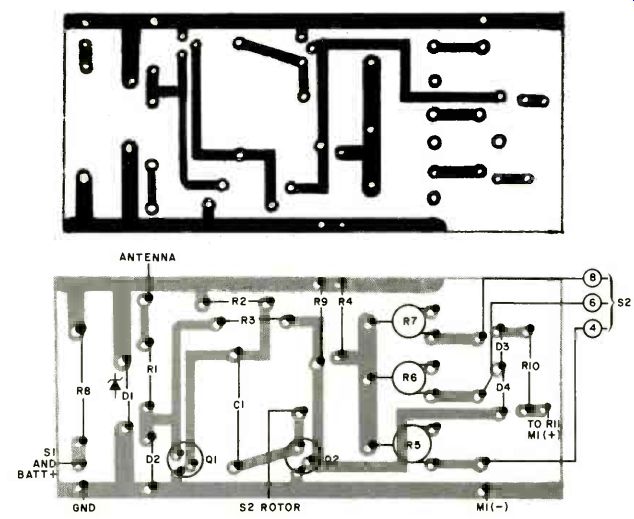
Fig. 2. Etching and drilling guide (top) and component layout diagram
for a printed-circuit board for the tachometer.
Construction and Calibration. Circuit layout is not critical and the builder may use point-to-point wiring on perf board or the printed circuit board shown in Fig. 2.
Meter M1, switches S1 and S2, and control R1 are mounted on the top panel of the case. Capacitor C2 is mounted directly on the meter terminals. The two-conductor power cable exits the case where convenient.
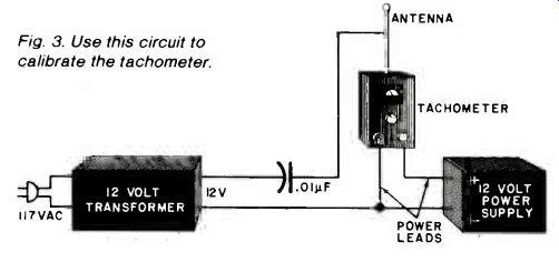
Fig. 3. Use this circuit to calibrate the tachometer.
The antenna can be mounted in any part of the case where space allows, with a hole drilled so that the antenna can be extended. If you use a plastic case, it isn't necessary to insulate the antenna. If a metal case is used, insulation will be required whenever the antenna connects to, or passes through, the cabinet.
Calibration requires a 12-volt dc power supply (or a car battery), a 12-volt transformer, and a capacitor (approximately 0.01 µF). These components are arranged as illustrated in Fig. 3.
Turn the tachometer on and allow a few minutes for temperature stabilization. Position R11 to the center of its rotation. This point should be marked on the case for future reference. Set cylinder-select switch S2 to "4" and adjust R5 for a meter indication of 180 (1800 rpm). Place the switch to "6" and adjust R6 for an M1 indication of 120 (1200 rpm), then set the switch to "8" and adjust R7 for 90 (900 rpm). If R1 is left in the circuit and the user wishes to recalibrate the unit for accurate readings at an elevated or reduced ambient temperature, the procedure is as follows. At that ambient temperature chosen, hook up the circuit shown in Fig. 3, and adjust R11 for the correct reading on any of the three settings of S2. The other two scales will also be correct, since R11 adjusts all three scales simultaneously. Potentiometers R5, R6, and R7 should not be readjusted for temperature compensation.
Use. With the vehicle engine running, hook the tachometer power leads to the car battery, turn it on, wait approximately one minute, then extend the telescoping antenna. Set cylinder-selector switch S2 to the proper setting and hold the antenna about one or two feet over the engine.
You should get a stable indication of engine rpm. If the display is erratic and the needle jumps around, there is insufficient coupling between the ignition system and the antenna. This is most likely to occur when the car's ignition wires are concealed by the air cleaner or some other metallic element. If this is the case, move the antenna closer to the ignition coil or distributor. If you get no meter display, the power leads of the tachometer may be reversed. This will keep the unit from operating, but won't damage it. Once you get stable readings, you can tune your car accurately and be confident that you won't "blow" costly ignition parts.
Source: Computers and Electronics--Experimenter's Handbook (1984)
Also see: Using the 4060 as a Timer
Curb "Fuelishness" with the Automotive Econometer