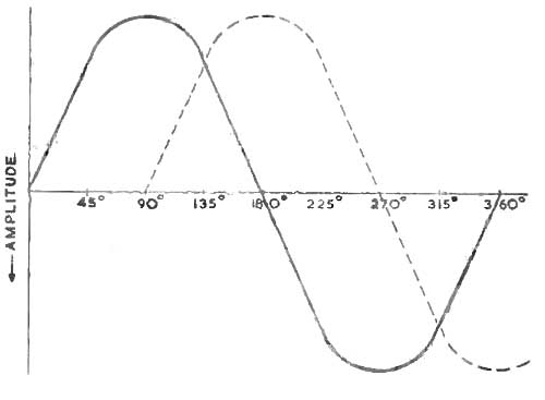
Fig. 1. Illustrating Phase Shift.
Whatever the final function of the apparatus there is no radio and almost no electronic device which does not rely to a great extent on coils. In broadcast receiver design the radio frequency coil with its associated condenser forms the heart of the circuit and the whole excellence of the final output depends upon its working whilst such gear as audio amplifiers, cathode ray oscillographs, relay operators, sound heads and photoelectric devices all depend on coils in the shape of transformers for power supply and coupling, smoothing chokes and audio or radio resonant circuits.
Whether the coil is designed for high frequency working and is a simple helix supported in air or whether it is for power transformation at a low audio frequency, consisting of thousands of tutus of wire on an iron core, its basic operation is the same.
All coils exhibit the same qualities, the most important being:
(1) Inductance
The inductance of a coil (coils are often known as inductors) is the measure of its electrical inertia. To generate a current in a wire and thus develop a voltage across the wire's ends it is merely necessary to move the wire through a magnetic field so that it cuts the lines of force, when the current will depend on the rate of cutting and the number of lines cut, this being the well-known principle of the generator. Moreover, moving the wire one way through the field and then reversing its direction of travel will cause the current to reverse its 'direction of flow-it will commence at zero and grow to a maximum, fall back to zero as the movement slows and stops and on the return of the wire through the field will grow to a maximum again but in the opposite direction of flow.
This current, of course, is A.C. or Alternating Current, whilst current which always maintains one direction of flow is D.C. or Direct Current.
Current may also be generated in the wire, however, by arranging it in a fixed position and allowing the magnetic field to vary around it, the lines of force growing and collapsing and so cutting the wire as before. Obviously any current so obtained must be A.C. and the frequency will depend on the rate at which the magnetic field grows and collapses, or in the came way, on the rate at which the wire in the earlier examples reverses its direction of travel. One complete alternation from zero to maximum in one direction, back to zero and on to maximum in the other direction and finally back to zero is known as one "CYCLE" (the number of Hz being known as the frequency) and corresponds with one complete revolution of the rotor of a simple alternating generator. Thus we can say that such a cycle takes place over 360 degrees, and if it is desired to inspect only a part of a cycle we can measure any part of a whole cycle along the zero line and give it an angular measurement of, say, 90 degrees or one quarter of the cycle, whilst if we desired to compare two alternative voltages of the same frequency where one grew to its maximum one quartet of a cycle after the other we would say that there was a "PHASE DIFFERENCE" of 90 degrees between hem or that they were "90 degrees out of phase." In Fig. 1 the continuous line shows one cycle of voltage, the time of the cycle being measured along the zero line in degrees while the broken line shows a similar cycle of the same frequency 90 degrees out of phase. Moreover the crest or maximum point of the broken line is after that of the continuous line cycle, so that 0 "I LAGS" behind the continuous line by 90 degrees or the continuous line cycle is "LEADING" by 90 degrees.
It may be said here that usual frequency of the A.C. mains in this country is 50 Hz ( Hz) while audio waves extend from roughly 20 to 20,000 Hz and radio waves are arbitrarily divided into bands between roughly 100,000 to 300,000,000 Hz
1,000 cycles are known as a KILOCYCLE (kc.) or kilohertz (khz) and 1,000,000 are a MEGACYCLE (Mc.) or megahertz (mhz).
A coil or inductance, then, may be fed with any of these frequencies depending on the task it is to perform, but to understand what happens suppose a simple coil, a solenoid of a few turns of wire on a simple former, is connected to a battery through a switch.
When current flows through a coil it causes a magnetic field to form, the axis of the field being down the center of the coil, so that if the switch of the above circuit is closed current will flow through the coil and the magnetic field will suddenly grow. As it grows, however, the lines of force, extending outwards, cut the wires of the coil which is the necessary condition for generating a current in those wires The growing field of a coil always generates this current in opposition to the current from the supply and so it is plain that the full battery voltage will not at first appear across the coil for it will be reduced by the voltage due to the current generated in the coil itself.
Obviously this will affect the battery current, making it a smaller flow than it would otherwise be, and not till the whole system is in equilibrium will the current rise to its maximum value. When the circuit is broken the magnetic field collapses and once more the lines of force cut the wires inducing a voltage which this time endeavors to assist the falling voltage and thus endeavors also to bolster up the falling current, these effects, of course, occurring in the fraction of a second. These voltages, generated to oppose any change of condition of the coil, are sometimes known as "BACK E.M.F.s" and may be quite high, depending on the inductance of the coil. In an electric hell, for instance, it is the self-induced voltage which gives the spark at the contacts and experiment will show that the Back E.M.F. is sufficient to give a smart shock.
This, then, is the effect of the coil's inductance, and obviously it will be of great importance when the coil is fed with A.C. The current is always rising and falling in value so that there will always be a voltage induced by the coil's own field and affecting the current flow in the coil. In a pure inductance the current would lag behind the voltage by 90 degrees, thus in Fig. 1 the continuous line curve could now represent the A.C. voltage across a coil with the broken curve representing the lagging current, so that at full voltage the current is only just beginning to flow.
The unit of inertia, or inductance, is the HENRY and as it is proportional to the rate of change of the current a coil is said to have an inductance of 1 henry when the current, changing at the rate of i ampere per second, causes a pressure of 1 volt to be induced across the coil.
The henry is too large a unit for use with radio frequency coils and they are measured in millihenrys (mh.) or in microhenrys (uh.). The symbol for inductance is L.
(2) Reactance
A coil has its own ordinary resistance to a steady current, measured as usual in ohms, but as it opposes the sudden changing of currents and voltages it obviously has a secondary effect on A.C.
Alternating currents will have to overcome not only the ordinary resistance but also this "Reactance" and the opposition to A.C. of the coil is given by the formula: XL = 2 π fL where X_L is the reactance of the coil in ohms. f is the frequency of the A.C. applied. L is the inductance of the coil in henrys and pi equals 3.14.
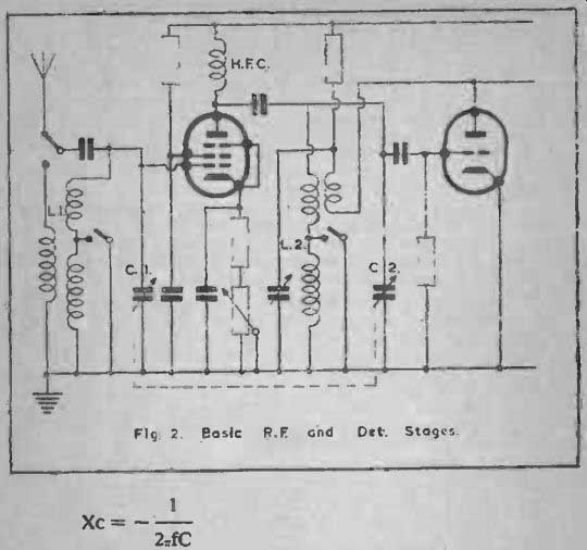
Fig 2 Basic R.F. and Det. Stages.
R.F. coils are usually coupled with condensers, and the capacity has an effect on A.C. exactly opposite to that of the inductance.
It causes the current to lead the voltage, and so the effect of placing inductance and condenser together in a circuit is largely to cancel out their reactances. For a condenser: -
Xc = - ½ pi fC
where Xc is the reactance in ohms and C is the capacity in farads.
It must be noted that the result is expressed as a negative quantity.
Reactances may be added together.
(3) Impedance
Impedance is denoted by the term Z and when Ohm's Law is applied to A.C. Z takes the place of R, the term for D.C. resistance.
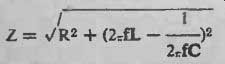
When a circuit contains resistance and reactance although both terms are in ohms they cannot simply be added. The formula:
Z = __/ [R2 + X2] ohms must be applied, and where a circuit contains a resistance R ohms, an inductance L henrys and a capacity of C farads in series, the impedance will be:
-------
An inductance and capacity together have:
(4) Resonance that is they respond to a resonant frequency with their lowest impedance if they are in the series or with their highest impedance if the inductance and capacity are in parallel. Thus inductance and capacity in parallel and tuned to their resonant frequency develop their highest voltages in phase opposition at that frequency and are the most usual form of tuning circuit as shown in Fig. 2.
The formula for the resonant frequency for either series or parallel circuits is:
… and it must be noted that here the values have been reduced to working practical values; f is in kilocycles, L is in microhenrys, and C is in picofarads or micro-microfarads.
(500 picofarads = .0005 microfarads, a common size for tuning capacitors).
(5) Dynamic Resistance. RD.
As a coil and capacitor in parallel present a high impedance to their resonant frequency. as is generally desirable so that they may develop a good voltage, the ratio L/C is important and the impedance of such a circuit at resonance may be given as L/CR, this often being known as the Dynamic Resistance. It is plain, therefore, that R.. the coil's H.F. resistance, has a large hearing on the dynamic resistance RD and affects the efficiency of the whole circuit. This efficiency is known as the (6) "Q" of the circuit and may be shown as:
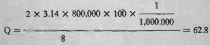
Q= 2 pi fL/R
R where f is in Hz, L is in henrys and R is in ohms. For example, a coil of 100 microhenrys inductance with a resistance at 800 kilocycles of 8 ohms would have a "Q" of
It must be realised that the coil resistance R grows higher with a rise in frequency due to losses and the skin effects of the wire, and cannot be taken as the resistance to D.C. Also a coil can never displace current and voltage by the full phase shift of 90 degrees because a pure inductance is impossible-the turns of wire have resistance and a sell -capacity one to the other, while a condenser, on the other hand, sometimes displays quite a large inductive effect.
As "Q" is a measure of efficiency it is also known as the magnification factor of the coil. Clearly if the coil and condenser system has a resonant frequency a charge induced in such a system will not die away rapidly. The condenser will become charged, will discharge through the coil and so reverse its charge, the coiling to maintain the current flow, will discharge again and so produce a train of waves each of slightly less amplitude until they finally disappear. The circuit is heavily damped and has a low "Q" if these oscillations die away rapidly and vice versa.
The desirable features of a coil may now be summed up.
It should be as "pure" an inductance as possible-that is, its self -capacity due to humped turns of wire, heavy former and the design generally must be small, the resistance to high frequencies must be kept low, it must be rigid and of strong construction, frit obviously any misplaced or disturbed turns of wire will change the inductance, it must not be susceptible to humidity changes in the atmosphere-dampness might cause leakages from turn to turn and as the coil has a varying magnetic field it must not be brought too close to any mass of metal for eddy currents would he induced by the field and the efficiency of the coil reduced. For that reason screening cans must be of a correct size which, as shown later, ma) be calculated.
(7) Mutual Inductance
The coil has a varying magnetic field in and around it and this will induce a voltage across any other coil in the vicinity if the lines of force are able to cut the wires of the second coil, the wave -form of the induced voltage being a pattern of that on the original coil This linking of two coils by the magnetic fields around them is known as mutual inductance, and its symbol is M.
Mutual inductance may be either desirable or not, depending on the circuit. For example, in Fig. 2 the second valve (tube), a detector triode, has a reaction coil connected to its anode whose function is to Feed back energy into the grid coil. Here mutual inductance is very necessary, but the whole coil set of the detector valve (tube) must be screened completely from the coils of the first valve (tube) or energy will be fed back into the first stage with consequent uncontrollable instability.
Again, in Fig. 3. the I.F. Transformers have their windings coupled by mutual inductance, but each transformer is carefull3 screened from all other coils.
The types of R.F. coils used in receivers vary according to the circuits, but Figs. 2 and 3 give some idea of what is needed. Fig. 2 is of a basic circuit for a "straight" receiver, the first being a high frequency amplifier followed by the second stage, a triode detector Obviously it will be very desirable to make C, and C, a ganged two-section condenser but before this can be done the two sets of coils must be similar in all respects so far as the actual tuning windings are concerned. The other windings will put varying loads on these tuning coils in each case, causing damping to some degree but these effects can be balanced in practice. In the first stage the aerial will impose its load on the grid coil via the aerial coil, and in the detector stage the anode coil will be coupled to the grid coil as well as the interstage coupling, but if the two grid coils are made identically similar these loads will be balanced by keeping couplings low and. finally, by trimming out stray capacities with the trimming sections of the ganged condenser.
It will be seen that the grid coil is in two parts in each coil set, one winding being short-circuited by a switch. This winding is the long-wave coil. the unswitched coil in both races being the medium-wave coil. and these switches must also be ganged. If further wave bands are required their coils may be wound on the same former with extra switching, but for good results on short waves it is advisable to isolate each winding and make it a separate coil with grid and aerial and grid and anode windings as desired. These coils are then mounted round a rotary wafer switch so designed (with an earthing ring) that all coils not in use are short-circuited and earthed to prevent pick-up and other losses, and each set of coils is screened in its own box built round the switch.
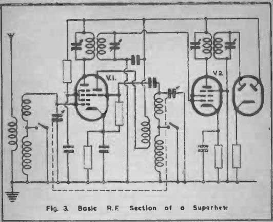
Fig. 3. Basic R.F. Section of a Superhet.
For a superhet (Fig. 3) the coil systems are rather more complex.
The first stage is a mixing circuit where incoming signals are tuned by L1 and C1 and fed to a triode-hexode. The triode portion of the valve (tube) is an oscillator with its own set of coils arranged to tune to a frequency which, no matter what the position of the ganged condenser, is always a constant number of kilocycles different from the incoming signal. This difference is known as the Intermediate Frequency and the oscillator is usually tuned above, rather than below, the frequency being received. These two frequencies are mixed in the valve (tube) and the result is a modulated signal composed of the Intermediate Frequency and the sound signals from the trans miner.
The primary winding in the anode circuit of V1 is tuned by a small condenser to this frequency so that a modulated high frequency voltage is set up across this coil and a similar voltage is induced into the secondary winding also tuned, the two coils together forming an Intermediate Frequency Transformer. The induced voltage is fed to the grid of V2 and again passes through an I.F. Transformer before reaching the detector, V3.
The aerial and oscillator coils are similar to those as used in a straight receiver, but the I.F. Transformers tune to a lower frequency (about 465 kHz) and thus need more turns of wire and a greater inductance. An I.F. Transformer is. in effect, a Band Pass Filter and as explained in SECTION 2 this greatly assists selectivity in tuning.
There are several methods of improving the selectivity of a receiver. In the straight set reaction can be used in the detector stage to give greater selectivity and volume with a slight drop in tonal quality or several tuned stages may be employed, each consisting of a grid coil and tuning condenser coupled through an H.F. amplifying valve (tube) to the next stage. It is plain, however, that instability would soon be caused by the multiplication of valve (tube)s, and generally it is better to reduce the number of stages by using Band Pass Filters instead of single coils. Each Filter requires two tuning condensers instead of one so that a ganged condenser for more than one stage becomes an unwieldy affair, but with a straight receiver good results are obtained by using a Band Pass Filter with the H.F. stage coupled to a single coil grid circuit.
Band Pass Filters of different types are shown in Fig. 4 and their action may briefly be explained as follows. Where two coils have identical resonant frequencies these frequencies are slightly changed by coupling the coils, one moving higher and one lower.
Thus two coils coupled to the correct degree spread a single turning point over a hand although the limits of this band arc far more sharply defined than the limits of a tuning point on a single coil Not only is the selectivity increased, but a station on the band of frequencies has a more even response accorded to its sidebands with a consequent improvement in quality.