For home construction, only R.F. coils on open air -cored formers will be considered as apart from S.W. and Television coils, for there is no really satisfactory method for the construction of coils using powdered iron cores.
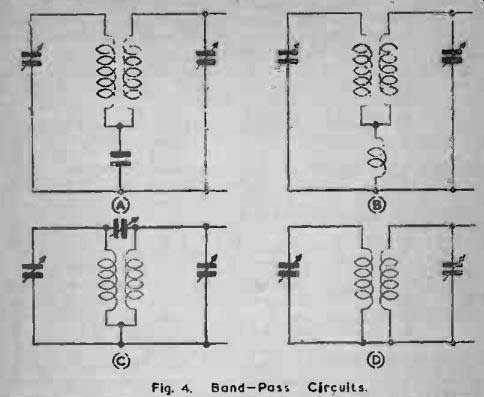
Fig. 4
The steps to be described are:
1. Design of the coil and determination of inductance.
2. Choice of former and type of wire.
3. Construction.
4. Testing.
1) Design
Obviously the whole design of the coil will depend upon the work it is expected, to perform. A medium wave tuning coil will consist of a single layer solenoid with or without reaction and aerial coupling coils. multi-range coils will contain both single layer solenoids and bank wound coils for the higher inductances, I.F.T.'s will, generally speaking, be bank wound coils made to fit on a dowel former and so on.
For tuning coils it is first necessary to consider the wave range the coil is to cover with due regard to the variable condenser to be used. and here it is advisable to use the formula A = 1885 4/LC where A is the wavelength. L is the inductance in microhenrys and C is the capacity in microfarads. Wavelength has a fixed relationship to frequency, the product of the two being 300,000.000
i.e., Axf= 3 X 10^8
E. H. Chapman has described one method for evaluating. We required inductance from the above formula. Variable condensers have a minimum and a maximum capacity, the stated value being the maximum. The minimum depends on good design and the amount of insulating material used in the construction, and there is a further stray capacity in a tuning circuit due to the wiring of the coil, shields, etc. If, however, the minimum capacity of the condenser is assumed to be zero then the stray capacities of the tuning circuit can be called S. and the formula written:
Lambda=1885 __/L(C + S)
This is the value for maximum capacity; obviously the wave length for minimum capacity is:
= 1885 LS
Square both equations: t A2 = 18852 L(C + S) = 18852 LC + 18852 LS.
Lambda_1 = 1885 _/ LS.
and by subtracting from t A2 - Al2 = 18852 LC.
In this form the formula is very useful for it enables any maximum and minimum wavelength to be referred to the coil and capacitor and by transposition L is easily found.
Example 1.
It is required to tune from 200 to 500 meters using a .0003 variable capacitor. Then:
5002- 2002 = 18852 x .0003 x L.
and 210,000 = 1,066L.
210,000 1,066
= 197 microhenrys.
It should be borne in mind that a tuning system is more efficient so far as range average is concerned the higher the LIC ratio can be made. that is by using a low capacity condenser with a high inductance, but clearly this is limited in the higher wave -ranges. At low wavelengths the band covered reduces, and adequate coverage is obtained by using several coils with the condenser to cover the bands. As the wavelength falls so will the capacity of the condenser as may be seen by considering a high frequency tuning system with a range of 5 to 8 meters.
Example 2.
A suitable condenser would be of .00005 mfd. capacity (generally styled 50 picofarad (pF)).
Then 82 - 52 = 18852 x .00005 x L.
or 39 = 177.7L.
L = .22 microhenrys.
The stray capacities in such a circuit would obviously have to be reduced to the smallest degree and the coil would be self-supporting, no former would be used. As the inductance is so low the connecting wires to the condenser must be as short as possible--usually the coil is mounted directly on the condenser terminals-for any loops of wire would add seriously to the inductance, perhaps even doubling its value.
This, then, demonstrates the differences between various types of coils, so far as structural methods are concerned, and a series of general suggestions may be given here.
Television Coils
Coils for television receivers differ considerably from other types since the requirements are different. High "Q" is not required, in fact it is a serious disadvantage and to avoid it the wire used in their construction is much finer than would be found in an ordinary receiver covering the same band of frequencies. It is virtually impossible for the amateur constructor to work out from a given formula the precise number of turns required to cover a given channel since so much depends on the nature of the core material, and the stray capacities in the chosen circuit. For intending television constructors full winding data will be found in Appendix II, page 83.
The information given covers all the existing B.B.C. channels and gives details of R.F. coils, R.F. transformers and chokes. With the exception of the chokes, calculations arc based on the Aladdin former and dust coil type F804.
Ultra Short Wave Coils. 4 to 10 meters
These may be wound on formers or he self-supporting. If the main desired waveband is about 5 meters self-supporting coils are advisable although if the coil is one of several, as in a superhet, where ganging is necessary a former must be used for the sake of rigidity.
Formers may be of ceramic materials such as are advertised, these formers often being chased with a very shallow spiral so that the wire is more firmly held. It is sometimes stated that copper or silvered copper tubing should be used for Ultra Short Wave work, but this is unnecessary even in small transmitters, let alone receivers.
No. 16 or 18 S.W.G. copper wire is perfectly suitable and this may or may not be silvered. The spacing between turns need not be greater than the diameter of the wire used: some spacing is desirable to cut down the self capacity of the coil but greater spacing than one diameter merely has the effect of reducing the inductance disproportionately.
Spaced coils, therefore, are best wound by taking two lengths of the wire to be used and winding them side by side on the former, the spacing wire being stripped away after varnishing (if done) to leave the actual winding spaced out by the wire's diameter. Spacings of smaller size may be made in the same way using various sizes of wire alongside the turns of the coil.
The leads of Ultra Short Wave coils should be made by merely leaving sufficient of the winding wire for connecting up at each end, this being cut down to the smallest length possible when the coil can be tried out in position.
Short Wave Coils. 10 to 180 meters
These coils may be made on the formers already suggested, on paxolin formers or on ribbed ebonite tubes, the wire sizes being graded down in diameter as the wavelength rises. Above 100 meters spacing will probably be dispensed with, the turns being wound to touch and here insulated wire will be needed. For all general purposes enameled wire is suitable, the insulation being thin yet strong: the wire must be handled with care, however, for the enamel can be cracked or scratched especially if the wire be allowed to kink.
Keep coils of wire wrapped and boxed so that sharp edges cannot rub the insulation.
Once again connections should be made by leaving sufficient of the winding wire at each end of the coil for that purpose.
Medium Wave Coils. 200 to 600 meters
These coils arc usually single layer solenoids wound with the turns side by side and touching. They are made on paxolin formers using enamel, cotton or silk insulated wire, and the ends of the windings should terminate in soldering tags so that connections may easily be made with no risk of poor joints.
Long Wave Coils. 900 to 2,000 meters (And I.F.T.'s)
These coils are most often bank wound, that is they are made of several layers of wire one layer on top of the other. Small paxolin bobbins may be made for the purpose or paxolin cheeks fitted over a cylindrical former, particularly where both Medium and Long wave coils are being wound together. Cardboard or paxolin cheeks might be fitted over i" dowel rod and the turns laid between them the cheeks in this case being removed when the winding has been impregnated with paraffin wax.
Examination of commercially made coils will give ideas and examples.
The Calculation of Inductance
When the desired inductance has been found by the wavelength formula it is necessary to work out the size of former and number of turns of wire to use to make such an inductance. The writer compared several formulae and tables and found surprisingly wide discrepancies existed between some of them so that finally only two formulae for single layer coils were chosen. Both formulae are adapted from Wheeler's Formula, but whilst the first form uses the total length of the winding the second uses the number of turns per inch (the winding "pitch"), this being far more convenient for spaced coils.
Wheeler's Formula, adaptation 1.
r2 x N2 L=
9r + 101
where L is the inductance in microhenrys, r is the outside radius of the coil in inches and 1 the length of the winding in inches. N is the number of turns.
Example 3.
The medium wave coil of Example 1, of 197 microhenrys is to be wound on a paxolin former two inches in diameter and three inches long, so that allowing a 1" overlap at each end 1 may be taken as 241". As it refers to the outside radius r should include the wire diameter but only a small error will result if it is made I" for calculation.
12 X N2 N2 Then 197 =
9 X 1 -I- 10 X 2.5 34 N2= 197 X 34 = 6698 and N = 81 turns.
81
This means a pitch of -= 32.4 turns per inch and from the 2.5 Wire Tables in Appendix I it is seen that S.W.G. 22 Double Silk covered wire wound with turns touching has almost exactly this pitch.
Formula 2. (Wheeler's Formula adapted by Hayman.)
/ 9 N = Lx 1 + 41 + - aLX2 where N is the number of turns, L is the inductance, a is the outside 20 radius of the coil and X is -, n being the number of turns per nd2 inch and d the diameter of the coil.
Example 4.
It is required to wind a coil with an inductance of 250 micro -
henrys on a two inch diameter former using 20 turns per inch.
Then / N = 250X [ l + 4/1 + 1 20 20 and X = - - =.25.
20 X 4 80 9 X 250 x X2 So N = 250 x .25 [ 1 + + 9 1 X 250 x .0625
9
= 62.5 1 + +.- 156.3
= 62.5 x 2.253 140
= 140 turns and the winding length will be - or 7".
20
An efficient shape for a coil is one where the diameter is two or three times the winding length but this would be bulky and inconvenient for most purposes and the diameter is reduced.
Similarly, formulae exist for calculating the optimum gauge of wire to use on a particular coil but this calculation is so intricate that it is omitted. In any case modern valve (tube)s are so efficient and have such large amplification factors that the efficiency of coils is sometimes reduced to prevent feedback and instability so that the gain in efficiency due to the use of such formulae can be dispensed with Bank Wound Coils
Where coils are to have such high inductances that they are bank wound a formula given by R. E. Blakey in Radio and Tele communication Engineers' Design Manual (Pitman) may be used.
For a coil such as is shown in Fig. 5 where a is the mean diameter, b is the winding length and c is the radial depth of the winding all in inches, and N is the number of turns and L is the inductance in microhenrys: L -
.2a2 N2 3a + 9b + 10c
Example 5.
A coil of 1,000 microhenrys inductance is to be bank wound on a 5" paxolin tube, c and b both measuring 5".
Then a will measure 4" + 4" + 4" or l".
.2 X b2 X N2
Thus 1.000 -
(3 x I) + (9 X .5) + (10 x .5)
.2N2 2N2
= -= 12.5 125 So 1,000 x 125 = 2N2 end N2 = 62,500 and N = 250 turns.
The cross section area of the coil is c x I square inches or square inch so that wire must be chosen that will wind 250 turns to the 4 square inch or 1,000 turns per square inch. Reference to the Wire Table shows that S.W.G. 24 D.C.C. is sufficiently close to this value.
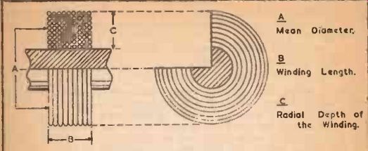
Fig. 5. Bank Wound Coil Dimensions.
When more than one coil is to be wound on a former-for example as in the case of the usual medium and long wave coil-it must be remembered that the two windings are connected in series with all the turns in the same direction of rotation so that when the shorting switch is opened (Fig. 2) the inductances are in series and will be added together. The long wave winding of such a coil, therefore, should have its calculated inductance reduced by the inductance of the medium wave coil so that the sum of the two inductances together equals the required long wave inductance.
Oscillator Coils
It is the writer's opinion that oscillator coils for superhets are too difficult to design where the tuning arrangements are to be ganged as in the commercial receiver. The complexity of the various calculations may be seen by reference to various designers' hand books, and even then it is often stated that experimental work on the proposed circuit is necessary to discover the adoptions and changes needed.
The difficulty lies in the tuning arrangements. If the main tuning circuit is to cover, say, from 200 to 500 meters-a range of 1.500 to 600 kHz the oscillator coil for an intermediate frequency of 460 kHz will be working between the points 1,960 to 1,060 kHz.
It will be seen that the ratios of maximum to minimum frequencies are different, being 1 to 2.5 for the tuning coil and 1 to 1.84 for the oscillator coil. The steady difference of 460 kHz will not be maintained by straight ganging, therefore, and to correct this a system of padding and tracking condensers is arranged in the oscillator circuit.
In amateur short-wave receivers, it is becoming usual to tune the oscillator quite independently of the aerial or H.F. circuits with a separate variable condenser, and this is probably the best way out of the difficulty for tracking can then be made 100% accurate over the whole dial. Using this method the oscillator coils can be calculated in the ordinary way.
Aerial Couplings
The signals from the aerial may he fed into the first tuned Circuit in a variety of ways which can be reduced to three main methods.
1. Aperiodic Coil Coupling.
2. Condenser Coupling.
3. Tap Coupling.
Almost all tuning coils are connected with one end earthed and the other feeding the grid of the valve (tube) and for convenience these are termed the "earthy" and "H.F." ends respectively.
For aperiodic coil coupling a small aerial coil is wound on the same former which holds the tuning or grid coil, the winding being near the earthy end of the grid coil. The number of turns depends on local conditions but 30 turns in either a single layer or bank wound should be satisfactory for medium and long wave coils. or one quarter of the grid -turns for other coils. The end of the winding nearest the grid coil is earthed, the aerial being taken either to the other end of the aerial coil or to taps which could be included at the tenth and twentieth turns. The aerial coil should be 0.5" from the H.F. end of the grid coil (Fig. 7e) and both grid and aerial cods are wound in the same direction.
Signals will be stronger although some selectivity will be sacrificed by using condenser coupling. In this method the aerial is connected to the H.F. end of the grid coil via a very small condenser--a ceramic trimmer type is suitable-and the capacity is varied for the best results.
Coil and condenser couplings can be combined to give a filter effect, a condenser in series with the earth lead from the coil being arranged to tune the aerial coil to the frequency of any interfering station.
On short and ultra short waves, condenser coupling can be used but the capacity must be very small indeed to minimize the aerial's damping effect on the circuits with consequent dead spots.
Coil coupling is better, a 3 or 5 turn coil being mounted near the H.F. end of the grid coil or between the grid and anode coils of a circuit such as the Franklin self oscillator. Whether the coils are former wound or self supporting the spacing between the grid and aerial coils should be varied to obtain the optimum position.
On these wavebands special aerials are often used together with twin feeders and in these cases the aerial coil is not connected to earth but has one feeder connected to each end.
Tap feeding will cause damping of the coil and will probably put ganged circuits out of alignment. It may be used on a simple circuit, however, and merely consists of various tappings taken from the grid coil to which the aerial may be connected. Alternatively the aerial may be taken to a variable capacitor of up to 300 picofarads capacity, the other terminal of the capacitor being taken to the tap. The nearer the tap is to the earthy end of the grid coil the less will be the damping imposed on the circuit and the greater the selectivity. Unfortunately sensitivity falls with increased selectivity. A tap at every tenth turn up to the center of the coil should give enough adjustment for any aerial.
Reaction Windings
Where reaction windings are to be used it is difficult to give , hard and fast rules. The type of circuit, the valve (tube), the anode voltage and the waveband covered all have their own effects on the oscillatory characteristics of the system. It may be said, however, that for controlled reaction as in Fig. 2 the best form for the coil to take is a small closely coupled winding rather than a large loose coupled coil.
This is so in short wave work particularly. where smooth reaction is essential, and in this case the reaction winding is made with wire of a gauge finer than that used far the grid coil, and sometimes even with resistance wire such as Manganin.
Coil sections are shown in Fig. 7 and it will be convenient to consider reaction arrangements for various wavebands.
Ultra Short Waves
Here the anode coil often becomes a part of the tuned circuit as in the Franklin oscillator or with Colpitt's circuits. and is of the same wire. shape and winding size as the grid coil, being indeed a continuation of the grid coil. Fig. 6a shows a very efficient ultra short wave receiving circuit where grid and anode coils are exactly similar, and regeneration depends on inter-electrode capacity coupling inside the valve (tube). Super-regeneration is included and the two larger coils for the feed leads superimpose an oscillation of much lower frequency (20 to 30 kHz.) on the ultra high frequency oscillation, thus bringing the circuit to the threshold condition where it is most sensitive and least selective. The net result is a hiss over the whole tuning range which reduces to silence or nearly so when a signal is received. Naturally the system cannot give good quality but for this type of work that is the least consideration. The super regeneration coils are tuned with condensers of about .006 mfd. capacity so that the inductance for bank wound coils to give the frequencies mentioned above can be calculated.
For an ultra short wave superhet the oscillator section might well be of the electron-coupled type as shown in Fig. 6d although the circuits of Fig. 2 or Fig. 6h are often used.
Between 10 and 180 meters the range is covered in bands as of 10-25. 18-60, and 50-180 meters or corresponding overlapping bands and reaction is usually applied by the throttle control circuit of Fig. 6b. For mains valve (tube)s, however, the circuit of Fig. 6c has much to recommend it for reaction is controlled by the potential on the screen of a tetrode and by feedback in the cathode coil which may conveniently be a short wave choke. There is of course no coupling between the grid coil and cathode inductance so that the grid and aerial coils may be simple. efficient windings on a small former.
Where an anode coil is used it may be arranged either as in Fig. 7c or 7d, being inter-wound with the grid coil in the latter case.
The wires must be insulated but must not touch in any case.
It is suggested that anode reaction coils are given one third the number of turns of the grid coil. the grid coil being tuned by a 100 picofarad capacitor and the throttle control a 300 picofarad capacitor, although as already mentioned individual circuits may need an adaption to these figures.
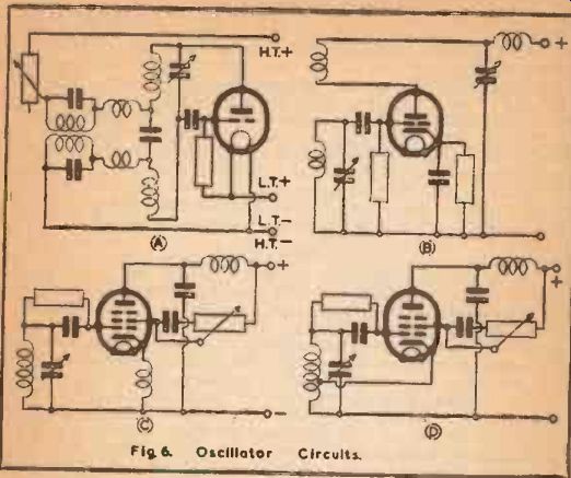
Fig. 6
Fig. 6d shows the electron coupled circuit where reaction depends on cathode feedback much as in Fig. 6c.
Medium and Long Wave Coils
In the majority of cases these will be wound on the same former in pairs as in Fig. 7e. The reaction winding has to serve for both wavebands and is wound between the grid coils preferably as a multilayer winding to save space. The best circuit to use is the throttle control system of Fig. 6b, usual values being 500 picofarad tuning capacitor, a 500 picofarad solid or air dielectric reaction condenser. 100-300 picofarad grid capacitor and a grid resistor which with modern practice has reduced its value from 5 megohms to 1 megohm or even less.
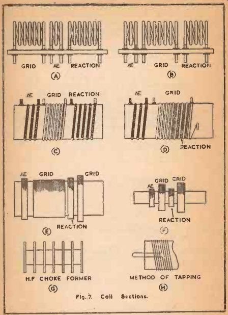
Fig. 7. Coil Sections.
As a general rule the reaction winding can have a quarter to a third of the total number of turns on the medium and long wave grid coils.
Fig. 7f shows a medium and long wave coil such as may be used for a midget or portable set. All the windings are multi-layer on 4" paxolin tubing.
Reaction coils must always be connected in their correct phase If a circuit fails to oscillate reversing the reaction coil leads generally corrects the fault.
Band Pass Units
Where two identical tuning circuits are coupled together the resonant frequency of each circuit changes slightly, one to either side of the original frequency, and if the original frequency was hen the new resonant frequencies are:
f f; =
VI -K and fa =
f V1 +K
…where K is the coupling factor. Thus a band of frequencies between fi and fi is passed, signals within the band being received strongly and those outside the band being cut off more sharply than with other forms of tuning.
A good band-width for normal conditions is 10,000 cycles and for "Bottom Capacity Coupling," the most simple system to arrange is as in (Fig. 4a).
../C1C1 K=
Cs r nd band -width is given by Bn fK.
Example 6.
Two matched coils are tuned by a 2 x 0.0005 mfd. capacitor to 600 meters (500,000 cycles) when the sections are fully meshed.
The band width at this point is to be 10,000 cycles, therefore as Bn = fK, 10,000 = 500.000 K and K = .02 VC1.C2
But K =
C3 ,/.0005 x .0005 so .02 =
C3
.0005
=-.
Cs
.0005 and Cs = -= .025 microfarads.
.02
Supposing, however, that when the value of the capacitors is reduced to .0001 microfarad the circuit now tunes to 300 meters (1.000,000 cycles) then 10,000 = 1,000,000 K or K is now only .01 and K becomes C2
.0001
.01 =
Cs and CI = .01 microfarad.
The band -width, therefore, will change over the tuning range with consequent varying selectivity.
In commercial practice C, may range from .01 to .5 microfarad.
The coils used for a Band Pass Unit must be similar in all respects so that perfect ganging is obtained, and should be in separate screening cans so that no magnetic coupling is possible between them, when capacity coupling is to be used.
I.F. Transformers
It will be seen that the I.F. Transformer is no more than a Band Pass Unit so arranged that the Intermediate Frequency is at the center of the band. In this case, however, the coils are coupled generally by mutual inductance although there is also a capacity coupling due to the capacity between the hank wound coils. R. E. Blakey (Radio and Telecommunication Engineers' Design Manual) points out that commercial practice makes the magnetic coupling oppose the capacity coupling by winding both coils in the same direction and connecting either the two starting or two finishing leads to anode and grid of the respective valve (tube)s.
Particular attention should be paid to making I.F. coils efficient with a high "Q", low loss tuning condensers being used with adequately sized circular screening cans. The main trouble in the construction of I.F. Transformers lies in the adjustment of the coupling between the coils which controls the bandwidth and thus the selectivity, and as these calculations depend on the value of the mutual inductance which is difficult to arrive at it is suggested that experimental methods will give quicker results.
Example 7.
An I.F. Transformer for 465 kHz. is required, both primary and secondary being tuned and identical.
First consider the tuning. The coil will have a self -capacity adding its effect to the capacity of the small tuning condenser so that if 100 picofarad is considered a satisfactory condenser to use the calculations for resonant frequency should be based on almost the maximum value of this condenser, say. 75 picofarad or .000075 microfarad. Then the capacity of coil and condenser will come well above this in practice, giving room for trimming adjustment either way. The condensers ideally would be of the ceramic mounted air-dielectric rotating type for these are more simple to build in and adjust than the screw operated trimmers, which have an additional drawback in the liability of the screw threads to slip.
The inductance required is discovered from:
f = 1,000,000 / 2 pi _/LC
where f is the frequency in cycles. pi is 3.14, L is the inductance in microhenrys and C is the capacity in microfarads.
For 465 kHz., then.
465,000 = 1,000,000 / 6.28 x _/.000075L
1,000,000 and .000075L =
465,000 x 6.28 and .0000751 = .3422
.342 x .342/.000075
or L = - 1,560 microhenrys.
This inductance may be made as already described in the example of a bank wound inductance, and mounted on r paxolin tubing. The transformer will require two such inductances.
Variable Selectivity
As already explained the band width passed by the I.F. Transformer will depend on the coupling factor-in this case the mutual inductance between the coils-and Fig. 8a shows the coils mounted on a wooden dowel with a push fit so that the coupling between them can be varied till the optimum position is found and then left, an increase in coupling (coils closer together) causing the band width to widen and vice versa.
For constantly variable selectivity, however, either a moving coil or tertiary winding can be employed. Fig. 8b shows one transformer coil arranged to rotate about a central axis about 1" from the other, the spindle being pivoted in the wall of the screening or on an internal framework. By using this method it is of course possible to gang a number of transformers by mounting them with the spindles in line and connected together by insulating tubing or rods.
Fig. 8c shows how the coupling and selectivity can be varied by a third coil mounted between the secondary and primary and possessing about one third of the number of turns on one of the main coils. Control is effected by a variable resistor of 5,000 ohms which is connected across this winding with its moving arm earthed.
As the resistance is reduced so coupling is reduced and the selectivity becomes greater.
When using these methods it is advised that one coil of the transformer is still mounted on a dowel with a push fit. The variable selectivity device is then arranged and clamped to give half of the total effect possible and the transformer response brought to its optimum setting by adjusting the coil on the dowel. The variable device will then give good control on either side of the mean position.
The condensers shown in the figures must be insulated from the screen or any other support, and have any earth leads returned directly to the chassis.
Coil Construction
When the inductance, method of winding and details of associated coils and condensers have been calculated and decided upon the type of former as already discussed is chosen and the coil wound upon it. Where bank wound coils are to be made it is suggested that a few commercial types should be inspected, they often have the wire laid on spirally in a wave winding which makes a very strong, self supporting coil and reduces the self capacity.
This is machine wound., however, and for hand winding it will probably be found sufficiently difficult to keep each layer even, tightly Packed without lumping or crossovers and with no break in the insulation. if a coil is to be tapped and is band wound on no account bare and solder the tapping lead so that the joint comes in the center of the layers. Instead draw out six inches or so of wire, fold the length into a long loop which is taken out through the cheek of the former, if used, and carry the wire back to continue the winding, anchoring the loop in place with the continuing turns.
Fig. 7h. The wire can then be bared and connected outside the coil with no risk of a breakdown in the insulation.
Only where wires are completely substantial, as in Ultra Short wave coils should they be used as the coil leads. Thinner wires should be taken to soldering tags and the simplest method of making and fixing these paxolin formers is to drill two small holes at the desired point i" apart, and to run a double loop of 18 S.W.G tinned copper wire through them. The winding wire is then soldered to the loop inside the former and carried to the starting point of the winding by the most direct route, being brought to the surface of the former through a third drill hole. This will give adequate anchorage and prevent slipping turns of wire.
When baring the ends of wire for soldering, silk and cotton coverings should be stripped off. not scraped, and enameled wire should be cleaned by dipping its end into methylated spirit and wiping with a rag. For soldering use cored solder, avoiding killed acid fluxes which will cause corrosion; there should be no chance of a dry or poor soldered joint at any place for bad joints make fault finding doubly difficult.
When the coils are wound it is very desirable to protect them from the effects of humidity and a method which will give them further strength and rigidity is to varnish or wax them. There will be a slight rise in self-capacity but this should not be troublesome.
The best varnish is polystyrene, which may be made from dissolving old or broken polystyrene formers in benzoic. Either immerse the coil in the varnish and allow it to drain very thoroughly or brush the varnish on with a soft brush, working it well into the layers of a bank wound coil. When the varnish is dry spacing turns can be stripped off and bobbin cheeks removed if desired.
Coils wound between paxolin washers, as in Fig. 7e, may be left untreated or protected by a layer of cellophane tape.
If the coils are given a protecting layer of wax instead of varnish it is more simple to be assured of thorough impregnation especially in the case of bank wound coils. Beeswax is melted down and then boiled, to make sure that any water contained in it is expelled and then the coil is dipped in the molten wax and allowed to remain until all the air bubbles are driven off and cease to rise.
Wooden formers or the dowels suggested for the I.F. Transformers should be boiled in the wax before use, once again remaining until air bubbles cease to rise.
When the wax has set the ca will be very firm but all surplus wax must be drained away.
Screening
Enclosing a coil in a screening can always result in some drop in efficiency together with a drop in inductance, these losses being vary serious if the can is not of an adequate size. It is possible however. to calculate the inductance drop due to a can so that when the coil is designed this loss can he allowed for by adding it to the correct inductance value of the coil.
A rough rule for keeping the "Q" of the coil high is to make the diameter of the can at least twice that of the coil; greater spacing would be beneficial but would make the apparatus bulky in most cases.
A. G. Bogle (bourn. I.E.E. Vol. 87) gives that for a coil mounted coaxially in a can of reasonably thick non-magnetic metal, where coil and can are cylindrical and the gap between the ends of the winding and the ends of the can is equal to or greater than flu gap between the sides of the coil and the sides of the can.
lig b2 Ln = L [1 - lig + 1.55 0
... where L2 is the inductance screened, L is the inductance unscreened, 1 is the length of the coil winding, g is the gap between the side of the coil and the side of the can (equal all round), a is the diameter of the can and b is the diameter of the coil, all measurements in inches, and the formula to hold lot frequencies of or over 100 kHz.
Example 8.
The coil of examples I and 3 is to be screened. L = 197 microhenrys, 1 = 2.5",'b = 2" and if the can is 4" in diameter g= 1" and a = 4".
Then 1 L,= 197 x 1 2.5
-+ 1:55 42 22 1
= 197 -- I 4.05
.625
[ 197 x .846 ,. 166.66 microhenrys, the new inductance.
Thus is the screened inductance is still required to be 19i microhenrys the percentage difference due to the screening effect must be added to the original inductance of the coil.
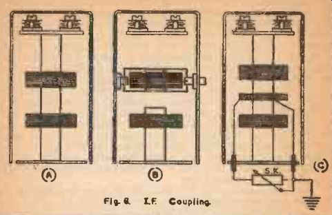
Fig. 8. IF Coupling
Testing Coils
Coils when wound may have several tests applied to them but for home construction it will be sufficient to make a simple continuity check with a battery and lamp or instrument and to measure inductance if a bridge is available or can be made. Where coils are to be matched. however, it is necessary to use a signal generator and valve (tube) voltmeter although the method is easy and gives good results.
Each coil is connected in turn across a small condenser and the output from the signal generator fed into the tuned circuit thus formed by connecting its leads across the coil. The voltage across the coil is measured by the valve (tube) voltmeter and when the signal generator is tuned through the resonant frequency the voltage rises sharply through a peak. Each coil is tested in this way and if the peak voltages occur at different settings of the generator that coil with the highest frequency setting has the lowest inductance and the other coils must be reduced to the same value. This is done by removing from them one turn of wire at a time until the resonant point of each coil falls on the same setting of the signal generator Naturally this method of adjustment should not be carried nevond narrow limits and two or three turns should be the maximum number removed. If a greater discrepancy between the coils the low inductance coil should he inspected for faulty winding or shorting turns.