Core Material.
It is essential for good reproduction of the low frequencies at low levels to have a material for the core which will maintain the inductance at very small values of A.C. magnetization. Ordinary transformer iron has a low initial permeability. Mumetal is the best material at present produced from this viewpoint. It has a higher permeability than other materials, but saturation occurs at a lower value, and hence it is not suitable where power is required.
The best shape for this type of transformer is shown in Fig. 11, together with full dimensions. Another type, having much larger winding window, has had considerable favor, but it will be realised that increasing the cross section of iron will reduce the turns necessary for any given impedance. For this reason the shape shown gives not only a wider frequency band, but also gives a more level response within that range, by reducing tendencies to L.F. and H.F. resonances.
The core stack should be 7/16th", so that the section is square.
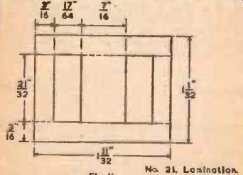
FIG 11.
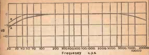
Fig. 12.
Turns and Ratio.
If the valve (tube) into which the transformer operates is a triode, a secondary composed of 4,000 turns of 44 S.W.G. enameled copper wire will give as good a step-up condition as any smaller gauge.
But if the valve (tube) following the transformer is a tetrode or pentode, the input capacity will be much smaller, and so further advantage can be gained by reducing the wire gauge, so that the secondary may consist of 6,000 turns of 46 S.W.G. enameled copper wire.
Fig. 12 shows the fonts of frequency response when the primary impedance referred to the secondary is 65,000 ohms in the case of the 4,000 turn winding, or 150,000 ohms in the case of the 6,000 turn winding. (These curves allow for a valve (tube) input capacity, including strays, but not that of the transformer winding. of 100-120 MMF in the first case, and 30-50 MMF in the second case.) At the low frequency end, curve A is for input transformers, or inter- valve (tube) transformers, where the coupling capacity is considerably greater than the value given for curve B. Curve B is for an inter-valve (tube) transformer in which the coupling capacity is N2 x 0.16 MF, where N is the transformer step-up ratio. If the value of coupling condenser is smaller than this, there will be a tendency to produce an L.F. resonance in the region of cut-off, which will need to be damped by the method shown later in this section, unless for some reason the resonance should be desirable.
The step-up may be increased by reducing the primary turns, which will increase the impedance referred to the secondary in proportion to the square of the increase in turns ratio. This will result in narrowing the frequency band from both ends. The whole high frequency cut-off curve will be reduced in frequency by the square of the increase in turns ratio. In the cases where curve A applies for the low frequency end, the whole cut-off curve will be raised in frequency by approximately the cube of the increase in turns ratio. In the case where curve B applies, the value of coupling condenser to give the same shaped cut-off will be reduced in pro portion to the cube of the increase in turns ratio, when the whole curve will be raised in frequency by the same ratio. These statements are only approximate. Mumetal has the peculiarity that the inductance of any given number of turns using a Mumetal core is reason ably constant below 50 cycles, but above that frequency gradually tends to vary inversely proportional to frequency, so that above about 600 cycles the law is such that the inductance has a constant reactance. Thus if the ratio is increased so that the cut-off begins above 600 cycles, then the effect will change from that of increasing the cut-off, to one of introducing further loss over the entire frequency. Otherwise stated further increase in step-up ratio will not result in further increased true step-up.
Primary Impedance
In the case of input transformers, the primary impedance is simply that of the device for which the input is matched-microphone, pick-up, etc. In the case of an inter- valve (tube) transformer, the primary impedance may be taken as the equivalent parallel resistance of the preceding valve (tube) anode impedance and its anode coupling resistance.
Resonances.
It is possible for a peak in the frequency response to appear due to resonance in the region of either the low frequency cut-off, the high frequency cut-off, or both. If the size recommended is used, the possibility of an H.F. resonance is greatly reduced, but use of a small value of coupling condenser may introduce an L.F. resonance.
With the older shaped core, necessitating many more turns for the same impedances, both types of resonance were more likely to appear.
With both types of resonance, the peak may be reduced either by increasing the primary impedance or by introducing a secondary shunt resistance in the form of a grid leak. The primary impedance can usually be increased enough merely by raising the value of anode resistance. If this cannot produce sufficient damping without going to too high a value, a resistance may be inserted in series with the coupling condenser, or the value of grid leak adjusted to bring about the desired response. With each of these methods, response at both ends of the scale will be reduced, so that they may be applied if there are two resonances, one at each end. If there is only a resonance at one end, and the other end does not require reduction, then different methods must be applied.
If there is a low frequency resonance but the high frequency cut-off does not need reduction, then a resistance connected across the primary of the transformer (after the coupling condenser, not from anode to earth), will reduce the resonance at the low frequency end, and at the same time have the effect of improving the high frequency response.
If there is a high frequency peak, but the low frequency response has none, then a resistance connected in series with the grid will reduce the high frequency peak without introducing greater loss at the low frequency end.
Example 13.
An input transformer is required to give the maximum step-up for speech only (2(X) cycle cut-off) to work into a pentode grid. Find the step-up that can be used from a microphone of 600 ohms impedance.
From the A curve, the 3 dB point is seen to be just above 30 cycles This means that the cut-off can be multiplied by about 6.4 to brine it to 200 cycles. From the tables the cube root of 6.4 is found to be about 1.85. and the square of 1.85 is about 3.4. Then the referred impedance can be about 3.4 x 150,000 ohms, or 500.000 ohms, The impedance gives a turns ratio of former will be:
1.
2.
500,000 step-up can be , or nearly 900/1. This 600 900, or 30/1. So the windings on the trans -
Secondary, 6,000 turns Primary. 200 turns.
Example 14.
A triode having an anode impedance of 2,500 ohms is used with an anode coupling resistance of 10,000 ohms. What step-up can be used to give the response of Fig. 12 with a secondary of 4,000 turns of 44E, and what coupling condenser should be used? The primary impedance is the effective impedance of 2,500 and 2,500 x 10,000 10,000 ohms in parallel or 2,000 ohms. This is to be 2,500 + 10,000 referred to the secondary as 65,000 ohms, so the impedance ratio 65,000 of the transformer is , or just over 30/1. This gives a turns 2,000 ratio of just over 5.5/1. The secondary turns are 4,000, so an appropriate primary will be about 700 turns. To give the response of curve B in Fig. 12, the coupling condenser should be 30 x 0.16 or 5 MF. Probably a 4 MF, being a standard value, will be adequate.
However, this value may be too large to be practical, in which case a smaller one, say 0.5 MF, may be used. A resistance of about 20.000 ohms across the primary will damp the resonance, and the cut-off will now be at about 50 cycles.
SECTION 7
Push -Pull Inter - Valve (tube) Transformers When an inter - valve (tube) transformer has to provide signal for the grids of two valve (tube)s in push-pull, it is essential that each valve (tube) should receive its signal identical in amplitude and in opposite phase to the other. For the lower and middle frequencies, accurate division of turns will secure this condition, but for the upper frequencies further precaution must be taken to maintain this balance.
A simple method enabling an ordinary inter - valve (tube) with only one secondary to be used, is that of connecting two equal resistances across the secondary in series and taking the center tap of these resistances to earth or grid bias. Then each end of the secondary is connected to one grid. This method suffers from the disadvantage that the capacity between each end of the secondary winding and earth is not equal, and so these two equal high resistances may be regarded as being shunted by unequal capacities, which, of course, upsets the balance at the high frequency end.
The better method is to wind two separate secondaries to that they are equally well coupled to the primary, and have as near as possible the same capacity from their "live" end to earth. On the size detailed in the previous section. this may be achieved by winding one secondary of 3,000 turns before the primary, and then the other secondary of 3,000 turns after the primary. The difference in winding capacity will not be great, and will in practice be much smaller than the input capacity of the valve (tube)s, which will thus help to reduce the effective inequality. The two ends of the secondaries adjacent to the primary should be connected together to form the center tap, while the extreme ends go to the grids.
As each grid is now only across one half as many turns, and the turns are rather better coupled to the primary, the input capacity per grid may be rather more than twice the figure given in SECTION 6 to obtain the same high frequency characteristic--i.e., about 70-120 MMF. Thus, the ratio may be calculated by making the impedance ratio from primary to the whole secondary such that the primary impedance is stepped up to about 150,000 ohms.
If push-pull feed back is being used, or separate grid returns for bias purposes, the two "inside" ends of the secondary may be brought out separately for the purpose.
In designing push-pull transformers on this size, it is necessary to make sure that a certain voltage limit is not exceeded, otherwise distortion will be quickly introduced.
A safe figure may be taken as 80 turns per volt at 50 cycles. This means that the total voltage across 6,000 turns should not exceed 75. If negative feedback is being used, do not forget to add the feedback voltage to the grid to grid voltage, as this will be the total voltage required across the trans former secondaries.
If this voltage limit is going to be exceeded, then a larger size is necessary.
If possible, a lamination size similar in shape to that of Fig. 11, but larger, should be chosen, and all the details multiplied up proportionately. The safe turns per volt will decrease as the cross sectional area of the core increases. Thus. if a i" stack of a size having a center limb width of *" is used, the area is 1" X. V% instead of 7/16th" x 7/16th" or about double. Therefore the safe turns per volt is reduced to about half, or 40. If 6.000 turns were still used for the secondary, the safe voltage at 50 cycles would be 6,000/40 = 150-twice the previous figure. At present the author knows of only one lamination manufacturer who has tools for such a size, and to date this size has not been produced in Mu-metal. A similar overall size is obtained by use of the lamination shown in Fig. 13, which is supplied in MU-metal.
On this shape, the safe turns per volt are the same as with the smeller size, because the cross-section of the center limb is the same.
So higher voltage can only be accommodated by increasing the turns.
Multiplication by 1.4. to 8,500. and using the same referred impedance, with a divided secondary, will give approximately the same results as those shown In Fig. 12. This gives a safe grid -to -grid voltage at 50 cycles of 105.
If step-up is increased beyond this point by simply increasing the secondary turns (thereby increasing the ratio), the cut-off at the top end of the scale will fall in the same way as shown for a corresponding increase in ratio in SECTION 6, but the L.F. cut-off will remain unchanged. If the safe voltage is increased increasing by increasing the primary and secondary turns proportionately (thereby maintain the same ratio), then the low frequency cutoff will be reduced to a lower frequency, and the high frequency cut-off will be reduced by a less amount, but it will progressively begin to show signs of peaking. This peak can be reduced by the methods outlined in SECTION 6.
Fig. 13.
Fig. 14.
Fig. 15.