When an inter-valve (tube) transformer has to provide signal for the grids of two valve (tube)s in push-pull, it is essential that each valve (tube) should receive its signal identical in amplitude and in opposite phase to the other. For the lower and middle frequencies, accurate division of turns will secure this condition, but for the upper frequencies further precaution must be taken to maintain this balance.
A simple method enabling an ordinary inter-valve (tube) with only one secondary to be used, is that of connecting two equal resistances across the secondary in series and taking the center tap of these resistances to earth or grid bias. Then each end of the secondary is connected to one grid. This method suffers from the disadvantage that the capacity between each end of the secondary winding and earth is not equal, and so these two equal high resistances may be regarded as being shunted by unequal capacities, which, of course, upsets the balance at the high frequency end.
The better method is to wind two separate secondaries to that they are equally well coupled to the primary, and have as near as possible the same capacity from their "live" end to earth. On the size detailed in the previous section. this may be achieved by winding one secondary of 3,000 turns before the primary, and then the other secondary of 3,000 turns after the primary. The difference in winding capacity will not be great, and will in practice be much smaller than the input capacity of the valve (tube)s, which will thus help to reduce the effective inequality. The two ends of the secondaries adjacent to the primary should be connected together to form the center tap, while the extreme ends go to the grids.
As each grid is now only across one half as many turns, and the turns are rather better coupled to the primary, the input capacity per grid may be rather more than twice the figure given in SECTION 6 to obtain the same high frequency characteristic--i.e., about 70-120 MMF. Thus, the ratio may be calculated by making the impedance ratio from primary to the whole secondary such that the primary impedance is stepped up to about 150,000 ohms.
If push-pull feed back is being used, or separate grid returns for bias purposes, the two "inside" ends of the secondary may be brought out separately for the purpose.
In designing push-pull transformers on this size, it is necessary to make sure that a certain voltage limit is not exceeded, otherwise distortion will be quickly introduced.
A safe figure may be taken as 80 turns per volt at 50 cycles. This means that the total voltage across 6,000 turns should not exceed 75. If negative feedback is being used, do not forget to add the feedback voltage to the grid to grid voltage, as this will be the total voltage required across the trans former secondaries.
If this voltage limit is going to be exceeded, then a larger size is necessary.
If possible, a lamination size similar in shape to that of Fig. 11, but larger, should be chosen, and all the details multiplied up proportionately. The safe turns per volt will decrease as the cross sectional area of the core increases. Thus. if a i" stack of a size having a center limb width of *" is used, the area is 1" X. 5/8" instead of 7/16th" x 7/16th" or about double. Therefore the safe turns per volt is reduced to about half, or 40. If 6.000 turns were still used for the secondary, the safe voltage at 50 cycles would be 6,000/40 = 150--twice the previous figure. At present the author knows of only one lamination manufacturer who has tools for such a size, and to date this size has not been produced in Mu-metal. A similar overall size is obtained by use of the lamination shown in Fig. 13, which is supplied in MU-metal.
On this shape, the safe turns per volt are the same as with the smeller size, because the cross-section of the center limb is the same.
So higher voltage can only be accommodated by increasing the turns.
Multiplication by 1.4. to 8,500. and using the same referred impedance, with a divided secondary, will give approximately the same results as those shown In Fig. 12. This gives a safe grid-to-grid voltage at 50 cycles of 105.
If step-up is increased beyond this point by simply increasing the secondary turns (thereby increasing the ratio), the cut-off at the top end of the scale will fall in the same way as shown for a corresponding increase in ratio in SECTION 6, but the L.F. cut-off will remain unchanged. If the safe voltage is increased increasing by increasing the primary and secondary turns proportionately (thereby maintain the same ratio), then the low frequency cutoff will be reduced to a lower frequency, and the high frequency cut-off will be reduced by a less amount, but it will progressively begin to show signs of peaking. This peak can be reduced by the methods outlined in SECTION 6.
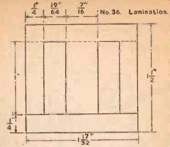
Fig. 13.

Fig. 14.
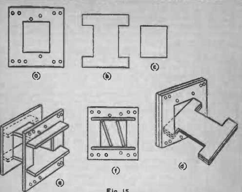
Fig. 15.