Turns Ratio.
This is comparatively simple to check, if there is available A.C. mains, two A.C. voltmeters, and a variety of odd resistances.
At least one of the voltmeters should be a high-grade multi -range instrument. The other may be any indicating instrument that will give a consistent indication when the same volts are applied. In this case, readings on the poorer instrument may be calibrated by comparing the two instruments in parallel on the same voltage, adjusting the voltage to various values by means of different arrangements of resistances.
It is important when checking turns ratio that an A.C. voltage no higher than that for which any given winding is designed shall be used. Having checked on this by calculation. readings can be taken of the voltage across the two windings, first by feeding a voltage into the primary and measuring the voltage on both primary and secondary simultaneously with the aid of both voltmeters, then by feeding a voltage into the secondary. The ratios of these two sets of readings can then be calculated. and if there is any discrepancy between them, the mean value may be taken as the correct one.
Frequency Response.
This requires more apparatus than the previous test. An audio oscillator is needed, together with some voltmeters whose performance at various frequencies besides 50 cycles is reliable. Also. the conditions under which the component is to operate must be simulated. That is, the primary must have the signal applied to it from an impedance equal to the one which it will have in practice, and the secondary must work into the same impedance as that for which it is intended.
If it is designed to operate with D.C. flowing in one winding. then this condition, too, must be reproduced in testing its response.
Transformers with no D.C. Components.
Fig. 16 shows a way in which components of the types detailed in Section V may be tested. The resistance between the primary voltmeter and the actual primary is equal to the equivalent source impedance. In the case of a push-pull output transformer (class Al it will be twice the anode impedance of each valve (tube). The resistance across the secondary is equal to the required load impedance at the secondary. It should be noted that the primary source impedance is not the same as the optimum load at the primary side. It may be more (as in the case of transformer to work with tetrodes or pentodes) or less (as in the case of transformer to work with triodes).
A frequency response may be taken by setting the voltage at the primary voltmeter to the same reading. and then noting the reading on the secondary voltmeter. If the readings on the secondary voltmeter are plotted against frequency on graph paper. a frequency response will be obtained.
In the case of loudspeaker transformers. the source impedance should be that of the output valve (tube). as it will he referred to the primary of this transformer.
Example 15.
An amplifier has output valve (tube)s having an anode impedance of 2.500 ohms each, and an optimum load of 8,000 ohms anode to anode. This is matched to 250 ohms. From this it is distributed to several speakers. One of these is intended to take one -eighth of the output.
8,000 The output transformer has a step-down of or 32/1 impedance 250 ratio. Thus, the source impedance at the secondary will be 2,500 -= 78 ohms. The share of this applicable to a speaker taking 32 one -eighth of the power will be 8 x 78, or 625 ohms, while the load impedance referred to this primary, due to its own speaker load on the secondary, will be 8 x 250. or 2,000 ohms.
Parallel Fed Inter-valve (tube) Transformers.
The primary source impedance for these may be simulated in the same way, but the secondary must also be arranged to have the same loading as in practice. This may be only at the grid or grids of the next stage. In this case, the meter itself would impose a load which would falsify the reading. So the secondary must be connected to valve (tube) grid, or grids, in the same way as it will be in practice, and the signal voltage in the anode circuit can be read by resistance capacity coupling to a voltmeter.
Transformers with D.C. Flowing.
The simplest method of testing the frequency response is to set up the actual operating conditions. A voltmeter measuring the volts applied to the grid of the valve (tube) into whose anode the primary of the transformer is connected is set to the same reading at different frequencies. The secondary reading is taken in the same way as before, according to whether it is an output or inter-valve (tube) transformer.
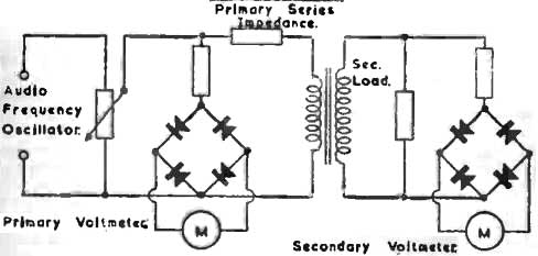
Fig 16.
Air Gap Adjustment of Chokes and Transformers carrying D.C.
A simple method of doing this is to set up a full -wave rectifier circuit with no smoothing. Across this, connect the component to be tested in series with a resistance to limit the D.C. to its rated value.
If, on measuring the A.C. component across the choke, this is more than required in practice, a suitable reservoir condenser should be applied across the supply to reduce it to a practical value. Check that the D.C. flowing is correct, as altering the reservoir condenser alters the output of a rectifier. Having ascertained that D.C. flowing and A.C. across are correct, connect the A.C. voltmeter in series with a D.C. blocking condenser across the resistance in series with the choke, and adjust the gap. The highest inductance will be when the voltmeter across the resistance shows the lowest reading.
Winding Insulation.
The insulation between windings and between each winding and earth should he tested with a suitable "flash test" device. This is simply a fairly high voltage (higher than that which the insulation must stand in practice), either A.C. or D.C. In series with the supply on one side is a high resistance, sufficient to limit a short-circuit current to about 5 mA., and a neon bulb. The other side is connected to an earth plate on which the component can be placed for test.
To the high potential side is connected an insulated test prod. The usual procedure for a transformer would be as follows: Earth secondary with a lead and apply test prod to primary; earth primary with lead and apply test prod to secondary. The neon should not light in either case. Finally, to check the tester connection, the prod may touch the earth plate, when the neon should light.
In the case of a choke, of course, the component is simply placed on the earth plate and the prod applied to the winding terminals.
Shorted Turns Tester.
A useful adjunct to the regular winder is some device to detect the existence of shorted turns before the component is cored up, thus saving time if the component should prove faulty.
A simple method of constructing such an instrument is to make up a simple triode feed-back oscillator of any type (to give, say, 400 cycles), using for the coil an inductance, wound on an iron core of similar or slightly cross-section to the components to be tested.
Instead of making this inductance in the usual way of an iron -cored inductance, it is so arranged that the core is open and can have the coil to be tested placed over the core adjacent to the inductance coil of the oscillator, which is arranged so that it can be adjusted by means of a variable bias control, so that it only just operates.
Under this condition, if the coil applied for test has any shorted turns, then the oscillation will either stop, or be greatly reduced in amplitude. On the other hand. self-capacity in the coil applied will only alter the frequency slightly.