Transformers may be regarded either as impedance or voltage matching devices, and when designing power transformers it is more convenient to consider the voltage ratios.
Transformers for power supplies consist of two coils, or sets of coils, wound on an iron core to assist the coupling between them and thus improve their mutual inductance. Power from the A.C. mains is supplied to one coil or set of coils and the magnetic flux set up in the iron core and around the coil induces currents in the second set of coils, the voltages across these coils being either higher (step up) or lower (step down) than the voltage supplied.
The coil to which power is fed is known as the primary, those from which power is taken are known as secondaries, and in radio power transformers of 'both step up end step down windings.
The size of each winding bears a very definite relationship to the power supplied to or drawn from it, the number of turns controlling the voltage and the resistance, expressed as the diameter of the wire, controlling the current.
The number of turns varies inversely as the size of the core.
The core is built up of thin sheets of iron in the form known as a laminated core, and this is a method used in practically all A.C. apparatus. Clearly the rapidly varying magnetic flux will induce currents in the core as well as in the windings around it and if the core were one mass of metal with a very low resistance the current so induced would be exceedingly high. It is necessary therefore to increase the electrical resistance of the core which can only be done as described, by splitting it into thin sheets and insulating each sheet from the next. Eddy currents will still flow but the total loss of power so caused will be far less than it would otherwise have been.
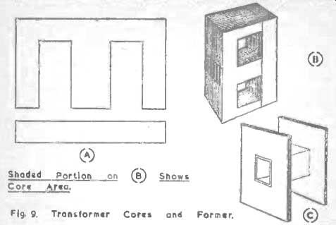
Fig. 9. Transformer Cores and Former.
Laminations are insulated in several ways-by chemical treatment of the metal surface, by varnish, by very thin cemented paper-and there are two main shapes of laminations, the E and I type and the T and U type, both sets giving a three legged core (Fig. 9a).
When the laminations are being inserted into the finished coils on their former they must he alternated, that is an E must go in from the left with an I from the right then an I from the left and an E from the right and so on, the laminations being brought into tight contact with no air gaps.
The cross sectional area of the core, Fig. 9b. is chosen from the formula given by The Radio Designers' Handbook, where A = - 5.58 where W is the volt-amperes output, and A is the cross section area in square inches.
Example 1.
A transformer is to supply 300 volts 100 mA's. 4 volts 2 A. and 4 volts 4 A.
The total output, therefore, is 100 300 X -+ 4 x 2 + 4 X 4 1,000 = 30 + 8 + 16 = 54.
54
Therefore A = - or 1.3 square inches is the necessary core area 5.58 The formula connecting the number of turns in a winding with a given voltage, size of core, frequency and flux density is
E_ 4.44xFXHXNXA / 100,000,000
... where E is the voltage supplied to or supplied by the winding, F the mains frequency. H is the number of lines of magnetic flux per square inch in the iron and A is the cross sectional area of the core
If E is allowed to equal I then the calculation will give the number of turns per volt for any winding on that core.
It is supposed that often transformers will be rewound using materials to hand, and in this case the characteristics of the iron will not be known. The best compromise in such conditions is to let H equal 60,000 lines per square inch, a figure at which many power transformers are run, although if winding space and other conditions permit this may be reduced to 50,000 lines. A, it must be remembered, is built up of laminated sheets which have insulation on one side at least so that the actual magnetic area will be only 90% or so of the geometrical area. This measured area, then, should be reduced by 10% for the calculation. The shape of the core must be well proportioned, each outer limb having half the width of the middle limb on which all the windings arc placed in layers, thus occupying the window space "a x b" of Fig. 9a. The general order of the windings is primary inside, nearest the limb, the H.T. secondary and the heater windings outside, of which there arc usually at least two, one to supply the rectifier heater and one for the valve (tube) heaters of the receiver or apparatus.
The regulation of the transformer is very important-that is the virtue of its having only a small output voltage variation with varying current loads-and depends to a great extent on the iron of the core, the shape of the core and the filling of the window space with windings, there being no large gap between the last layers of wire and the outside limbs. The core must be large enough and the wire diameter fully adequate to handle the loads expected.
The main losses in a transformer are "iron" and "copper' losses; those watts lost due to eddy currents and the purely magnetizing effect on the core, and the watts lost due to the currents flowing in the resistances of the windings. Theoretical transformer design requires these losses to be equal when the transformer will be at its most efficient working level, but for the purposes of small transformer design it will be sufficient to base all calculations on a theoretical efficiency of 80% instead of 90% or so which, with care, will be obtained. These losses will be dissipated as heat and any transformer which heats up in working to anything but a small degree is inefficient and wasteful. Power is being lost, regulation will be poor and insulation will be subjected to the most undesirable strains. A good transformer will work for hours with a temperature rise which can scarcely be observed by touch.
The windings are usually on a former, Fig. 9c, a tube which will fit the core tightly with end cheeks to clear the window space, and through which the leads pass. Such a former can be made of stiff cardboard well shellacked, or of thin paxolin. Cardboard is quite suitable for ordinary voltages; the tube is first made to fit the core and the end cheeks are fitted, then the whole is well varnished and allowed to set hard. It will perhaps be best to follow the design and construction of a specimen transformer throughout.
Example 2.
A transformer is to be made with the specification: Primary to be tapped to 210, 230, 250 volts, Secondaries. 350-0-350 volts, 120 mA's., 6.3 volts 3 A. and 5 volts 2 A.
The watts ratings, therefore, are:
350 x 120 mA's (only half the H.T. winding supplies current at one time --=
6.3 X 3 =
5 X 2 =
giving an output total wattage of or, say 71 watts.
42 watts.
18.9 watts.
10 watts.
70.9 watts.
71
The cross sectional area of the core should be at least A = 5.58 or 1.5 square inches. and assuming an efficiency of 80%. which should certainly be bettered in practice, the input wattage is therefore
100 71 X - or 88.7 watts.
80
At a working voltage of 230. therefore (the usual mains voltage) 88.7 the primary will take -- amps. or .4 amps, nearly, and the wire 230 must he chosen to carry this current safely. The question of insulation enters here.
Commercial transformers, as inspection will show. arc most often wound with enameled wire. but conditions are different from those obtaining for home construction. The commercial transformer is machine wound so that the wire can he, and generally is slightly spaced between turns so that there is no rubbing of the enamel, whilst the wire tension can be more accurately controlled. For amateur construction enameled wire can be used but on no account should it be wire taken from old coils or transformers. It must be new and every precaution must he taken to ensure the covering is not cracked, kinked or rubbed for a breakdown in insulation in any winding renders the whole transformer useless.
Probably the best plan is to use enameled wire with the added protection of a single silk covering for the heavier primary winding.
A suitable core is now chosen, one with an area of 2 square inches (reducing to an electrical area of 1.8 sq. ins.) being before the writer.
The turns per volt formula becomes, then, 1 - 4.44 x 50 x 60.000 x N x 1.8 100.000.000 but if desired a factor can be produced relating to all transformers where H is taken as 60.000 by leaving out the terms N and A.
This factor, obviously. for 50 cycle mains, is 4.44 x 50 x 60,000 1= X AN 100.000,000 = .1332 AN so that the formula for this transformer becomes
1 = .1332 x 1.8 X N = .24N and N = - or 4.2 turns per volt.
.24
The windings can all be calculated, then, the primary having 250 x 4.2 = 1,050 turns tapped at 966 and 882 turns, the secondary has 700 X 4.2 = 2,940 turns, center tapped, the valve (tube) heater secondary has 6.3 X 4.2 = 26.5 turns and the rectifier secondary has 5 x 4.2 = 21 turns.
The size of wire, as already shown, affects the current flowing in the winding, and for this type of transformer the gauge may be chosen on the basis of a current flow of 2,000 amps per square inch.
The primary draws .4 amps. so from the wire table it will be seen that S.W.G. 26 enam. and single silk will be suitable; for the H.T. secondary enameled wire with an interleaving of thin waxed paper between each layer will be used, and to carry the 129 mA's S.W.G. 34 will be suitable.
S.W.G. 18, enameled, will suit both heater windings, and to make up losses one extra turn is usually added to the calculated figures for these two coils.
It is now necessary to pay some attention to mechanical details and to check over the dimensions of the former. The size of the window space. a x b, as shown in Fig. 9a, is I*" x ir and the former may he supposed to be made of one -eighth material, card or paxolin. This will reduce the available space in three directions, leaving the depth of the window one inch and the length one and five -eighths inches. The space taken by each winding must now be calculated.
The Primary S.W.G. 26 enam. and single silk winds 48 turns to the inch, so that the former will take 48 x 1,1, turns per layer, or 78 turns.
1,050
The number of layers will be or 14 layers and the height will 78 therefore he -I".
S.W.G. 34 enam. layer will contain 100 2,940 be or 19 layers, 162 The H.T. Secondary wire winds 100 turns per inch so that each x 11 or 162 turns. The number of layers will and these will be one -fifth inch high.
Heater Secondaries S.W.G. 18 enam. wire winds 19.7 turns per inch so that one layer will contain 19.7 X 1 or 32 turns so that each heater winding will fit into a layer comfortably, and the whole wire height of the two windings together will be under r.
The total height of the wire alone, then, is + 1/5th + I or inch, leaving inch space for insulation.
When the former is made, shellacked and perfectly hard the cheeks may be drilled for the leads using the figures above as guides or the holes may be made as the work progresses providing there is no chance whatever of damaging the wire insulation in any way.
The primary is wound first, the wire being cleaned properly with spirit, not by scraping, and having a flexible lead soldered to it.
The soldered joint must be perfectly smooth with no sharp points or projecting wire ends, and it is then covered with insulating sleeving which carries the flex lead through the cheek. The wire is then wound either by hand or by a simple winder, which is much to he preferred. All that is needed is a spindle turning in end plates or bearings. a handle at one end. Two adjustable cheeks arc then mounted on the spindle to grip the former tightly, the spindle (which might well be a long screw threaded rod) passing through the center hole of the former. The former is then rotated with the right hand, the wire being fed off its reel and tensioned evenly with the left. The turns should be laid evenly side by side and counted as they are put on. in the absence, as is likely, of a mechanical counter it is convenient to mark every twenty turns on a sheet of paper.
The primary winding is not interleaved so that when the of one layer is readied the wire is wound straight back on itself and tension must not be over tight for each corner of the former presents a sharp right angle bend to the wire whilst the lower turns have to sustain the considerable strain of all those windings above them.
It is necessary to understand the effect of one short-circuiting turn in any winding. It would consist of a very low resistance loop in which, therefore, a very high current would he induced, this causing heating and consequent burning of the insulation on ad joining turns of wire, whilst the extra load reflected into the primary might cause that winding to be overloaded to the fusing point.
It must be realised that the current flowing in the primary depends entirely on the load being drawn from the secondaries: with the secondaries disconnected the only current flowing in the primary is the small core magnetizing current and the winding acts as a choke.
The taps for the various primary voltages can be taken out in the same manner as the taps on coils. by drawing out a loop of wire and returning the wire to the next turn without any breaks or joins, or a flex lead may be soldered to the winding at the correct turn and well insulated. Whenever possible taps should be arranged to fall at the end of a layer so that they may be passed straight through the former cheek. If, however, they have to pass over several turns the insulation must be perfect and on no account must unevenness of winding be allowed in the next layers. Any bump in the center of the coil will be magnified in the later layers with a corresponding strain on wire and insulation.
When the primary is finished, and a flex lead soldered to the last turn, the winding must be insulated from the following coils.
The best material is Empire Cloth interwoven with glass fibers and known under such names as Glaccire but plain Empire Cloth may be used. Every part of the primary must be covered, the insulation being carried up snugly to the former cheeks.
Many transformers have an electrostatic screen wound over the primary to prevent interference from the mains being induced into the secondaries. It consists simply of one layer of fine insulated wire-S.W.G. 34 enam, for example, one end of the wire being anchored internally and the other brought out through insulating sleeving. The end brought out is earthed to the receiver or other apparatus worked from the transformer. Naturally just as much attention must be paid to the insulation of the screen as of any other winding; no load is taken from it as only one end has a connection but shorting turns would give rise to the same heavy overloads mentioned above.
If the screen is included another layer of Empire Cloth is wound over it, giving a smooth, even base for the H.T. winding. Again a flex lead is soldered to the start of the coil and insulated but in this winding a sheet of thin paper is interleaved between each laver of wire. Excellent paper for this purpose can be obtained by stripping down an old paper condenser of the Mansbridge type, any punctured parts of the paper being discarded. On each wire layer one turn of paper is wound, fitting tight up the cheeks, and the wire is wound back over it to form the next layer.
At the center tap a flex lead is soldered to the wire and anchored firmly in the coil. the flex being taken through the cheek and the joint, as before, being perfectly smooth and insulated. When the H.T. winding is finished another layer of Empire Cloth or Glassite is laid over it and the valve (tube) heater winding made, the commencing lead through one cheek and the finishing lead through the other.
A layer of Empire Cloth or Glassite separates it from the last winding, that for the rectifier heater which is put on in the same way.
Study of any power pack will show that the full H.T. voltage is established between the H.T. and rectifier heater windings and the insulation between them must be perfect. Any breakdown here immediately ruin both transformer and rectifier valve (tube)s.
When the former is wound it is given a last covering of cloth and the laminations are inserted into the center aperture in order as already explained. The stampings must he inserted carefully for it may be possible to run a sharp edge or corner into and through the former material, cutting or scraping the primary winding.
The laminations must be damped into a solid mass with wooden or metal damps which can also be drilled to provide fixing holes far bolting the transformer to its chassis.
Testing
The first tests to be given the transformer are continuity and insulations checks, these being performed with a neon lamp worked from the A.C. mains. One mains lead is taken to the metal core of the transformer and the other, through the neon lamp, to each lead from the windings in turn. Any lighting of the lamp indicates a short circuit from a winding to the core which must be rectified.
The next test is to check the insulation between the windings; transfer the lead from the core to the common primary wire and test the screen and secondary leads in turn with the neon lamp.
transferring the mains lead from the primary to each secondary in turn as the test progresses.
Again, any lighting of the lamp indicates a short circuit, but actually any short circuits so discovered would be due to very careless workmanship and are unlikely.
Finally the continuity of each winding is checked with the neon lamp, connecting it across each coil in turn, not forgetting the tappings, when the lamp should light.
If a small megger is available really valuable insulation tests can be made but care must be used to choose a voltage below any breakdown voltage calculated for the insulation used. However, as the peak voltage across the H.T. secondary of the transformer described would be almost 1,000 volts the transformer should certainly show a resistance of many megohms at 2,000 volts between windings.
When the transformer has been checked for insulation and continuity, its voltage ratios can be checked. The primary is connected through the suitable tapping to the A.C. mains, with all the secondary leads well separated so that no two can short-circuit together.
Never check secondaries by touching the leads together to produce a spark - results are spectacular but impose an unnatural strain on the primary and should the transformer have been wound to close limits the high currents flowing will probably fuse a winding.
Switch on with the primary only in circuit. After a slight thump or click there should be very little hum from the core, and any appreciable noise indicates loose laminations which must be tightened.
Let the primary run alone for ten minutes and check for warming up. Any temperature rise indicates either a totally incorrect winding size or shorting turns in any one of the windings.
In either case connect an A.C. voltmeter across each secondary in turn, and note the voltages obtained from each. If they are all low, and the transformer is heating up, it is likely that there are shorting turns in the primary. If one voltage is low there arc probably shorting turns in that secondary alone. Any winding with shorting turns must be rewound but if the work has been done properly and good wire used there is very little reason for this fault to occur.
Check the voltage on the H.T. secondary from the center tap to either end of the winding-there should be no difference in the readings, or at most one of only one or two volts. The heater winding voltages will be a little high but when the load is applied they will fall to their correct value.
If the voltages arc correct the transformer may be finished and coupled up, but a power test is advisable. For this, non-inductive resistors of adequate watts ratings must be used in the following manner The H.T. secondary supplies 350 volts at 120 mA's or disregarding the center tap, 700 volts at 60 mA's. This is a wattage 700 X 1,000 of 42, the resistance needed being R = or 11,666 ohms 60 which might well be made up of lamps whilst the L.T. windings can be tested on load using a resistor of 20 watts rating, 2.1 ohms for the valve (tube) heaters winding and one of 10 watts, 2.5 ohms for the rectifier winding, or, of course, the actual valve (tube) heaters to be used.
The test should run for an hour at least and the rise of temperature of the transformer tested-in commercial practice it might rise by 40° centigrade, but this should be bettered.
When the testing is completed the transformer can be finished.
If the core is clamped satisfactorily and the transformer is to be permanently installed nothing more need be done but if the trans former is to be used for experimental work the leads should not be used for direct connections but should be taken to terminals, mounted on paxolin in the form of a strip secured by two of the clamping bolts.
If the transformer can be mounted in an iron case or can, any stray fields which might give rise to hum can be suppressed. The old case of a choke or transformer could be used or even a heavy tin. In this case the leads should be brought out through insulating bushings or the terminal strip should be well insulated. The case or can should not be allowed to touch the winding at any point, both to assist in insulation and also to allow air to circulate freely for the purposes of ventilation.
In some cases the most tiresome and painstaking work, that of winding the H.T. secondary coil, can be avoided. The transformer can be made on a proportionately smaller core with primary and secondary windings to feed the valve (tube) and rectifier heaters, the H.T. being drawn straight from the mains by using the rectifier as a half-wave device (Fig. 10b). This system is used extensively in television design.
The operation of the power pack as a whole may here be considered, with reference to Fig. 10a, where the transformer just described is shown in its circuit. The H.T. secondary has been wound to give a R.M.S. voltage of 350 which means that the peak voltage will be 350 X 1.414 (peak value of a sinusoidal wave).
Thus the rectifier anodes will have peak voltages of 495 volts, the whole winding having a peak voltage across it of 990 volts and even after the voltage drop due to the rectifier is allowed for the capacitor. A, has a voltage across it well in excess of 350 volts -- probably 450 volts. This explains why the voltage rating for this capacitor is necessarily high; a 350 volt working component would soon fail in this position.
The actual value of the condenser in microfarads is more or less of a compromise for the final output voltage of the power pack depends to a great extent on the size of the reservoir. If it were to be omitted the output voltage would be very low and as it rises in capacity so the output voltage rises towards the peak value. Before the peak voltage is reached, however, the condenser is excessively large (and expensive), but moreover, it would be drawing very heavy currents from the rectifier valve (tube) on each surge or peak of the cycle and the valve (tube) would soon lose its emission.
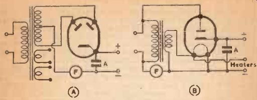
Fig. 10.
Valuable protection to the rectifier and transformer can be given by inserting simple fuses in the circuit as shown in Fig. 10.
They can be of the flash lamp bulb type, with a current rating to suit the load to be taken from the power pack with extra provision for any surges that might occur as the condenser charges up.
High Voltage Transformers
It is unlikely that the amateur will attempt the task of winding a High Voltage Transformer such as would be used to supply a large cathode ray tube, but a few points of High Voltage practice might be touched upon.
Firstly, the peak inverse voltage across a typical television transformer might reach as high as 10,000 volts, so that great care is essential during testing to see that no risk of touching any live circuit is taken.
Secondly, the positive side of such a power pack is usually earthed, so that strain is placed on insulation in many ways. For example the primary of the transformer might easily he earthed via the mains; in such a case the end of the secondary nearest the primary would be the earthed end, thus preventing a large potential difference directly across the insulation separating the windings.
Thirdly air insulation is often relied upon. At high voltages a trace of moisture upon an insulating surface might give rise to sparking or arcing which, while slight at first would rapidly become something approaching a short circuit. For this reason the layers of the secondary are not carried to the end cheeks of the former and as the winding grows outward from the center the layers are made shorter, giving a pyramid or stepped effect. In this way. as the potential above earth rises through the winding so does the distance between any earthed object and the winding increase.
Fourthly, the potential difference between the rectifier heater winding and the H.T. winding makes it necessary to have perfect insulation between the windings, a separate heater transformer helping in this respect. Metal rectifiers give very good results for cathode ray tube power supplies.