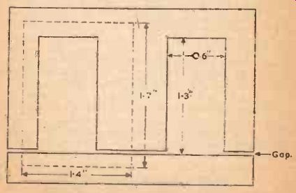
Fig. 11. Core for L F Choke.
The Low Frequency Choke is used in the power pack to filter out hum from the current supply, for inter- valve (tube) coupling and in various forms of input and output circuits. Slightly different methods of construction are used dependent upon whether the choke is to carry direct current in the winding as well as A.C.; in a power pack for example, D.C. is flowing whilst in a parallel fed inter- valve (tube) coupling D.C. would be excluded by a blocking condenser.
The effect of D.C. in the winding is to decrease the incremental permeability of the core material-in practice a laminated core is used as in the transformer-so that the iron saturates more rapidly and the inductance of the choke is lowered. This inductance loss can only be partially countered by arranging to have a small air gap between the sets of laminations in the assembled core.
For chokes carrying A.C. alone, therefore, the laminations are interleaved I are those in a transformer, but for a choke carrying D.C. and A.C. the laminations are assembled with the two sets of stampings one on each side--that is all the E's on one side and all the Ts opposite (or all T's together opposite all U's, whichever type of stamping is used), and it will be seen that in the core assembled in this manner there will be three air gaps, one at the end of each limb (Fig. 11). So far as the magnetic circuit is concerned even a tightly clamped butt joint acts as a small air gap, and for correspondingly larger air gaps a piece of thin tissue paper may be inserted between the end of each limb and the opposite laminations.
The calculation of the correct air gap for any single case is rather involved, however, and it is recommended that for mixed A.C. and D.C. operation the gap should be decided upon by experiment. As a rough guide it may be said that the close butt joint will do for currents of 5 or even 10 milliamps but for higher currents the gap must be widened by inserting a .0005" sheet of tissue or more.
Chokes for Alternating Current Only
These are chokes as used for inter-valve (tube) coupling, tone control, bass boosting, resonant circuits and audio oscillators, wherever the current feed to the valve (tube) is "shunted". The inductance of the choke is given by:
L = 3.2 X N^2 x µ x A / 1 x 100,000,000
... where L is the inductance in henrys, N is the number of turns of wire, g is the incremental A.C. permeability of the iron core material. A is the cross sectional area of the winding limb in square inches and 1 is the length of the magnetic path in inches.
A safe figure to use for u is 1,000 unless greater information about the core material is available, and 1 is measured directly from the laminations. A well -shaped core has the two outer legs only half the width of the inner or winding leg so that the magnetic path is split equally into two, and the length, 1, to be measured is the center line of ONE. of these two paths as shown by the dotted line in Fig. 11.
Example 1.
A choke to possess an inductance of 100 henrys is to be wound on the core of Fig. 11, the dimensions being as shown.
Calculate the number of turns and the size of wire.
I is measured on the core along the path shown and is 6.2 inches. The area of the winding limb is .3" x 1" or .8 square inches, and as the permeability has been taken as a low figure there is no real need for the 10% allowance to compensate for the thickness of the lamination insulation. The formula becomes, then,
100 = 3.2 x NC x 1,000 X .8 / 6.2 x 100.000,000
or N^2 = 24218750
and N = 4.920 turns nearly, say 5,000 turns.
The winding space is .6" x 1.3" and allowing .1" each way for a former with end cheeks this reduces to an area of .5" X 1.1" or .55 square inches, so wire must be used which will wind - 55 X 5.000 turns per square inch or 9.090 turns per sq inch. Reference to the wire tables shows that S.W.G. 34 enam. winds 10,000 turns per square inch which gives a little room for unevenness in winding.
The choke is finished in the same way as a transformer, with a tightly clamped core and a tape or cloth binding to protect the wire. No provision has here been made for interleaving the windings with paper as it is unlikely that any really dangerous voltage would be set up in such a choke.
Chokes for Mixed Currents
Where the choke is to carry D.C. as well as A.C. it will scarcely be possible to wind such a high inductance (should it be needed) on such a small core unless the D.C. component is practically negligible. In the first place the wire would need to be of a heavier gauge to carry the current as well as to reduce the D.C. resistance to as low a figure as possible. For example, it may he necessary to use a choke as the anode load for a valve (tube) for the reason that a suitable resistance load reduces the anode voltage to too low a figure.
The choke will still present a high impedance to the A.C. signal hut the D.C. resistance must be low or otherwise the whole purpose of the choke will be defeated. This means a thicker gauge of wire and therefore a larger core, for the number of turns must still be high to maintain the inductance and therefore the impedance to the signal. The simplest way out of the difficulty is to measure the winding space of the core to be used and choose a gauge of wire which when wound to fill the space will give a D.C. resistance suitable for the permitted voltage drop. This may be done by taking the length of an average turn on the winding limb, multiplying the number of turns given by the wire table by this length to find the whole length of wire in the winding, and then to check the resistance of this length in the wire tables.
The length of the average turn is, of course, the average of the length of the first and last turns on the winding and may be measured on the cheek of the core supposing the average turn to be geometrically situated at half the winding depth.
Smoothing chokes also may be wound in this way. Choose a suitable core with a cross sectional area of at least 1 square inch and a window space of at least 2 square inches and decide from the wire tables the gauge of wire which will carry the maximum current safely, using a current density of 1,500 or 2,000 amperes per square inch. Enameled wire is suitable for the winding and again the layers should not need to be interleaved, the space which would be used by the paper being of greater value if filled with wire.
The gap can be adjusted experimentally by allowing the choke to supply filtered D.C. to a sensitive receiver or amplifier. The core clamping bolts are loosened just sufficiently to allow the sets or laminations to he moved and the space between them is gradually opened until the hum in the loudspeaker, with no signals and the gain control right out, is at a minimum. The gap can then be set with a paper or very thin fiber packing and the core re-clamped.
The testing of insulation and general performance of the choke can be modeled on the lines described in section 4.