The circuitry used to extract the luminance and chrominance information from the composite video signal has been explained in Sections 2, and 5 of this guide. From these discussions, we learn that there are four video inputs to the color CRT:
(1) the luminance, or Y, signal which contains only brightness information; (2) the R-Y signal containing, essentially, only the red information without any brightness information, (3) the B-Y signal containing the blue information, and (4) the G-Y signal which contains the green information only.
It is customary to assign a notation of polarity to each of the last three of these signals. Thus we have the quantities (R-Y),-(B-Y), and-(G-Y) as well as their positive counterparts expressed above. These arbitrary designations can become confusing when considering the operation of the CRT itself since a specific gun, red for instance, conducts even when a (R Y) signal is fed to its grid.
Actually, the quantity 0 (R-Y) is defined as the amount of conduction of the red gun which, when the G-Y and B-Y signals are also at zero level, will produce reference white. Stated another way, zero levels of R Y, B-Y and G-Y are present during b-w reception.
Negative R Y, B Y, or G-Y refers to an amount of conduction of the specific gun which is less than that which is required to produce reference white.
Notice that the conduction of a specific gun is not entirely dependent on the color-difference signal fed to its grid. Conduction is determined by the grid-to-cathode voltage of the gun, and since the cathode is being driven by the luminance, Y, signal, the absolute value of conductance of each gun is determined by the sum of the color-difference and Y signal being fed to it. But, the cathodes of the three guns receive the same signal; therefore, brightness is determined by the total conductance of all three guns, but hue is determined by the relative conductance of each of the three.
Unlike the picture tube used in a monochrome TV, which must reproduce only brightness information, a color CRT must also translate the various input signals into colors as well as brightness. In the earliest color TV's, the color-difference signals (R-Y, B-Y, and G-Y) were recombined with the luminance (Y) signal outside the CRT, but nearly all modern sets depend on the CRT itself to perform this function. This, of course, makes the design of the color CRT even more critical. The Y signal is fed to the three cathodes of the CRT in phase and at approximately the same amplitude. The three color-difference signals are fed to the control grids of the red, blue, and green guns.
Therefore, the beam current from the blue gun is controlled by combining the B-Y signal with Y to obtain blue (B) information, R-Y is combined with Y in the red gun, and G-Y is combined with Y in the green gun.
The no-signal conduction of each gun is preset by adjusting the grid No. 2 (screen) voltages of each gun for reference white. If the characteristics of the three guns were identical, no further adjustments would be necessary. However, the transconductance, beam current / grid voltage of the three guns may vary slightly, causing the overall tint of the picture to change with changes in brightness. This condition (known as improper gray-scale tracking) is corrected by inserting gain controls in the cathode circuits of two of the guns. These are adjusted so that the hue of the picture is not affected by its brightness.
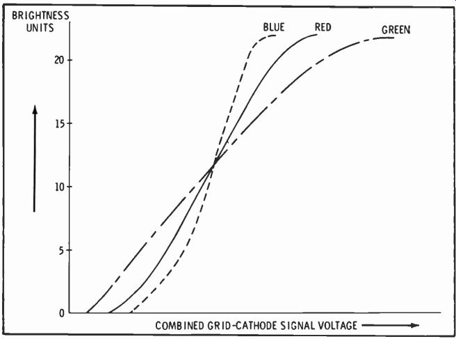
Fig. 1. Possible gain variations of the three CRT guns.
Fig. 1 is a graph showing the brightness produced by each of the three guns in a hypothetical CRT. These curves show no specific quantities but only a relationship between the three guns. In this hypothetical tube, if white were produced at 12 brightness units, the screen would tend to become blue with increased brightness. At brightness levels less than 12, it would be predominantly green. By decreasing the transconductance of the blue gun and increasing the transconductance of the green gun, reference white can be obtained at all brightness levels. This, of course, is known as gray-scale tracking.
CRT Geometry
At the present state of the art, the color tube most commonly used has three guns spaced at equal angles around the axis of the tube, a shadow mask with color-dot triads, electromagnetic deflection and convergence, and electrostatic focus.
Fig. 2 is a cross section of the neck of a CRT showing the position
of the three guns. Notice that the red and green guns share a common horizontal plane while each gun lies in its own vertical plane. A view of two gun assemblies is shown in Fig. 3. A close examination of these gun assemblies would show that each of the three guns is tilted so that the three beams will converge at a common point at the center of the shadow mask. This simplifies the convergence circuitry associated with the tube.
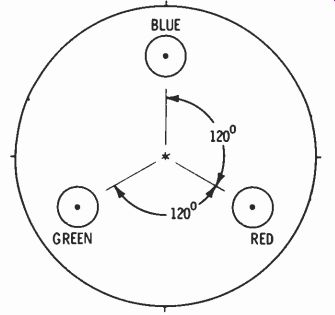
Fig. 2. Cross section of CRT neck.
As shown in Fig. 3, each gun consists of a heater, cathode, control grid (No. 1), accelerating grid (No. 2), focusing grid (No. 3), and a final accelerating grid (No. 4) which, since it is connected to the neck coating and shadow mask, is part of the ultor or high-voltage anode of the tube. A pair of pole pieces are located at the end opposite the cathode of each gun. These are used in conjunction with external fixed magnets and electromagnets to position the beams to provide proper convergence. In some CRT's, an additional set of pole pieces are situated adjacent to the focusing grid of the blue gun.
These, too, are used in conjunction with an external magnet (the blue lateral magnet) to aid in converging the blue beam with the other two.
Fig. 4 A shows a side view of a typical 23V color CRT with the deflection components in place, and Fig. 4B is a cutaway view of a 19V tube. Of particular interest is the arrangement of the shadow mask and phosphor screen. The shadow mask is a thin sheet of metal which has been perforated with a series of very small holes by a photoengraving process.
For each hole in the mask, three bits of colored phosphorescent material are deposited on the face plate of the tube in a pattern called a triad. These dots are arranged so that electrons emanating from the red gun pass through a specific hole in the mask and excite the red phosphor dot. At the same time, electrons from the blue gun pass through the same hole in the shadow mask to excite the blue phosphor dot; and, of course, the electron beam originating at the green gun at this same instant passes through the identical hole and excites the green phosphor dot.
A. 23V rectangular tube. B. 19V round tube.
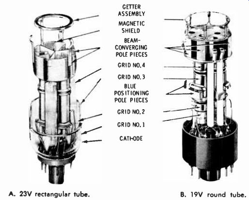
Fig. 3. Typical electron-gun assemblies.
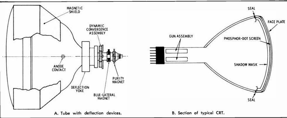
Fig. 4. Details of CRT construction. A. Tube with deflection devices. B. Section
of typical CRT.
Color Purity
The degree of color purity depends on how well the beams from the guns actually pass through the holes in the shadow mask to strike the phosphor dots. The two variables which affect purity are the distance from the deflection plane to the shadow mask and the points on this plane through which the beams pass. Fig. 5 illustrates these two variables.
The relative positions of the phosphor dots and the holes in the mask were fixed at the time of manufacture of the CRT. These positions are such that if lines were to be drawn from each red dot, through their respective holes in the mask, toward the neck of the tube, all of the lines would come together at one precise point. In making the purity adjustments, the beam from the red gun is made to emanate from this same point, which is somewhere on the correct deflection plane.
Referring to Fig. 5, notice that the correct point and two incorrect points of apparent beam origin are shown. If the beam emanates from an incorrect point on the proper deflection plane (point A), it will miss the red phosphor dots at the edges of the screen and also at the center. On the other hand, even though the deflection plane is incorrect, if the point of origin is correct (point B), the beam will hit the red dots near the center of the screen but miss them at the edges.
The correct procedure for adjusting purity may be inferred from this discussion. If the deflection. yoke is moved toward the rear of the CRT as far as possible, it will be in the vicinity of the incorrect deflection plane shown in Fig. 5. This allows the purity magnet to be adjusted for the proper point of apparent beam origin (point B of Fig. 5), as evidenced by a pure red area at the center of the raster.
Then the yoke is moved forward until red purity is obtained over the entire raster.
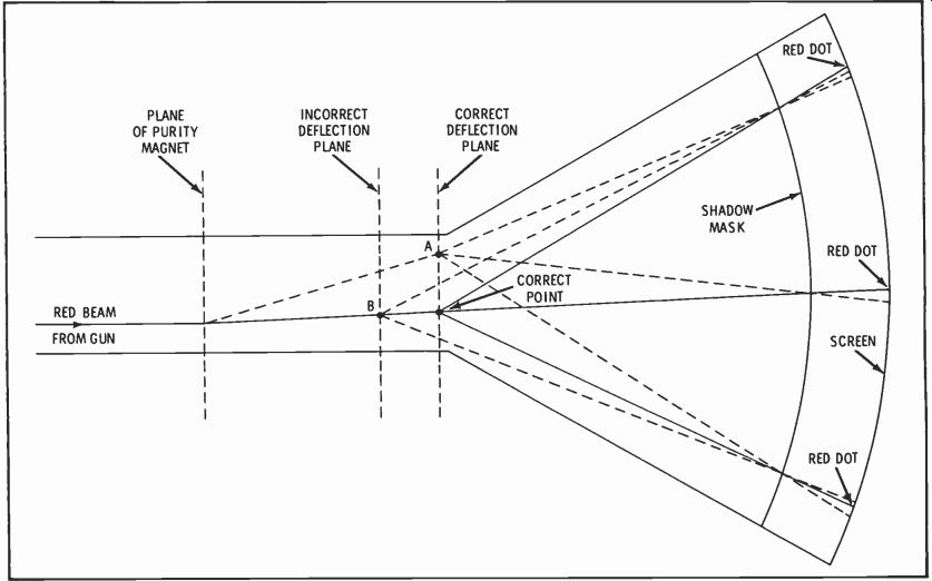
Fig. 5. Deflection geometry showing effects of purity adjustments.
The purity magnet must be capable of producing a uniform magnetic field of adjustable intensity perpendicular to the neck of the CRT. Also, this field must be capable of being oriented in any direction. To accomplish this, two magnetic rings, each polarized as shown in Fig. 6, are mounted on the CRT neck. Depending on the relative position of the two rings, their fields will either aid or oppose each other to determine the intensity of the field. To determine the direction of the field, the two rings are rotated together.
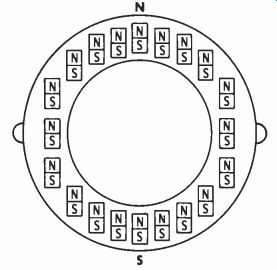
Fig. 6. A typical purity magnet.
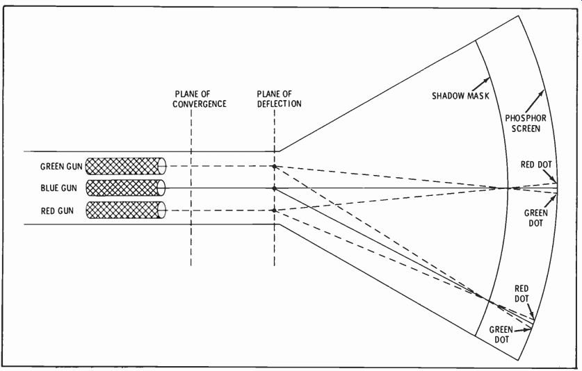
Fig. 7. Deflection geometry showing correct convergence.
In discussing purity, we have considered only the red beam and phosphor dots and, in fact, the blue and green guns are normally disabled while making purity adjustments.
This procedure is acceptable since the blue and green beams are deflected the same amount by the purity magnet as was the red beam and, consequently, are automatically positioned at approximately the correct points on the deflection plane.
The subsequent convergence adjustments position the points precisely to their correct locations.
Static Convergence
Fig. 7 is a distorted view of a color CRT which illustrates some of the geometrical aspects of convergence. The distance from the shadow mask to the phosphor screen has been increased while the distance from the tube neck to the shadow mask has been decreased so that the divergence of the beams after they pass through the mask may be seen. The plane depicted in Fig. 7 is horizontal, that is, the observer is looking down at the CRT and the center horizontal line of the CRT is being scanned by the electron beams. In actual practice, the plane of the convergence yoke is to the rear of the plane of the deflection yoke; however, for the purposes of this discussion the two planes are assumed to coincide. This greatly simplifies the explanation and, from a qualitative point of view, has no effect on the operation of the convergence system.
Consider the moment when the triad at the center of the screen is illuminated. The beam from the green gun crosses from left to right (looking from the guns toward the screen), the red beam crosses from right to left and the blue beam goes straight ahead. (Actually the red and green beams are aimed upwards slightly and the blue beam is slightly depressed, but this cannot be observed from the present point of observation). When the three beams actually behave as shown, the tube is correctly converged at the center.
This is called static convergence, since there is no horizontal or vertical-deflection field acting on the beams at this instant.
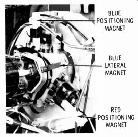
Fig. 8. Convergence components.
From the above, it may be inferred that static convergence consists simply of aiming all three guns at the center of the CRT screen.
This is accomplished by adjusting the three permanent magnets which are part of the convergence yoke so that the electron beams are correctly aimed. Fig. 8 shows the red and blue positioning magnets and the blue lateral magnet, soon to be discussed. The positioning magnets themselves are imbedded in a plastic sleeve, and these sleeves may be pushed in closer to the CRT neck to increase the effect of the fields.
The sleeves may be rotated 180° in their holders to reverse the magnetic field if necessary. Of course, other magnet configurations are possible, but the operation is essentially the same.
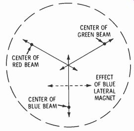
Fig. 9. CRT screen section shows effects of static-convergence magnets
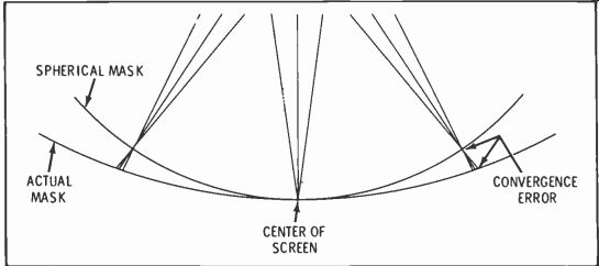
Fig. 10. Dynamic-convergence error due to non-spherical mask.
Fig. 9 shows the effect of the positioning magnets on their respective beams. As the red and green positioning magnets are repositioned, the respective beams scan the screen in the direction shown by the arrows. Since the guns are aimed, roughly, at the center of the CRT during manufacture, the landing points of the red and green beams can be made to coincide at some point near the center of the screen. The blue positioning magnet causes the blue beam to fall at some point along a vertical line on the screen (also near the center), which point is determined at will by adjusting the positioning magnet.
When the blue spot is directly alongside the spot illuminated by the red and green beams, the blue lateral magnet (also pointed out in Fig. 8) is adjusted to move the blue spot horizontally until all three spots coincide.
The blue lateral magnet is mounted on the CRT neck to the rear of the convergence yoke and is situated at right angles to the blue positioning magnet. Because of its position, the only one available, it has a slight effect on the red and green beams as well as on the blue beam. Accordingly, the position of all four magnets must be "roughed in" first and then retouched for best convergence.
Dynamic Convergence
Unlike static convergence, which may be accomplished by permanent magnets, dynamic convergence requires the generation of fairly complex magnetic fields. Before examining the circuitry required to produce these fields, let's define dynamic convergence and describe the magnetic fields which are required to accomplish it.
The major factor which affects dynamic convergence is the curvature (or rather, the lack of it) of the shadow mask and screen. If the screen were a sector of a sphere whose center was on the convergence plane, dynamic convergence would be relatively simple. However, the screen has a radius much greater than the distance to the deflection plane and , if nothing is done to correct it, a beam which is converged at the center of the screen will converge behind the mask at every other deflection angle. This is illustrated in Fig. 10. Accordingly, progressively less convergence field is required as the deflection field increases. Notice, too, that dynamic convergence is required for the vertical sweep as well as the horizontal sweep.
Fig. 11 shows the effect of no dynamic convergence on vertical and horizontal lines passing through the center of the raster. In considering the effects of convergence, these lines are of particular interest because the dynamic horizontal-convergence field is zero when these vertical lines are being produced, and the dynamic vertical-convergence field is zero when the center horizontal lines are being produced.
The total dynamic-convergence field when any other point on the raster is being scanned is a sum of both the horizontal- and vertical-convergence fields.
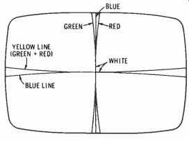
Fig. 11. Raster with dynamic convergence circuits disabled.
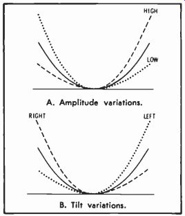
Fig. 12. Parabolic-current waveforms.
Notice that three vertical, but only two horizontal, lines are produced. This is easily understood if one considers that each gun is in a separate vertical plane, but that the red and green guns are in the same horizontal plane. Thus the red and green beams track each other in a horizontal scanning line.
The curves produced on the raster by un-converged beams are parabolic in shape, and so a parabolic correction current through the convergence coils will straighten the lines. Although it is possible to dynamically converge all three beams with a single device, it is standard practice to use independent electromagnets for each gun and to generate separate currents for each of them. By doing this, the amplitude and the tilt (angle of the axis of the parabola relative to the vertical axis of a graph) of the current in each convergence coil may be adjusted for the best possible appearance of the raster. Fig. 12 relates the terms "tilt" and "amplitude" to a parabola.
Referring to Fig. 8, the red and blue dynamic-convergence electromagnets may be seen immediately in front of the red and blue positioning magnets. Fig. 13 shows a single convergence electromagnet and illustrates the relative size of the horizontal- and vertical-convergence coils. Since the horizontal- and vertical-convergence currents have the same repetition rate as the horizontal- and vertical-deflection oscillators, the vertical-convergence coils must have many more turns to obtain a reasonable impedance.
The circuitry used to develop the convergence currents will be discussed later in this article.
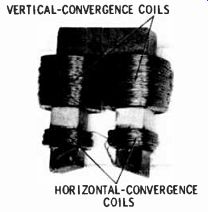
Fig. 13. Typical dynamic-convergence electromagnet.
Pincushion Effect
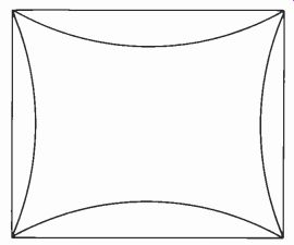
Fig. 14. Pincushion distortion.
Those who were in the TV servicing business a generation ago will recall when the effects of pincushion distortion first became a problem.
In the earliest black-and-white sets, using a small deflection angle and a near-spherical screen with a fairly short radius, pincushion distortion was no problem. Then, as wider deflection angles and flatter screens became popular, pincushioning became objectionable. Fig. 14 shows a raster with severe pincushioning.
Actually, pincushion distortion is aggravated by the use of cosine or cosine-squared yokes, necessary to maintain focus over the surface of the flat-screen, wide-deflection CRT. In b-w sets, pincushion correction is fairly simple. By positioning small permanent magnets around the CRT, just forward from the deflection yoke, the beam is caused to move outward as it crosses the horizontal and vertical center lines, straightening the scan lines on the CRT. Unfortunately, the use of pincushion magnets in a color set is not possible. As we all know, it is problem enough to get rid of magnetic fields around the CRT bulb without introducing any additional magnets. Secondly, since the three beams have different points of origin on the deflection plane, pincushion magnets would not affect the three beams equally, making convergence at the edges of the CRT very difficult.
Since the use of pincushion magnets is precluded, the correction field must be generated electromagnetically. Small correcting currents are generated in the pincushion circuit and added to the deflection currents in the yoke. A typical circuit will be examined under a separate head in this article.
Dynamic-Convergence Circuits
As pointed out previously, the currents through the dynamic-convergence electromagnets must be parabolic in shape and have controllable amplitude and tilt. This is true of both the horizontal and vertical dynamic-convergence currents; however, since the circuits used to generate these currents are different, they will be discussed separately.
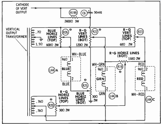
Fig. 15. Typical vertical-dynamic-convergence circuit.
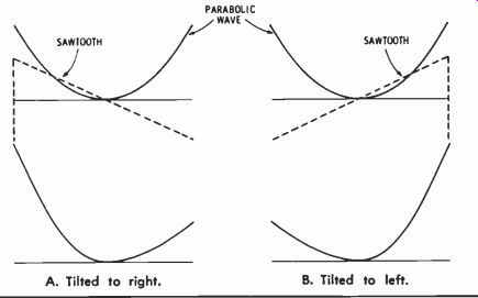
Fig. 16. Result of adding parabolic and sawtooth currents.
Fig. 15 shows the vertical dynamic-convergence circuit used in the Admiral 2Gl 156-1 chassis. The sawtooth from the cathode of the vertical-output tube is fed through C6 and R199 to the top of a bleeder, consisting of R22 and R25, and thence to ground. A portion of this voltage is picked off by the slider of R25 which connects to one end of the blue convergence coil, L44A. The opposite end of L44A is connected to the slider of R26 which, in turn, is across a winding of the vertical output transformer. Thus, the parabolic current waveform produced by the action of R199, C6, and L44A is modified by the saw tooth current from the transformer winding. This is illustrated in Fig.
16. Since the ends of the transformer are out of phase, either a positive-going or negative-going current may be picked off by the slider of R26; and the parabola may be tilted in either direction.
In considering the currents through L44B and C, we will first trace the current produced by the lower winding of the vertical-output transformer of Fig. 15. The amplitude and phase of voltage taken from this winding is determined by the setting of R20. The relative amplitudes of this voltage which are fed to L44B and C is determined by the position of the slider of R19.
Notice that as more current is caused to pass through one coil, less passes through the other; but that if current flow through one coil is from terminal 1 to terminal 2, it is from 2 to 1 in the other.
A second sawtooth is taken from the upper winding of the vertical output transformer. This is tapped by R23 and fed through L44C, then L44B, to the slider of R22, and ultimately back to ground. Since the setting of R23 determines the phase of this sawtooth, current may be in either direction, but if it passes from 2 to 1 of L44C, it also passes from 2 to 1 of L44B. In either case this sawtooth modifies the tilt of the parabolic current supplied from R22. Depending on the positions of the various controls, R23, R19, R20, and R22, the amplitude and tilt of the parabolic currents through the red and green coils may be adjusted over a wide range.
Fig. 17 shows a typical horizontal-convergence circuit. Although the current waveforms are very similar to the ones developed in the vertical-convergence circuits (except for frequency), the circuitry is somewhat different. These circuit differences are present because a suitable sawtooth input is not available and also because the red and green guns are in the same horizontal plane and require approximately the same convergence current.
The input for red and green convergence is a 300-volt pulse from the horizontal-output transformer.
This is shaped into a sawtooth by L1 and a parabolic current is caused to flow through the coils.
The ganged potentiometers, R8A and B, arc connected so that the current returns to ground through either of two windings. These windings arc out of phase, and so the parabolic current may be tilted in either direction, depending on the setting of the potentiometers. Notice that the potentiometers are connected so that the currents in the two coils tilt in opposite directions.
R9 changes the loading on the saw tooth at the top of C8 and has the effect of tilting the parabolic current in each of the two coils in the same direction.
Blue horizontal convergence is accomplished by a parabolic current developed by the network consisting of L2, L3, C6, and C7. A portion of the 30-volt pulse fed to R I0 is fed to the network. L3 and C7 are tuned to 15,750 Hz while L2 and C6 are tuned to the second harmonic, 31.5 kHz. The combination of these impedances causes a parabolic current in the convergence coil. By tuning L2 above or below its center frequency, the current may be tilted in either direction at will.
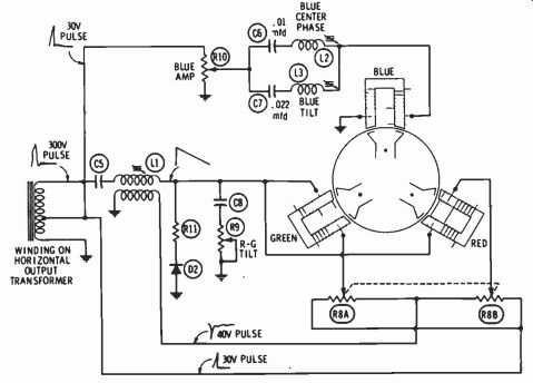
Fig. 17. Typical horizontal-dynamic-convergence circuit.
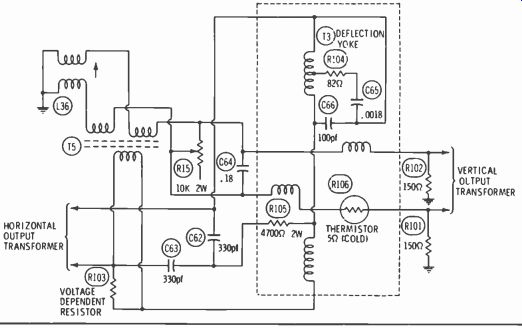
Fig. 18. Typical pincushion-correction circuit.
Pincushion Circuit
To correct pincushion distortion at the top and bottom of the screen, it is necessary to decrease the vertical-deflection current in the yoke when the horizontal scan is at the extreme right and left edges of the screen. Correcting pincushion distortion at the sides of the screen is accomplished by decreasing the amplitude of the horizontal deflection current when the vertical deflection is at its maximum upper and lower limits. The circuit in Fig. 18 shows one way of accomplishing this.
In Fig. 18, a portion of the horizontal deflection current flows through the bottom winding of T5, inducing a current in the two secondaries. The phase of this induced current is adjusted by the slug in L36 so that it opposes the vertical sweep current at the time when the horizontal scan is at the edges of the screen. Thus, the vertical deflection is reduced only at the edges of the raster. The amount of reduction of the vertical sweep is determined by the setting of R15.
Side pincushioning is also corrected by the same circuit. A portion of the vertical-deflection current passing through the two upper windings of T5 induces a voltage in the lower winding which opposes the horizontal deflection current. This opposing voltage must be present only when the top and bottom of the CRT are being scanned. This is accomplished by using a saturable core in T5. The core saturates when the vertical sweep is near the center of the raster and, consequently, there is only a small transfer of energy in the transformer. As the core comes out of saturation, more and more vertical-sweep energy is coupled to the horizontal deflection system so that the scan lines are shortened at the top and bottom of the picture.
The Sony One-Gun Color Picture Tube
The Sony one-gun Trinitron color picture tube often is confused with a different color CRT called the chromatron, which never got into a commercial set. But they're definitely not the same. Nor even much alike. To end any mix-up, here's a thorough description of the Trinitron, how it works and what its advantages are.
For the most part, this little portable looks and operates much like any other color set.
That is, it does until you open it up and look for the adjustments.
--- Trinitron-- A Sony Trademark.
Then it's a different story. There are so few-only a half-dozen, including convergence. That's a far cry from the couple dozen a conventional picture tube needs.
Color by Vertical Stripes
The first odd thing you notice about a Trinitron picture tube is its color phosphors. There are three primary colors-red, green, blue--just as in a regular color CRT. But these in the Trinitron are deposited on the tube face in vertical stripes, side by side. There's a red, then a green, then a blue: then another red, another green, another blue, and so on, as shown in Fig. 19.
The second unusual thing is the Trinitron shadow mask. It doesn't have holes like a conventional one.
It has slots. It's not even called a shadow mask; it's called an aperture grille.
You can see its relationship to the phosphor stripes in Fig. 19. It's just behind the stripes, between them and the guns. The vertical slots line up with the green phosphor. Each slot is only as wide as one stripe. You can see from the sketch, the slots and stripes are both much narrower than the beam of electrons from the electron gun.
One Gun, Three Beams
To understand how the aperture grille works, you need to know what the electron gun of the Trinitron does.
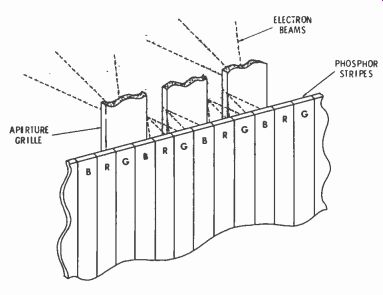
Fig. 19 Phosphors are deposited on screen in vertical stripes. Aperture grille
is really a vertically slotted shadow mask.
Conventional color CRT's have three guns. The Trinitron has only one. But it puts out three beams.
How that's done is illustrated in Fig. 20. First, look at Fig. 22 and how the aperture grille masks each of three beams. It allows each beam to hit only the phosphor it's supposed to excite.
Each beam covers at least two of the slots in the grille. The green beam, coming straight in, hits green phosphor stripes. The red beam comes into the slots at an angle set by the convergence plates. It strikes two red stripes, but can't hit blue or green-the grille prevents it. Likewise, the blue beam, coming through the grille slots from the opposite angle, can't hit red or green stripes--only blue.
Getting purity in the center is easy. But when the yoke sweeps the beams, they could easily land wrong.
The yoke has to be in just the right position along the CRT neck so the point of deflection (called deflection center) is correct. Fig. 21 illustrates this.
There arc three cathodes. Each one emits a bunch of electrons that are gathered roughly into a beam when they go through a hole in the control grid, or G1. The three cathodes are in line horizontally side by side and so are the three holes in G1. Green is in the middle.
Another grid, G2, is an accelerating anode. It's also called the screen grid. It speeds up the electrons in the three beams as they pass through the three holes in the 02 structure.
The beams, now with plenty of energy, enter the first of a set of focus elements. A DC field bends the blue and red beams toward the middle. At one spot inside this focus assembly, they cross over each other and the green beam. In the same process, each stream of electrons is concentrated into a tight, round beam. Green continues straight ahead. The red and blue beams angle off, aimed toward opposite edges of the screen.
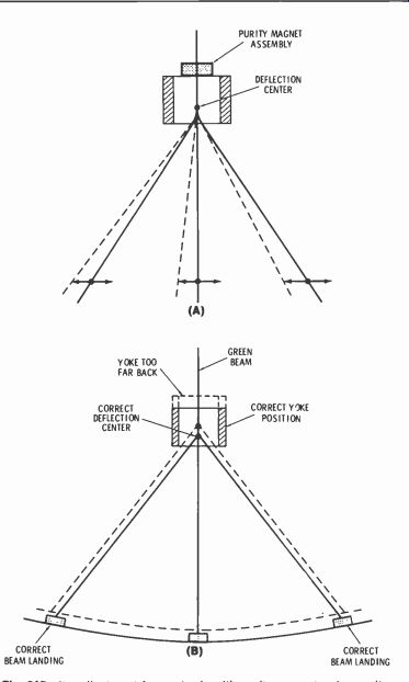
Fig. 21. Purity adjustment for center is with purity magnet; edge purity is
adjusted by sliding yoke. Best to check green and red for purity.
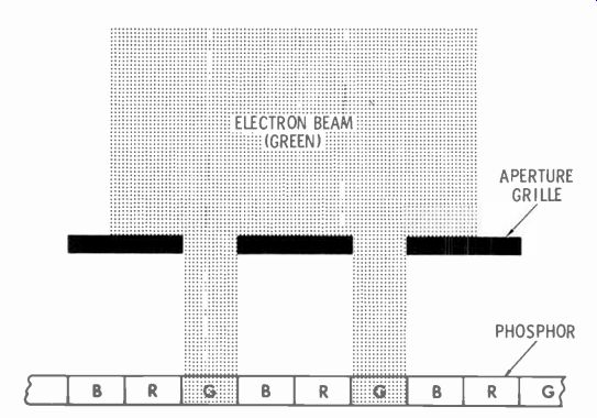
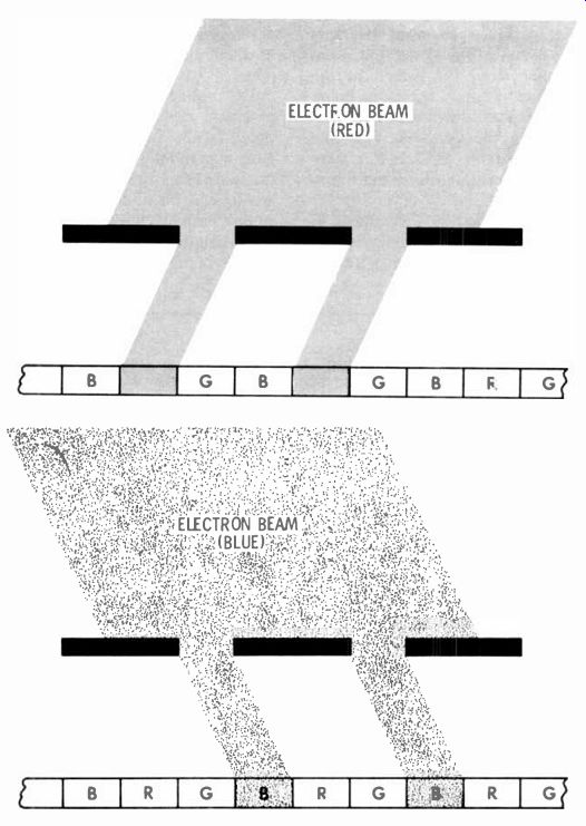

Fig. 22 Masking effect of aperture-grille slots. Angles of beams are adjusted
so they illuminate only the phosphor for their own color.
Before they've gone very far, all three beams pass through an array of convergence plates. Those plates carry the same 19 KV supplied to the second anode. The static field and the shape of the plates bend the red and blue beams back to ward each other and the green beam. lithe voltage is exactly right, all three beams meet again (converge) right at the aperture grille.
One Color Per Beam
The aperture grille and its relationship to the deflection yoke are the key to color purity and easy convergence in the Trinitron.
A purity magnet (Fig. 21A) mainly affects how the beams land near the center of the screen. The arrows show how shifting the magnet moves beam relationships. If you're adjusting the purity magnet, you try for best purity in the center. Use a green raster.
Fig. 21B illustrates yoke positioning. If it's too far back on the neck, the deflection center is out of position. Out near the edges, the beams don't go through the slots like they're supposed to. You adjust for best purity all over the screen by sliding the yoke forward or backward on the neck of the CRT. There's one more adjustment to assure that each beam lands on only its intended color. It's called the Neck-Twist Coil. Slight misalignment in the gun may keep the three beams from lining up horizontally.
The effect is shown above the photo of the coil, in Fig. 23. The red or blue beam may spill over onto some green stripes. Turning the neck-twist coil corrects this. During adjustment, watch a red raster; this adjustment doesn't affect green.
Converging at the Edges With purity as good as you can get it, turn your attention to keeping the beams going through the slots together all the way across the screen. The face of the Trinitron is only slightly convex. The angle of beam deflection inscribes a much shorter radius.
Fig. 24 illustrates what this does to the beams. The deflection point is further from the screen at the edges than at the center. If the beam crossover point stays the same distance from the gun, out near the edges the beams cross before they reach the aperture grille. That's mis convergence.
What's needed is something to lengthen their focal distance at the beginning of each line, let it return to normal as the beams sweep across center, and lengthen it again as they move on toward the right edge.
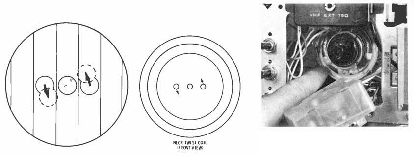
Fig. 23 Neck-twist coil is rotated to improve green purity. DC flowing in
it keeps the three CRT beams lined up horizontally.
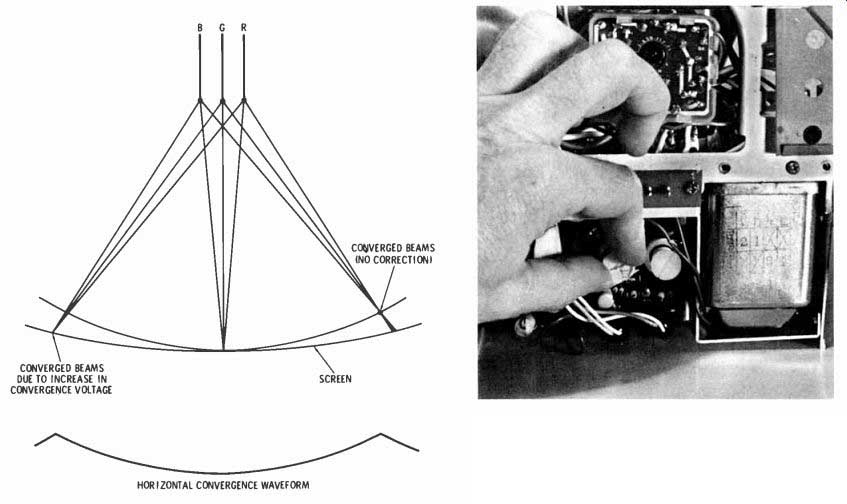
Fig. 24 Sketch shows how parabolic waveform added convergence plates lengthens
focal point of beams as they sweep toward edges. The controls in the photo
are the only convergence adjustments you normally will make.
DC voltage on the convergence assembly determines the crossover point in the first place. So, logically, a parabolic voltage that's perfectly in step with the horizontal sweep can be added to it; the resulting voltage variation alters the focal length as needed.
The parabolic voltage waveform is shown in Fig. 24, below the sweep sketch. Applied to the convergence plates, the parabolic voltage adds to the 19- KV DC that's already there.
Rising and falling, it stiffens the beams during the start and finish of each line-moving the focal point out and back to conform exactly with aperture-grille curvature.
That's all there is to horizontal convergence. The circuit is simple.
A parabolic signal is taken from the horizontal-yoke return circuit and fed through a capacitor to the convergence plates.
Vertical convergence is even simpler. Slight vertical misconvergence doesn't show up anyway; if a beam lands a little high, it's still on the same color stripe so there's no visible error. Whatever slight correction is needed is designed into the vertical output stage and deflection coils.
There are only two convergence adjustments (Fig. 24). One is the Vertical Static adjustment. You make it first. Just put horizontal crosshatch lines on the screen and adjust the control to converge them.
The other, the Horizontal Dynamic adjustment, primarily affects vertical crosshatch lines. It makes one end or the other of the parabolic signal higher in value, in case a little extra beam-stiffening is needed toward one side of the screen.
There's also a capacitor you can change to improve convergence if a replacement Trinitron cannot be set up correctly.
Powering the Trinitron Supply circuits for the Trinitron are diagramed in Fig. 25. The photo shows the second-anode button and the 19-KV high-voltage connection.
As mentioned earlier, there are three cathodes. They are the driven elements in the Trinitron. Color video signals; to which the Y or brightness components have already been restored, are fed to the cathodes. They control how many electrons get into the beams, and thus determine average scene brightness and the mixture of primary colors that make a color scene. About 70 peak-to-peak volts of video are applied to them.
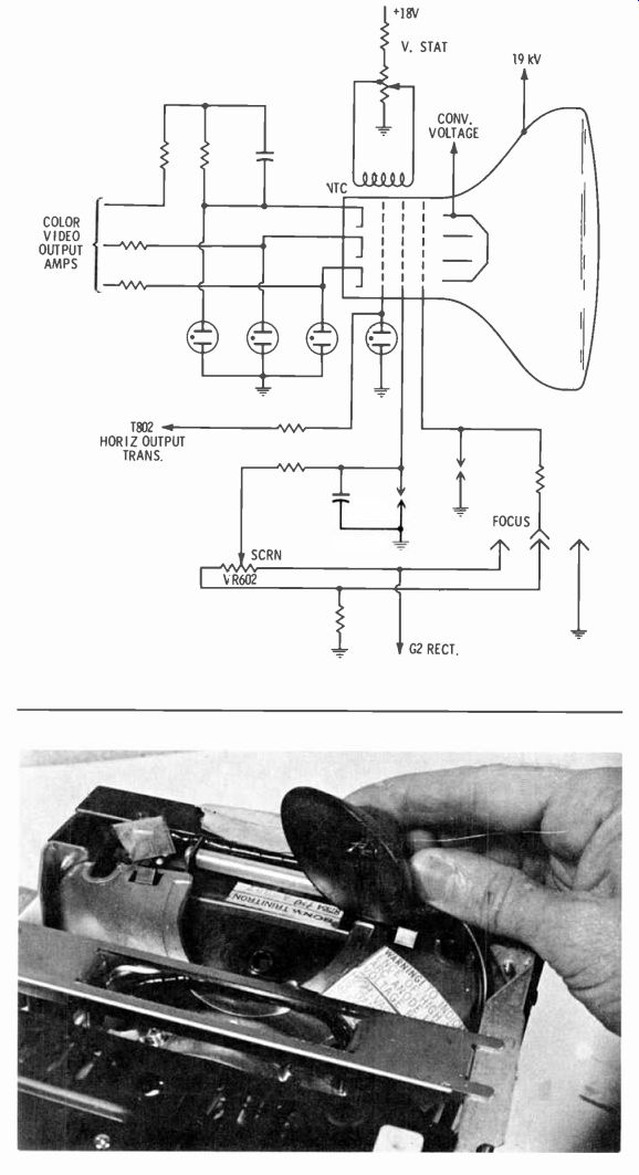
Fig. 25 Circuitry surrounding Trinitron picture tube stresses simplicity,
compared with shadow-mask-tube circuits. Photo shows second-anode cap at top
of tube instead of at side of bell as in conventional CRT's.
The control grid (G1) is common to all three beams. With the cathodes driven, GI stays at ground (zero volts) potential most of the time. Average bias is set by whatever average DC is on the cathodes--about 100 volts DC. However, horizontal and vertical blanking pulses are fed to the grid, driving it deeply negative for those short intervals when they are present.
The efficiency of Trinitron phosphors is closely matched for all colors. Also, because of the common G I transconductance for each beam is about the same. There's no need for complex gain adjustments, so the screen (G2) is common to all beams, too. No gray-scale tracking is necessary. There's no series of screen adjustments-just one It varies the DC voltage applied to G2--between 300 and 400 volts.
Focus voltage can be varied from zero (ground) potential to the full voltage that's available for G2. I have already indicated the voltage on the convergence plates; it's 19 KV, plus the parabolic dynamic convergence signal.
A Step Toward Easier Servicing
The Trinitron is simpler than picture tubes of the three-gun shadow mask variety. There's less to go bad inside and outside a Trinitron.
The Trinitron color portables I've seen in operation produce a satisfactory picture. Convergence was good, and colors seemed warm and true. Color pictures are bright enough to be viewed comfortably under strong fluorescent lighting, but they don't seem any brighter than (if as bright as) pictures on the new black-surround color CRT's it some U.S. brands.
Whatever its other advantages, the Trinitron is unique and easy to set up.
Conclusion
The preceding Section was written to explain how the geometry of the color CRT places certain requirements on the circuitry associated with it. After these requirements were pointed out, typical circuits which perform the various functions were described. Since specific circuits vary widely from one make of set to another, generalized setup procedures are almost pointless and no attempt has been made to formulate them. Through careful attention to the appropriate service data, and experience in making the various adjustments, you will evolve the techniques best suited to your specific requirements.