The only motor in RCA's remotely controlled CTC47 color TV chassis is the UHF tuning motor; remote control of VHF channel selection, the on/off function and adjustment of volume, tint and color saturation is accomplished electronically without motors.
How the volume, tint and color saturation remote control circuits operate will be explained in this article, along with techniques for tracking down troubles in them.
How Functions Are Controlled
One of the basic differences between motor-controlled and motor less-controlled is the way in which volume, tint and color are made to vary. Because it is the most simple, let's start with volume control: Fig. 1 illustrates the conventional method of controlling volume. The circuit itself is so simple that it requires no explanation; the point is that something has to turn the shaft of the potentiometer.
Now let's explore some alternate methods of controlling volume. If we were dealing with vacuum-tube circuits, we might use an audio-amplifier tube with remote-cutoff characteristics, and control its gain by varying the bias. This is similar to controlling the gain of an IF amplifier by varying the AGC bias applied to it. However, a couple of problems arise: First, remote-cutoff tubes tend to produce distortion when they are used with fairly high-level signals, such as those from the sound FM detector of a TV receiver; and second, tubes are no longer used in most television audio sections.
Controlling the volume by varying the bias of an audio-amplifier transistor also can lead to distortion problems, just as in vacuum-tube amplifiers.
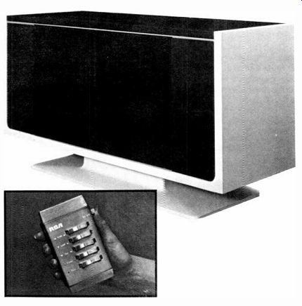
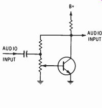
Fig. 1 Conventional volume control and audio amplifier
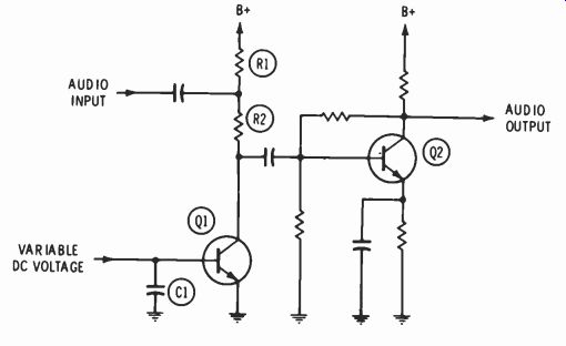
Fig. 2 Audio amplifier with DC volume control.
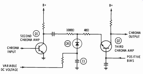
Fig. 3 Gain-controlled chroma amplifier using DC control voltage.
There is, however, another approach: The use of a transistor as a signal-shunting device. The fundamental circuit is shown in Fig. 2.
If the base-bias voltage of Q1 is zero, Q1 appears as an open circuit from collector to ground, there is no attenuation of the signal passing to Q2, and the output volume is maximum. However, as Q1 is biased into conduction, the impedance from collector to ground decreases, reaching nearly zero when Q1 is saturated. As the collector impedance of Q1 decreases, more and more signal is dropped across R2, and the volume is progressively reduced. If the supply voltage for Q1 is large in comparison to the signal, the instantaneous changes in collector voltage, caused by the signal, will not have much effect on the impedance to ground, and significant distortion will not be produced.
This volume-control configuration actually has two advantages: One of these applies regardless of whether or not wireless remote control is anticipated. Because the audio signal itself does not need to be carried via wiring to the controlled stage, pick-up of hum and other spurious signals, which often occurs when a volume control is physically separated from the amplifiers, does not occur. Any stray AC voltages which might induce a spurious signal on the conductor leading to the base of Q1 will be shunted by C1, whose capacitance can be as large as necessary.
The second advantage is related to the first. Because the proposed remote-control system now needs to generate only a DC voltage, there is no need for a mechanical device.
Obviously, the circuit in Fig. 2 could be adapted to control color level instead of volume, since the functions are essentially the same.
In the RCA CTC47, the volume control circuit is similar to Fig. 2, hut the active devices are contained in an integrated circuit (IC). A simplified version of the color control circuit appears in Fig. 3.
Diode CR1 is the signal-shunt device in this circuit. As the variable bias is made more positive, the impedance of CR1 decreases, again shunting more signal to ground and allowing less to pass to the 3rd chroma amplifier. As with the volume control circuit, there is no signal on the control line and spurious signals which might be picked up arc grounded by C1.
Remote control of tint is a bit more complicated because the phase of a signal must be controlled, rather than its amplitude. A convenient way of doing this is to split the reference signal into two signals having different phases, separately control their relative amplitudes, and then recombine them.
In Fig. 4, reference signals from the 3.58-MHz oscillator drive the bases of Q1 and Q2 in phase; however, the RL emitter impedance of Q1 and the RC emitter impedance of Q2 cause the phases of the collector signals to be about 90 degrees from the input phase, respectively. Assuming the transistors are biased equally, each will supply half of the signal energy to the output transformer, and the combination of these two signals will produce an output in phase with the inputs to Q1 and Q2. (If the transformer secondary leads were reversed, the output signal would be 180 degrees out of phase with the input to Q1 and Q2.) Now, suppose the variable bias is made more positive. Q2 will amplify more than before, and the phase of the output signal approaches the phase present at the emitter of Q2. At the same time, the increased current through Q2 increases the voltage drop across R1, biasing Q1 toward cutoff. If the variable bias is made less positive, the gain of Q2 will decrease, the gain of Q1 will increase, and the phase of the output will shift in the opposite direction.
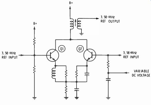
Fig. 4 DC-controlled tint circuit.
Memory Circuits
In a motor-driven remote-control system, the problem of memory does not arise, because once the motor comes to rest at the desired position, it will remain there. In a motorless system, the problem of memory becomes serious.
The circuit in Fig. 5, which has no memory capability, illustrates the point. Suppose the relay is closed by means of a hand transmitter and remote receiver. If R1 and C1 are very large, the voltage fed to the volume (or tint, or color) circuit will increase quite slowly, causing the volume to increase also. When the volume reaches a pleasant level, the operator releases the button and settles back to enjoy the program; however, C1 will gradually discharge through Q1 (of Fig. 2), and the volume again will increase back to maximum.
If discharge of C1 can be prevented, the volume will remain constant, once set, and memory will have been achieved. In Fig. 6, the basic configuration of a memory circuit is illustrated. In this circuit, the capacitance between gate and channel of the MOSFET, Q1, will charge towards B+ any time the contacts of K1 are closed. However, since the input capacitance of Q1 is about 5 pf, a charging resistance of several thousand megohms would be necessary to make the charging time long enough for a person to control it. To increase the charging time, C1 (about 1 mfd) is connected to ground.
Once the relay contacts are opened, there is no discharge path for C1 or the input capacitance of Q1, except through the leakage resistance of CI and the MOSFET gate; this resistance can be made as high as several thousand megohms, and the time constant thus produced is in excess of several days, perhaps months. As we shall see later, this time can be extended even further. Q1 and Q2 serve as drain- and emitter-followers, respectively, to develop sufficient current handling capacitance for the controlled circuit.
In addition to remote control, normally it is desirable to allow control of volume, tint and color at the receiver itself. One method of modifying the circuit of Fig. 6 to allow local control is to simply connect pushbutton switches across the "up" .and "down" relay contacts.
The use of remote controls which require that the button be depressed long enough for the function to change are acceptable, but people generally object to similar "time-consuming" controls located on the receiver itself. For some reason, a potentiometer type of control on the receiver is more pleasing. Also, as we shall see in the circuits described below, use of the potentiometer in the receiver improves the memory function.
In Fig. 7, C1 is returned to the wiper of a local-control potentiometer instead of ground; otherwise the circuit is the same as Fig. 6.
However, in Fig. 7 the voltage on the gate of the MOSFET will be almost exactly the same as the voltage at the potentiometer wiper. This can be understood better if we consider C1 and the input capacitance as a voltage divider connected from the potentiometer to ground. Because the voltages across series capacitors arc inversely proportional to their capacitances, and the value of C1 is about 200,000 times the input capacitance of Q1, essentially all the applied voltage is present on the MOSFET gate.
Assume that R1 in Fig. 7 has been set to produce normal volume, and +3 volts exists on the MOSFET gate. By actuating the remote "volume down" switch, the appropriate relay contact is closed and both C1 and the MOSFET input capacitance are charged to some higher voltage-in this example, 4 volts. Since the voltage across C1 is only 1 volt, instead of 4 volts as it would be in Fig. 6, the leakage current is one fourth as great, and memory is increased by a factor of four. (Since the gate resistance is almost infinite, the leakage current through it can be ignored.) Furthermore, even if C1 leaks significantly, the volume will return to the original level determined by 121 instead of to maximum, to which it would return in Fig. 6.
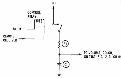
Fig. 5 Remote-control voltage source.
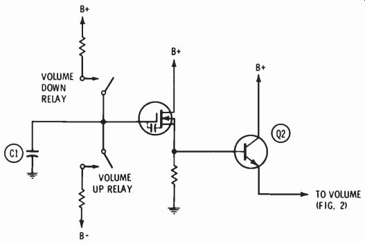
Fig. 6 Basic memory circuit and volume-control driver.
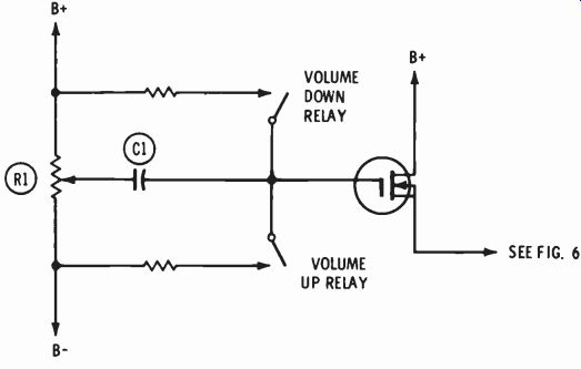
Fig. 7 Memory control circuit with local and remote inputs.
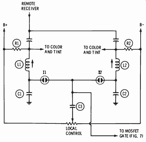
Fig. 8 Memory circuit input using electronic switches.
Electronic Switching
So far we have assumed relays were used to connect the voltage to the MOSFET. In the actual design, the relays have been replaced by electronic switches, as illustrated in Fig. 8.
When the "volume down" remote button on the transmitter is depressed, the transmitted frequency picked up by the remote receiver is the same as the resonant frequency of L1 and C1. At this frequency, the impedance of L1 and C1 is near zero and the current is large. The voltage across C1 is high, perhaps 200 volts, because it is equal to I (current) times Xc (capacitive reactance), and this ignites the neon lamp, L1. Once ignited, the resistance of I1 is low, and DC voltage from the B+ supply charges the MOSFET gate through R1, as already described.
One final circuit refinement is required, although it is not immediately apparent. If no means were provided to discharge C3 back to zero volts, enough voltage eventually would accumulate on C3, by virtue of the remote control, to make local control impossible. For example, suppose the local control originally had been set for a comfortable volume, and remote control subsequently was used to increase the volume. Then suppose local control were used to reduce volume, and remote control were used to raise it once more. After this had been repeated a number of times, the local-control potentiometer would be at its limit and volume still would be high.
To prevent this, the local-control potentiometer is constructed with a "delta switch", which closes momentarily each time the shaft is turned, even a few degrees. The delta switch energizes a relay whose contacts are connected across C3.
Thus, each time the local control is used, all voltage resulting from remote control is cancelled, or discharged to the potentiometer wiper.
With the addition of the delta switch, either remote or local control can be used repeatedly in any sequence without a "hang-up" resulting.