General Trends:
Innovations in solid-state circuitry highlight the 1970 TV designs, while very few changes are evident in tube-powered chassis. Hybrid receivers .are numerous, with all the circuits transistorized except for vertical sweep, horizontal sweep, high voltage, video output and chroma-Y amplifiers.
Color TV continues to be the center of attention, with more color portables and more solid-state circuits. Field-effect transistors, spark gaps inside the CRT sockets, more plug-in boards or modules, and the beginnings of a trend to pre-CRT matrixing of chroma and video signals are just a few items of interest.
Emphasized in the manufacturers' service data are such safety precautions as high-voltage adjustments and the measurement of line-voltage leakage from exposed receiver parts to earth ground. High-voltage shunt regulators of the 6BK4 type are not used in many of the new receiver designs, as the manufacturers remain concerned about possible radiation hazards and more stringent government standards in the future.
Here are some of the most interesting 1970 features and circuits of the new color television receivers, with the manufacturers listed in alphabetical order: Admiral Only seven tubes, plus the picture tube, are used in the Admiral K 10 chassis, a hybrid design found in their 12", 14" and 16" portable color receivers. Horizontal sweep, vertical sweep, high-voltage, video output and-Y chroma stages employ tubes. All other functions utilize solid-state components.
Fig. 1 shows the schematic of the automatic degaussing circuit. Don't operate this chassis without a substitute load on the degaussing circuit; such a load can be a 5-ohm, 3-watt resistor, which is substituted for the coil during bench tests. Full degaussing is completed in a fraction of a second by the charging currents of filter capacitors CH8 and CH 1 OA. The picture tube would be magnetized by the steady current drawn by the tubes after they heat and become conductive; therefore, the degaussing coil is shorted out before this time by a thermally operated switch whose heat is supplied by an internal element connected to the 6.3-volt winding on the power transformer.
A ratio detector is used for sound demodulation, and better sound limiting is accomplished by the final sound IF stage, which is designed to oscillate. The sound IF signal applied to the input of this stage acts as a sync signal to lock the frequency of oscillation. So long as there is enough sound IF signal to make the oscillator lock to it, the amplitude of the signal applied to the ratio detector will be constant.
The burst signal is usually taken off prior to the stage that is controlled by the color killer, because the burst must be passed regardless of the color control setting or the killer action. The Admiral K10 chassis is an exception to this usual design. Fig. 2 is a simplified schematic of the color killer and first color IF amplifier. When burst is present at the killer phase detector, there is zero voltage output from the detector to the base of Q16, which has no forward bias and does not conduct. The voltage at the collector is an amount determined by the voltage divider that supplies the base of 013, the first color IF amplifier. Normal bias from this source is supplied to the base of Q13, which amplifies the chroma signal, including the burst.
During b-w reception, the output from the killer detector is about +0.6 volt. This is nearly normal forward bias and causes the killer amplifier, Q16, to draw collector current, which reduces the collector voltage to about 5 or 6 volts. The forward bias at the base of Q13 is reduced to about .2 volt (measured from emitter to base) and Q13 is cut off.
With the burst signal obtained from the collector of the stage (Q13) controlled by the color killer, it is apparent that without some other action the 1st color amplifier would remain cut off during color broadcasts and no burst would be passed to the color killer circuitry to trigger on the 1st color amplifier. (Note the closed-loop action described here). However, to prevent such a situation and to insure that the 1st color amplifier passes the burst signal, it is keyed on during burst time by a horizontal pulse. (Remember, the burst signal is positioned on the "back porch" of the horizontal blanking pulse.) Admiral calls this action "burst assurance" and it functions in the following manner: Before a pulse is applied to the anodes of diodes CRC19 and CRC32, both diodes are reverse-biased by the positive voltage on their cathodes, and are open circuits as a result.
When the positive-going pulse at the anode of CRC19 exceeds the DC voltage at the cathode, the diode becomes a short circuit and allows the rest of the pulse to temporarily increase the forward bias of 013 to the point where it conducts. If burst is being received at this time, it will be amplified. CRC32 is a pulse clipper that prevents the pulse from ever exceeding about 6.6 volts positive. When the pulse tries to rise above the 6.5 volts (plus a drop of about .1 volt across the diode), the diode is forward biased and connects the anode with the pulse to the +6.5-volt DC source. Therefore, Q13 is always normally biased at the time of burst, regardless of the color killer action.
Normal transistors do not perform well as reactance control devices. In the Admiral K10 chassis, 3.58-MHz oscillator frequency control is accomplished by using a field effect transistor (FET) for a reactance control stage. The circuit, shown in Fig. 3, is nearly identical with ones that use tubes, except that the source voltage is varied to adjust the frequency instead of using a reactance coil.
Andrea
The Andrea VCX325 color TV chassis is patterned after the standard three-tube-IF design and has solid-state sound. A tuning eye (schematic in Fig. 4) is used to aid accurate fine tuning. The indicator shows when the picture carrier is tuned to 45.75 MHz.
Another rarity is an extra video circuit, evidently included to feed an external video tape recorder (VTR). This circuit, shown in Fig. 5, employs two emitter followers in cascade ( Darlington), with no peaking coils or other compensation.

Fig. 1 Degaussing current is developed by the charging of CH8 and CH10A in
this Admiral K10 chassis circuit. After the degaussing is completed and before
the tubes draw current, the degaussing coil is shorted out by the contacts
on the thermal switch, which has been heated by a resistive element connected
to 6.3 volts AC.

Fig. 2 During b-w reception, the Admiral K10 killer detector output is about
+.6 volt, enough to make Q16 conduct and reduce the voltage on its collector
to about 6 volts. This voltage is used as base supply voltage for Q13, which
will have only .2 volt of forward bias and no gain. When color is received,
the killer detector output voltage is nearly zero, Q16 has no bias, draws no
current and the collector voltage is high (around 14 volts). This higher source
voltage makes the base of Q13 about 0.6 volt more positive than its emitter,
producing normal bias and gain. See the text for a description of the "burst
assurance" action.
General Electric
A novel focus-tracking circuit (Fig.6) is a feature of the GE C-1 chassis. (This chassis is used in a hybrid 18" diagonal portable color receiver.) The tuner, AGC, sync, horizontal reactance, horizontal oscillator and horizontal discharge circuits are transistorized. Two transistor amplifiers and one blanker transistor are used in the video circuit, which has a tube-equipped output stage. The chroma section has one transistor, which is used as a 3.58-MHz buffer.
Most focus circuits add the B boost to the rectified DC from the focus rectifier to provide the required focus voltage. For best focus, the high voltage and focus voltage should track together, with both increasing or decreasing in the same ratio. The C-1 chassis (see Fig. 6) has two 430K-ohm series resistors (for a total of 860K) common to the flyback voltages fed to both the focus rectifier and the high-voltage rectifier. Assume that the color picture tube draws one milliampere of current; this will cause 860 volts to drop across the resistors, which will reduce both the high voltage and the focus voltage by that amount. Thus, proper focus is maintained at all brightness levels.
Adjustment of the tint in GE's KE color chassis is accomplished by varying the DC reverse-bias on a varactor diode, which changes its internal capacitance. This change in capacitance changes the phase of the 3.58-MHz carrier, which is obtained by ringing the 3.58-MHz crystal with the burst signal, as shown in Fig. 7.
The GE KE chassis, which is found in 23", 20" and some 12" color receivers, uses less solid-state circuitry than does the C-1 chassis; only two video stages, the blanking amplifier and the 3.58-MHz buffer are transistorized. High voltage is regulated by a 6LJ6 shunt regulator tube.
A separate negative power supply for the emitter of Q201, the first video amplifier, is provided so that the base can be direct-coupled to the negative-going video detector. The schematic is shown in Fig. 8. Just keep in mind that this circuit can be a source of hum which might be overlooked, and any decrease in the negative emitter voltage will make the picture darker, or eliminate the raster altogether.

Fig. 3 A FET works just as well as a tube does in a reactance stage. The theory
is the same, except a variable source voltage is used to set the basic oscillator
frequency instead of the more conventional reactance coil.

Fig. 4 This tuning-eye circuit is employed in the new Andrea color chassis.

Fig. 5 Andrea has thought about the future and Included a 75-ohm video output
signal for use with a video tape recorder.
Magnavox
New from Magnavox this year is the T940 color chassis which features TAC (Total Automatic Color). TAC consists of AFT (automatic fine tuning), pioneered by Magnavox in 1965, plus the completely new ATC (automatic tint control). These last two circuits were thoroughly discussed in the October '69 issue of ELECTRONIC SERVICING. Briefly, the principle of ATC is to change greenish-yellow and reddish-purple chroma phases into a 57-degree orange that is satisfactory as skin color. This is accomplished by over-biasing and gating two channels that have fixed amounts of phase shift in each, and combining this correction signal with the normal chroma signal just before it goes to the demodulators.
Fig. 9 shows the complete schematic of the ATC circuit. ACC voltages for gain reduction of the first chroma amplifier are taken from two different sources.
One is from the killer detector, and is a conventional circuit (see Fig. 10). The other is from an additional DC voltage created by the rectification of the chroma signal itself. Control from the killer detector voltage is very good up to about 75% to 100% burst level; above that, its control is not effective. The control voltage from rectification of the chroma IF signal is very helpful above 100% burst level, and is especially effective where a station may transmit normal burst with color that is too strong.

Fig. 6 The two 430K-ohm resistors are in series with the high-voltage return
and the input to the focus rectifier in the GE C-1 chassis. More high-voltage
current causes both the high voltage and focus voltage to drop and, thus, maintains
good focus.

Fig. 7 Tint control action in the new GE color chassis is accomplished by
changing the DC voltage on a varactor diode.

Fig. 8 A negative power supply for the emitter of the NPN 1st video amplifier
in the GE KE chassis makes it possible to connect the base directly to the
negative-going video detector.

Fig. 9 The complete schematic of the Magnavox 1940 Automatic Tint Control
(ATC) circuit.

Fig. 10 Magnavox ACC has a double action which is especially helpful when
the station broadcasts very strong color without excessive burst.
Motorola
The new Motorola TS930 chassis is designed for 16" diagonal color portables. It is a hybrid design with very few tubes, and is identical (except in cabinet styling) to the Admiral K10 previously described. A rumor in the industry says that Motorola furnished transistors and other parts, while Admiral supplied the design and manufacturing.
The Quasar, Motorola's pioneering solid-state color receiver with the plug-in circuit boards, is manufactured in two different versions: The number of the familiar vertical chassis assembly that rolls out the front is TS915. The newer TS919 uses the same plug-in boards, but the horizontally mounted chassis slides out the rear for servicing.
All Quasars with the code letter "F" before the chassis number incorporate a new electronic voltage regulator for the 120-volt line input.
As shown in the block diagram of Fig. 11, the filament transformer and the power transformer have 105-volt primaries. Between the transformers and one side of the line-voltage input are two resistors in series whose combined rating is 25 ohms at 100 watts of dissipation.
A triac (bi-directional SCR) parallels these resistors and gives the effect of a variable voltage drop by shorting out the resistors for part of each cycle.
If the line voltage is 105 volts, the triac must conduct all the time so that the full voltage is applied to the transformers and no voltage is dropped across the resistors. With an input of 130 volts, the triac must be open at all times. The 25-ohm resistance develops 25 volts across itself, leaving the required 105 volts for the transformers. For line voltages between these extremes, the triac must be conducting for just part of each cycle. The lower the input voltage, the longer the triac conducts during each cycle.
The complete Motorola regulator schematic is shown in Fig. 12. The base of the regulator, transistor Q 1 Z, is supplied with a sample from the +95-volt power supply through a regulator control which sets the operating range. A low-pass filter eliminates most of the 120-Hz ripple and slows down the response just enough to serve as an anti-hunt circuit. Voltage on the emitter is stabilized by a zener diode. Current from the emitter charges the 0.1-mfd capacitor, C3Z. When the voltage reaches the required level, a bi-directional switch (similar to two diodes back-to-back), E3Z, conducts somewhat like a zener and connects the capacitor to the transformer. The capacitor discharge current flowing through the transformer (T3Z) primary generates a sharp pulse in the secondary, which forces the triac (E1Z) into conduction. The triac will continue to conduct until its anode voltage drops t0 zero.
So far in our description, the firing of the triac is random, which would give very poor regulation. A synchronizer is needed to bleed the charge out of capacitor C3Z 120 times per second. This is accomplished by transistor Q2Z, which is reverse-biased and non-conductive until it is forward biased through C4Z by the positive-going tips of the parabolic waveforms from the rectified outputs of E4Z and E5Z. Now, back to the regulator transistor. Assume the regulator control has been set correctly and the receiver is plugged into 120 volts AC. If the +95 volts decreases for any reason (such as increased drain on the supply or a reduction in line voltage), the forward bias on Q1Z is increased. This results in more emitter current, which charges C3Z faster, thus causing the triac to start conducting sooner in the cycle. Once fired, the triac stays on until the anode voltage goes to zero. With the triac conducting during more of each AC cycle, the voltage drops across the loss resistors are reduced, and the voltage applied to the transformers is increased. This, in turn, raises the +95-volt supply. These actions are all reversed if the +95 volt supply should increase.
Packard Bell Integrated circuits (IC's) and field-effect transistors (FET's) are of special interest in the chroma circuit of the Packard Bell 98C-21 chassis. The "X" and "Z" chroma demodulators in this chassis are both dual-gate FET's, with the chroma applied to one gate and the 3.58-MHz signal applied to the other, as shown in Fig. 13. (Notice the similarity to circuits which use pentode tubes.) An IC unit that is the equivalent of five transistors and two resistors is used as the 3.58-MHz oscillator crystal, and by power and brute force causes the oscillator to lock to the amplitude and phase of the burst. A separate phase detector supplies the control voltage for the color killer and ACC functions, as shown in Fig. 14.
Philco
The Philco 19FT60 chassis utilizes only seven tubes; all other active components are solid state. A new method of degaussing used in this chassis is shown in Fig. 15.
Line voltage is supplied to the degaussing coil in series with a positive-temperature-coefficient resistor called a "posistor." When the receiver is first turned on, a large amount of AC flows through the low-resistance posistor and the coil.
The current heats the posistor, and its resistance increases until it has shut off all significant degaussing action. Philco states that this system results in a stronger field at the start of degaussing.
Varactor diode control of an IC color oscillator is a noteworthy addition to the chroma channel (see Fig. 16). The positive feedback path from pin 7 of the IC back to pin 3 is through the 3.58-MHz crystal and the varactor diode. Any correction voltage from the phase detector changes the internal capacitance of the varactor diode and shifts the frequency or phase of the 3.58 MHz oscillator. To adjust the frequency, ground the phase-detector end of the 68K-ohm resistor and adjust coil L100 for zero heat with the station or a color-bar generator signal applied.

Fig. 11 All power supplies are regulated in the new Motorola Quasar color
receivers.

Fig. 12 A simplified schematic of the power supply regulation circuit in the
Motorola Quasar chassis.

Fig. 13 Packard Bell uses a dual-gate MOSFET as a color demodulator.

Fig. 14 The Packard Bell 98C-21 chassis uses an IC unit equivalent to 4 transistors
and 2 resistors as the active element in the 3.58-MHz oscillator.

Fig. 15 A "posistor" is used to stop the degaussing action In the
Philco 19FT60 chassis. The resistance Increases along with temperature and
squeezes oft the degaussing current to the poll.

Fig. 16 Color locking in the Philco 19FT60 chassis is accomplished by a varactor
diode wired between the crystal and the 3.58-MHz IC oscillator.
Correction voltages from the phase detector change the internal capacitance of the varactor.
RCA
Several of RCA's current chassis are being continued, but there is a new CTC42X chassis used with 16" color kinescopes. The CTC42X is a hybrid design with 13 tubes (including 5 duals), 17 transistors, 2 IC's, 17 diodes, 2 zeners and 1 damper diode. The tuner, IF and chroma circuits are very similar to those in the CTC38, except that a 2DS4 is used as the RF amplifier in the tuner because of the series heater connections. High-voltage regulation is by AC pulse regulation exactly as is used in the CTC36 chassis. No high-voltage adjustment control is provided. A diode in the regulator cathode is a safety precaution; if the regulator draws no current, the diode is reverse biased and acts as an open circuit. The cathode voltage of the diode drops to zero and there is no plus voltage there to be fed back to the grid of the horizontal output tube. This makes the grid too negative, and the width and high voltage are both reduced until the regulator circuit is repaired.
The television industry has started to produce tuners without switches; in most designs, varactor diodes are used as variable capacitors by varying a DC voltage applied to them.
The RCA design does NOT function in that manner. In the CRC47, RCA has a switchless VHF tuner that is tuned by coils and stray circuit capacitance, but the switch contacts have been replaced by switching diodes. Fig. 17 shows part of the antenna and RF tuned circuits in which the channels are selected by diodes.
Any diode is a voltage-controlled switch, regardless of the kind of circuit in which it is used. Assume that none of the channel selector inputs have voltage on them, so that all the diodes are reverse-biased and, therefore, are open circuits. If a more positive voltage (+ 16 volts) is applied to the anodes of CR2313 and CR2213 than is present on their cathodes, they become low-resistance short circuits. C13 acts as an AC ground, and the channel 13 coils are switched into the circuit.
When the +16 volts is removed from the channel 13 diodes and applied to CR2311 and CR2211, channel 13, 12 and 11 coils will be bypassed to ground through the diodes. Channel 11 is then switched into the circuit. And so on, with the coils adding in series down to channel 2. The mixer and oscillator stages are tuned this same way by using voltage to key the diodes on or off.
This system would have one small advantage even if a regular switch were used to supply the keying voltage to the diodes: Dirty switch contacts would have no effect on the tuning until the voltage at the anode of the diode dropped below the voltage at the cathode.
But there is much more to the system, and manual switches are NOT used. RCA's "The Two Thousand Technical Manual" uses 120 pages to explain the complete RCA system of electronic VHF tuning and motorless remote operation, which employs 78 transistors, 122 diodes, 4 FET's, 9 zeners and 6 IC's. The "Two Thousand" model is a prestige, limited-production version of RCA's well-known CTC40 Trans vista chassis.
Before you read the manual, it would help if you studied some basic computer principals, because the operation of this tuner is based on binary mathematics and computer functions. For example, here is the binary code for the various channels:
channel 2 0000 channel 3 0001 channel 4 0010 channel 5 0011 channel 6 0100 channel 7 0101 channel 8 0110 channel 9 0111 channel 10 1000 channel 11 1001 channel 12 1010 channel 13 1011 channel 14 1100 (UHF)
A positive-polarity pulse is designated "1", and means "closed" time, "on" time or "yes" voltage.
"0" designates alternate, or "off", half-cycles. According to this binary code for the channels, four sources and four gates are required to select the right channel.

Fig. 17 Diodes replace switch contacts in the new RCA tuner.

Fig. 18 Each channel in the new RCA tuner has four PNP or NPN transistor gates
that are controlled by a binary four digit code system. Only when all four
transistor gates are conductive at the same time (proper pulse at the base
of each) can the diodes for that channel be forward biased.

Fig. 19 In the RCA CTC47 chassis the picture tube is degaussed by a bridge
rectifier (CR316, CR317, CR318 and CR319) charging C106C to about 220 volts.
C106C is subsequently charged more slowly from CR101 through the two 47-ohm
resistors and C106B until it is eventually changed to about 250 volts. This
reverse biases bridge diodes CR316 and CR 319 and completely stops all degaussing
until the set is +155 turned off, at which time C106C is discharged. The cycle
is repeated the next time the receiver Is turned on.
Electronic scanning from one VHF channel to another is started by a "clock", which is merely a 330-Hz multivibrator oscillator.
This is followed by three dividers (or counters). The clock and the counters have outputs of "1" or "0", and the outputs change during each cycle, thus making the combination for one channel, then the next, etc., until a channel is found with the programming switch set to stop. Fig. 18 shows the outputs from the clock and the counters going to both NPN and PNP polarity gates. An NPN transistor "closes" on a "1" and a PNP transistor closes on a "0". For example, when the gates are supplied with pulses that produce binary code 1011, all the gates close at the same time, current flows to reduce the base voltage of the channel driver, whose collector voltage rises and forward biases all the diodes used for switches on channel 13. Other channels have a different combination, but all work on the same principle as that given for channel 13.
Do you know what "interface" means? It is a word that has gained increased popularity in scientific and broadcasting circles during the last few years, and it means interconnected, or better yet, an interconnection of unmatched or unequal equipment. The new RCA tuning system must have interface between the gating, the read-out (channel indication) programming switch and the circuits that mute the picture and sound and disable the AFT during channel change.
Remember, there is no manual channel selector.

Fig. 20 The Sony 3.58-MHz multivibrator oscillator is synchronized at the
produced by ringing a quartz crystal with the broadcast burst signal correct
frequency and phase by a signal

Fig. 21 Demodulation in the Sony chassis is accomplished by a circuit that
is very similar to that of some GE chassis, except that the video is added
to each demodulator.
The motorized UHF power tuning system can be directed up or down in frequency. There are no detents or manual tuning; the motor keeps running until a signal of a certain pre-set minimum amplitude with horizontal sync is received.
The motor then stops and the AFT pulls the signal into correct tuning.
Remote control is an integral part of the tuning assembly. It has only one motor and relay for the UHF function; all other active components are solid state. Control over volume, color and tint are by FET's, whose gate voltages are determined by voltages stored in "memory modules". Less exotic circuit changes are also found in the CTC47, such as in the automatic degaussing system, the schematic of which is shown in Fig. 19. When the receiver is first turned on, C106C is charged to about +220 volts by a rapidly dwindling train of rectified full wave pulses from the bridge rectifier, consisting of CR316, CR317, CR318 and CR319. This charging current passes through the degaussing coil and demagnetizes the picture tube in about 20 milliseconds.
DC voltage from CR 101 is also supposed to charge C 106C, but it is delayed by the two 47-ohm resistors and C10613, the 100-mfd filter capacitor, and does not rise above +220 volts until degaussing is completed. When fully charged from CR101, C 106C has +250 volts on it. This voltage reverse biases CR316 and CR319 (in the bridge), and absolutely no current conies through the bridge. When the receiver is turned off and C106C is discharged, the set can be immediately turned back on and full degaussing obtained. There is no thermistor to introduce a time delay.

Fig. 22 The output to each cathode of the Sony Trinitron picture tube is a
matrixed signal that includes both chroma and video. Drive and background controls
are included in each of the three channels to make b-w tracking possible; there
are no individual screen controls.
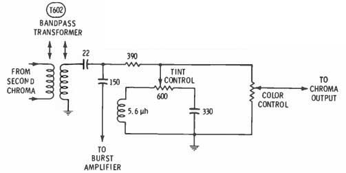
Fig. 23 Tint control adjustments do not change the amplitude of the burst
or the 3.58-MHz reference oscillator signal in the Sylvania 012 chassis; instead,
it uses the chroma phase-shifting network in the tint control shown here.

Fig. 24 Transistors are used in the "X" and "Z" demodulator
circuits in the Sylvania D12 chassis. Their supply voltage is only 20 volts.
Sony
A 12" Trinitron color picture tube is used in the Sony KV-1210U chassis, which employs 44 transistors, 35 diodes and I high-voltage rectifier tube. The Trinitron color picture tube has only one electron gun, although it does have three cathodes, to which are applied the b-w video and chroma signals. The manufacturer claims twice the brightness of conventional three-gun tubes, and much simpler convergence adjustments.
Generation of the 3.58-MHz reference carrier also is accomplished in a different way in this chassis.
The burst rings a 3.58-MHz crystal, and this nearly continuous signal is used to synchronize a 3.58-MHz multivibrator oscillator. The oscillator signal is fed through a hue control (see Fig. 20), an amplifier and a tuned transformer before it is applied to the three balanced diode demodulators.
One diode demodulator is used for each primary color. These demodulators, shown in Fig. 21, are similar to the ones used in some GE receivers, but do not have balancing controls. Matrixing is accomplished in the demodulator rather than at the picture tube; the video is applied to the junction of the two diodes and will go through either diode that is forward biased. Video and chroma both must be matrixed and brought to the CRT cathodes because there is only one control grid.
Fig. 22 shows more of the blue channel (the other two channels are nearly identical to this one), in which an emitter follower, Q4O1, drives the base of the power output stage through the adjustable control labeled "blue drive". There are no individual screen voltage adjustments because there is only one screen grid, so the three drive controls and the three background controls are used to obtain correct screen color and b-w tracking.

Fly. 25 Color-killer action in the Zenith 14A9C51 chassis is rather devious.
ACC action changes the plate and screen voltages of V201B, the first color
amplifier; these voltages, in turn, determine the bias on Q206, the second
color amplifier. During b-w reception, the plate voltage on V201B is very low
and the base of Q206 is less positive than its emitter; thus, the transistor
is reverse-biased. With strong color tuned in, the plate voltage of V201B will
be +140 volts or higher, and Q206 will have normal bias for good amplification.
The color-killer diode is not essential for operation of this circuit, but
is a refinement to prevent excessive forward bias on Q206. This is done by
clamping the voltage at test point "K" to +24 volts whenever the
voltage tries to exceed that limitation.
Sylvania
The Sylvania D12 ( Gibraltar) chassis is another hybrid. It has 24 transistors, one IC and 9 tubes.
Generally speaking, tint-control circuits that tune a burst or 3.58 MHz reference signal transformer have one major drawback: A large amplitude change in the signal during tint adjustments.
Sylvania changes the tint in the D 12 chassis by varying the phase of the chroma signal between the bandpass transformer and the color control (Fig. 23). The 600-ohm tint control, in effect, switches in a capacitor or a choke to make the phase lag or lead, and a 390-ohm resistor isolates the variable part of the circuit from the burst.
Transistors are used as demodulators in the D12 chassis, as shown in Fig. 24. Chroma is applied to the bases, while a 3.58-MHz reference signal with a 90-degree phase difference is supplied to the emitters. The demodulator collector circuits and the following-Y amplifier circuits are nearly identical to previous tube versions.

Fig. 26 Matrixing of the b-w and chroma signals traditionally has been accomplished
in the picture tube. (A) A block diagram of the traditional system, with the "Y" or
video voltage applied to the three cathodes and the R-Y, B-Y and G-Y chroma
signals connected to the red, blue and green CRT grids, respectively. (B) In
the Quasar, Sony and now the Zenith 12Al2C52 chassis, the video and chroma
signals are matrixed and then applied to the cathodes of the CRT.

Fig. 27 In the red channel of the Zenith chassis, the chroma signal from the
IC demodulator goes to the base of Q205, while the video signal goes to the
emitter. The true red signal (not R-Y) is taken from the collector of Q205
and is routed through the red gain control to the red cathode of the CRT.
Zenith
A different kind of color killer is used in the Zenith 14A9C51 chassis. The schematic of this circuit is shown in Fig. 25. Assume that the set is tuned to a b-w program. Q206, the second color amplifier, is biased to cut-off by the 12.4 volts applied to its emitter by the voltage-divider action of the two 2.2K-ohm resistors between the +24-volt source and ground. Its base voltage is only 11 volts because of the low source voltage of +75 volts at the screen of V201B. Thus, the transistor is 1.4 volts reverse biased. When color is tuned in, the killer/ACC detector has an output of several volts negative, which reduces the gain of V201B and causes the screen voltage to rise above + 140 volts. This increases the base voltage of Q206 to about + 19.5 volts; the resulting emitter raises the emitter voltage to about + 19.2 volts, and the transistor amplifies. CR205, the killer diode, has two functions: One is to make sure that the anode voltage does not increase above +24 volts. If it does, the diode conducts and clamps the circuit to the +24 volts as protection and bias limiting for the second color IF amplifier transistor.
The other function is to provide a convenient way to defeat the color killer so that the second color amplifier can conduct: short across the diode from test points "K" to "KK". The first commercial color receiver ever placed on the market in 1954 had a very complex matrixing system to combine the chroma and video signals into three pure primary color signals that were fed separately to the three picture tube grids. This can be called pre-CRT matrixing. RCA used this system in the 1954 and 1955 model color receivers, then it was not used for years until Motorola updated it in the Quasar chassis.
Fig. 26A shows a block diagram of the traditional system of matrixing in the picture tube by feeding the video to the CRT cathodes and the chroma-Y signals to the three control grids. There apparently are no basic drawbacks in this system, except that four powerful amplifiers are necessary to completely modulate the CRT current. In solid-state circuits, this means that these amplifiers must operate with 160 to 200 volts on the collectors; consequently, elimination of the video output stage seems a good idea.
Also, the new Trinitron color picture tube demands pre-CRT matrixing. Fig. 26B is a block diagram of a system in which the chroma/video matrixing is accomplished ahead of the picture tube.
The schematic of the red amplifier channel in the Zenith 12A12-052 color chassis is shown in Fig. 27. The green and blue channels are similar to the red. From the IC, the R-Y signal is connected to the base of 0205. Video from the emitter of the third video amplifier is applied to the emitter of Q205. The true input to 0205 is between base and emitter, and the transistor sees the resultant voltage as though the video had been inverted in phase and applied to the base. The red signal on the collector includes both video and chroma and is applied to the CRT red cathode. The CRT grid has no signal on it, just a DC voltage to maintain normal brightness.
Conclusion
The preceding paragraphs have described briefly the most revolutionary designs we are aware of in the 1970 color chassis. For additional knowledge of the operation of these new circuits, we suggest that you obtain the manufacturers' literature about the circuits you are interested in and, whenever possible, attend manufacturers technical training sessions-in most cases such sessions are open to all electronic technicians and there is no charge.