BRIDGE CIRCUITS ARE mostly used in measuring instruments, but they are also employed in sensing and controlling. They are the electronic equivalent of a pair of scales, in which some un known quantity is balanced against the known weights. When a bridge is "balanced" its two sides are at the same potential, so no current lows through the indicating device connected between them. Consequently it shows zero, or a " null."
When a resistor, capacitor or inductor of unknown value is to be measured on a bridge, known values of resistance, capacitance or inductance are used as " weights " to balance the bridge, and from these values the value of the unknown is found.
Wheatstone Bridge
Bridges are frequently, though not always, shown in the diamond pattern of Figure 10.1. This is the Wheatstone bridge. It is the only bridge that can operate on DC, and then only for measuring resistance.
In Figure 10.1 (a) resistors R1, R2 and R3 are bridge resistors, and Rx is the " unknown" resistor whose resistance is to be measured. In (b) the same layout is illustrated, but rotated 90 degrees clockwise.
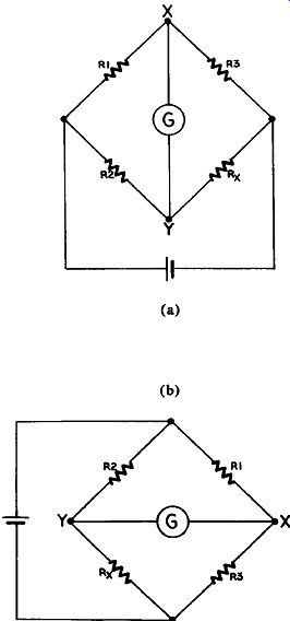
Figure 10.1 Wheatstone Bridge
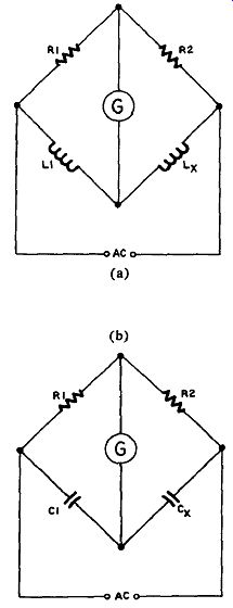
Figure 10.2
Either way is possible for this layout. R1 and R3 are a voltage divider, and so are R2 and Rz. Current from the battery flows through each divider, and the voltages at X and Y will be according to the ratio of the resistances. If R1 and R3 are equal the voltage at X will be half the battery voltage, and if R2 and R* are equal the voltage at Y will also be half the battery voltage. X and Y will be at the same potential, so no current will low between them. The galvanometer, G, connected between them will give no indication. We say the bridge is "balanced" or the galvanometer is "nulled," or indicates a null.
Since R* is unknown R2 is made variable so that it can be adjusted to balance R*. It may be an assemblage of fixed resistors, a potentiometer, or both. R1 and R2 together must provide resistance such that the right current lows through R2 and R* to allow the voltage at Y to change readily as R2 is adjusted, so that an accurate reading can be made. The value of R2 is read from the dials of the selector controls, and is of course the same as that of R*.
LC Bridge
The LC bridge is a Wheatstone bridge adapted for measuring inductances and capacitances. Since we are now measuring reactance we have to use AC instead of DC.
In Figure 10.2(a) the unknown inductance is balanced against a known inductance just as in the resistance bridge. However, the dials giving the reading are calibrated in henries, millihenries and micro henries instead of ohms.
In Figure 10.2(b) a bridge for measuring capacitance is shown, operating in a similar way.
The function of R1 and R3 (or R2) is the same for all three bridges.
Owen Bridge
In the Owen bridge (Figure 10.3) R1 and R3 of the Wheatstone bridge are replaced by C1 and C2. This bridge measures inductance more accurately because it measures both the inductive (Lx) and resistive (R*) components of an inductor. C1 and R2 are each variable, and must be adjusted to obtain a null. In another version a variable resistor in series with L* is used instead of C1.
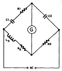
Figure 10.3 Owen Bridge
Maxwell Bridge
The Maxwell bridge (Figure 10.4) is very similar to the Owen, and is used for the same purpose. It is a partial return to the Wheatstone bridge, since R1, R2 and R3 have been modified only by the addition of C1 in parallel with R2. The resistive part of the inductance is there fore measured as in a Wheatstone bridge, but C1 adapts it for measurement of inductance also.
Hay Bridge
The Hay bridge (Figure 10.5) is similar to the Maxwell, except that C1 is now used in series with R2. This arrangement works better for inductors with large inductances.
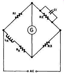
Figure 10.4 Maxwell Bridge
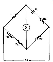
Figure 10.5 Hay Bridge
Resonance Bridge
In this bridge (Figure 10.6) the capacitor C1 is tuned to resonance with the unknown inductor. This serves to measure its inductance, and at the same time leaves only the resistive element (at resonance a series resonant circuit has no reactance), which is balanced by R3, as in the Wheatstone bridge.
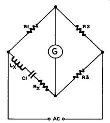
Figure 10.6 Resonance Bridge
Schering Bridge
The Schering Bridge (Figure 10.7) measures capacitance. Its operation is similar to the Maxwell bridge, except that C2 replaces R2. The unknown capacitor has a resistive component in its reactance in the same way an inductor does.
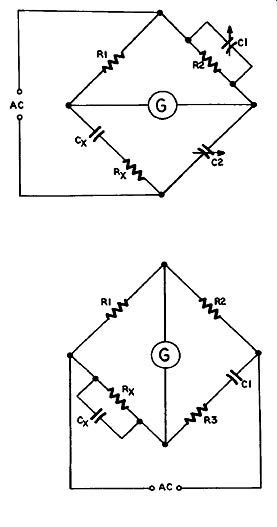
Figure 10.7 Schering Bridge; Figure 10.8 Wien Bridge
Wien Bridge
The Wien bridge (Figure 10.8) is used for measuring frequency. It is similar to the Schering bridge, and can be used to measure capacitance. However, if instead of an unknown value of capacitance at C* a known value is chosen to balance that of C1 at the frequency being measured, and if R3 is also adjusted to balance the resistive element of Cx, then the frequency of the AC signal applied to the bridge may be determined.
-------------------