JUST AS A THERMOSTAT senses a drop in temperature and signals the furnace to turn on, so a synchro generator senses a change in the mechanical position of something, and sends a signal which actuates the corrective action. Synchros are used extensively in industrial controls, in the guidance systems of ships, planes and rockets, and in other applications too numerous to list.
Servomechanisms
A household thermostat has a fixed output, and is called a regulator.
A more sophisticated control system that adjusts its output automatically in accordance with its input is called a servomechanism. A well known example is the governor on a steam engine, in which an increase in speed above that set results in a reduction in throttle opening, and vice-versa, to maintain an even rate.
Synchro Systems
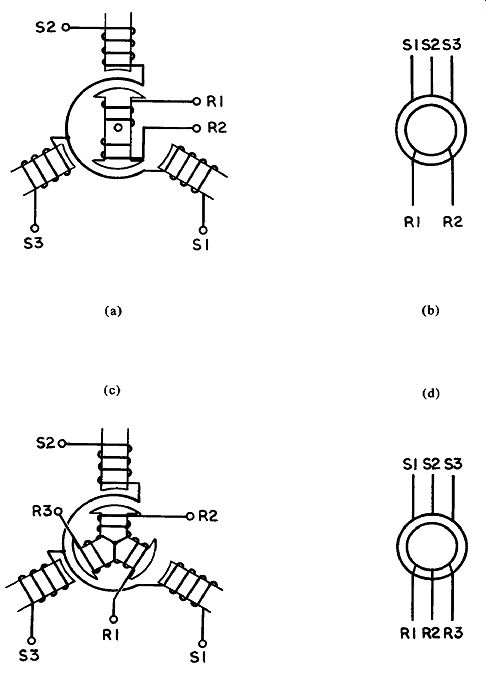
Figure 11.1 Synchro Construction
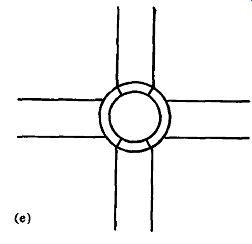
Figure 11.1 Synchro Construction (cont’d.)
A synchro system is a feedback system in which synchros are used.
A synchro (sometimes called a selsyn) resembles a small electric motor. Three field coils mounted in a cylindrical case surround an armature [Figure 11.1(a)]. The field coils are called stator windings, those on the armature are called rotor windings. However, when an alternating current of 60 or 400 hertz (depending on synchro type) is applied to the rotor winding the armature does not rotate. Instead its magnetic field induces voltages in the three stator windings. Because each stator winding makes a different angle with the rotor winding a different voltage is induced in each.
These voltages rise and fall as the armature is turned to different positions. They are transmitted separately to another synchro, and applied to its corresponding stator windings. The composite magnetic field generated by these windings interacts with that generated by the second synchro, s rotor winding, which is also excited by 60 or 400 hertz AC, and the pushing and pulling of the lines of force turn the second synchro's rotor to the same position as that on the first synchro. If the first synchro is rotated to a new position, the second takes up the same position also.
Synchro Schematics
The different types of synchros used in synchro systems are listed at the top of the next page.
Those in the first group listed are constructed as shown in Figure 11.1(a), with symbol as illustrated at (b). Transmitters and trans formers also used to be known as generators or masters, and receivers as motors or slaves. These terms may still be found in some schematics.
Synchro Systems Synchro Type
Identification Letters
Control Transformer Torque Receiver Control Transmitter Torque Transmitter
CT TR CX TX
Torque Differential Receiver TDR
Control Differential Transmitter CDX
Torque Differential Transmitter TDX
The simplest synchro system has a transmitter and receiver connected as in Figure 11.2(a). Whatever position is set on the transmitter is assumed by the receiver. The receiver also rotates in the same direction as the transmitter. If the wires are crossed as in Figure 11.2(b) the receiver turns in the opposite direction to the transmitter. The second group of synchros has three rotor windings. Figure 11.1(c) shows that in the differential type the armature is wound in the same way as the stator. This allows it to receive two inputs and combine them algebraically. The symbol is shown in Figure 11.1 (d).
In Figure 11.3(a) a torque transmitter (T) signals the position of its rotor to the stator of the torque differential transmitter (D). Voltages are induced in the three rotor windings of D which are a combination of those transmitted from T and those resulting from the position of D' s rotor. The voltages transmitted to R will result in the receiver's rotor assuming a position which is equal to the difference between the angular positions of T and D, or R = T - D.
In Figure 11.3 (b) the leads have been crossed. In this configuration the position assumed by the receiver will be equal to the sum of the angular positions of T and D, or R = T + D.
In Figure 11.3(c) the differential synchro is the receiver. Its rotor will assume a position equal to the sum of the angular positions of both transmitters.
The difference between control and torque transmitters and receivers is that control types have more turns and a higher impedance. This improves accuracy, but because current is minimal there is insufficient power output to actuate a control. An amplifier is needed to introduce power into the circuit. Accuracy is also improved by connecting a triple capacitor across the stator leads of a control transformer, as shown in Figure 11.4, to cancel stray magnetizing currents in the stator wind-
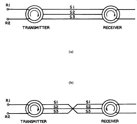
Figure 11.2 Synchro System
Figure 11.3 Differential Synchro System
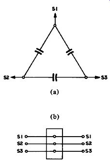
Figure 11.4 Synchro Triple Capacitors rings. In this figure (a) is the electronic
schematic and (b) is the mechanical symbol.
Resolver
The synchro transmitters we have been discussing operate by generating voltages in their three stator windings that vary according to the angle of the rotor. If the rotor is turned through 360 degrees each stator voltage goes through one cycle of a sine wave with a maximum voltage of 90 volts, where the rotor excitation voltage is 115 volts.
However, as the three stator windings are spread equally around the synchro casing the phases of the three signals are staggered 120 degrees. The receiver operates by reproducing the magnetic fields of the transmitter.
The synchro thus has three poles. A resolver is like a synchro, but with many more poles. As its rotor turns and passes each pole a sine-
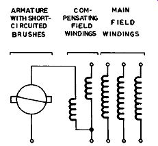
Figure 11.5 Amplidyne (rotary amplifier)
The amplidyne is really a generator in which weak input current changes in the field coils (from a synchro, for instance) are converted to powerful output current changes in the armature by a kind of trans former action known as armature reaction.
-------------------