1. The Meaning of Oscillation
The oscillator is almost as old as radio itself. In every generation since Hertz transmitted electrical energy across a room, amateur experimenters and professional engineers have labored to improve oscillatory circuits along various lines toward the end of meeting the increasingly rigorous demands which the passing years impose.
Oscillation is a process in which an alternating voltage is produced as the result of the conversion of energy from one form to another through the use of some reciprocating agency. For example, the vibrator in an automobile radio is a mechanical oscillator that converts the d-c power of the car battery into higher a-c voltages and currents with the aid of a power transformer.
When used in association with vacuum tubes and other electronic gear, the word oscillation refers to the action in a generator of a-c power in the form of pulsating electron streams. The a-c power is generated in association with resonant circuits composed of inductors and capacitors, or time constant circuits made up of resistive and capacitive components. In this guide we shall be concerned only with L-C circuit oscillations in the radio-frequency spectrum; R-C and low-frequency oscillators are covered elsewhere in this Review Series.
2. Applications of Oscillators
Virtually every phase of electronic industrial control and plant operation, communication, electronic warfare, radio aids to navigation, and many fields of research rely upon oscillators in one form or another. A general list of applications would be endless.
The discussion of crystal oscillators to follow will point to uses of this device particularly in communications, inasmuch as it is this field in which crystal control finds its natural application.
3. Oscillator Performance Requirements
Radio operators and others who are directly associated with the performance of radio transmitters have found by experience that certain performance features are required in the transmitter as a whole to ensure optimum operation. The most important features are: frequency stability, power output, simplicity of operation, ruggedness and reliability, and continuous frequency coverage. The first two features not only are a matter of convenience, but must meet certain legal requirements of law and of the Federal Communications Commission (FCC) . Because the oscillator generates the r-f carrier for the whole transmitter, it also fully controls the frequency stability of the transmitter. In the other transmitter features listed above, the oscillator must harmonize with the design of the complete transmitter. Thus all the above features are important in oscillator design. Let us examine each feature individually.
Frequency Stability. This is by far the most important consideration in the design of oscillators for communication equipment. It is the ability of an oscillator to maintain the same frequency of oscillation under conditions of changing load, changing d-c supply voltage, changing temperature, changing barometric pressure, vibration and mechanical shock, external capacitance and inductance effects, and high humidity.
Power Output. An oscillator with high power output lends itself to the design of a simpler transmitter because it reduces the need for many cascaded radio-frequency amplifier stages. Thus, an important goal of the oscillator designer and builder is as much power output as possible without adversely affecting frequency stability. However, the two cannot usually be increased together.
Power output is normally sacrificed in favor of frequency stability.
Simplicity of Operation. Oscillators having a variety of frequency ranges may be designed with one, two, or even three different adjustments. Hence one of the criteria for judging the value of an oscillator is the number of desirable operating features for a given complexity of the adjustments.
Ruggedness and Reliability. These characteristics speak for themselves and are important factors in the choice of an oscillator for a given job. Although construction methods contribute more to achieving good performance in these respects, circuit design also makes an appreciable difference in many instances.
Continuous Frequency Coverage. The ideal oscillator would offer the feature of continuous tuning over a required band of frequencies. As a further requisite, the output power should re main constant throughout the tuning range. Few self-excited oscillators fulfill the latter requirements, but many come very close to it; in addition, practically all of them do permit continuous frequency coverage.
4. Self-Excited L-C Oscillator Characteristics
By virtue of its ability to amplify, a vacuum tube (or a transistor) may be used to produce sustained oscillations in an L-C circuit (usually referred to as a tank circuit) . To set up the conditions necessary for sustained oscillation, a tank circuit must be shock-excited into oscillation by a change in the current flowing through it; the oscillatory voltage thus developed must then be amplified by the tube, and a portion of the amplified power fed back to the oscillatory tank circuit to make up for the losses that occur there due to resistance, grid current flow, radiation, and loading. Because these losses may be made very small, particularly at the lower radio frequencies, a relatively small amount of feed back is all that is necessary, provided that it is phased properly to reinforce the oscillations.
The tube output may be coupled back to its input circuit by means of an inductive or capacitive network. In either case, when the coupling is correctly adjusted, the· feedback phase and amplitude cause sustained oscillations at a frequency approximately determined by the equation: f = f L C cps henries farads In Fig. 1 (A) is an inductive-feedback oscillator and (B) a capacitive type. In (A) the mutual inductance M is responsible for the feedback from plate winding L2 to grid winding L1. In (B) the component labeled A-B is the reactance which is common to both plate and grid circuits and which accounts for the feedback.
Oscillators such as these are capable of very large power output when used with appropriately large vacuum tubes; in both cases two initial adjustments are required: in the inductively coupled type (IA), the setting of C determines the frequency with a given tank inductance, L. The coupling between L1 and L2 influences the efficiency of operation; the adjustments on the capacitive feedback oscillator (IB) involve the proper ratio between C0 and CP to provide the grid with sufficient excitation for maintaining oscillations and further adjustment of both these capacitors to establish the desired frequency.
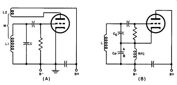
Fig. 1. Circuits illustrating inductive feedback (A) and capacitive feedback
(B).
Self-excited oscillators must be of special design to avoid poor frequency stability at the radio frequencies. They are subject to line voltage variations, changes in loading, atmospheric conditions, and mechanical shock; under each of these circumstances the frequency and output amplitude tend to fluctuate unless extreme care is taken in the design. Thus, except when elaborate design measures for stability are taken, these oscillators are not suitable for radio transmitters, for which the FCC has set up small frequency tolerances.
The crystal-controlled oscillator answers the demand for simplified design with extraordinarily high frequency stability; it is rugged, easy to operate, and in most cases thoroughly reliable.
Crystal oscillators cannot, however, be made to yield power output comparable with that of self-excited oscillators using large tubes and must, therefore, be followed by one or more radio-frequency amplifiers depending upon the power output requirements. This is not an important factor, however, because adequately stable self excited oscillators must operate at low power anyway. Nor does the crystal oscillator lend itself to continuous frequency coverage, although crystal switching is now a perfected art and does enable the operator to choose one of several frequencies within the same band without retuning the entire transmitter.
5. Quiz
1. Give six criteria for evaluating the performance of an oscillator.
2. What is meant by "frequency stability"' in respect to an oscillation
3. What is a "self-excited" oscillator?
4. Give the equation for calculating the frequency of oscillation .
5. What would be the frequency of oscillation of a theoretically resistance-free tank circuit whose inductance is 70 µhenries and whose capacitance is 200 µµf?
6. Draw a diagram of an inductive feedback oscillator.
7. Draw a diagram of a capacitive type feedback oscillator. Modify this diagram and that of question 6 to change these circuits to crystal-oscillator circuits.
8. List the characteristics governing adjustment of the oscillators whose circuits are drawn in answer to questions 6 and 7.
9. Enumerate two disadvantages of the self-excited type of oscillator.
10. List the desirable features and the disadvantages of a crystal controlled oscillator.