6. Piezo-Electric Effect
The remarkable property of certain crystalline substances, notably quartz, in exercising control over the frequency of an oscillator arises from a relationship between electrical stress and mechanical movement that exists in such crystals. When a thin, flat section is cut from a "mother stone" (Fig. 2) along certain dimensions to be discussed later, the plate thus obtained actually vibrates at a high frequency rate when properly excited electrically.
The phenomenon of the appearance of electrical charges on the faces of the plate, resulting from physical compression or distortion is called the piezo-electric effect.
Piezo-electricity is common to crystals such as Rochelle salts, tourmaline, and quartz. Any one of these may be used for frequency control. Quartz, however, has completely eclipsed the others in practical work. It does not fracture as easily as Rochelle salts while under stress nor is it affected by moisture, high temperature, and high humidity as are Rochelle salt crystals. Quartz is much more sensitive electrically and less costly than tourmaline. A crystal of Rochelle salts is capable or producing much greater piezo-electric voltages than quartz and for this reason is utilized in the manufacture of crystal microphones, in which the mechanical forces are not as great as they are in crystal oscillators. Tourmaline, on the other hand, is mechanically stronger than quartz and does not have to be ground as thin as quartz for a given oscillation frequency. however, because of its insensitivity, it is used only at very high radio frequencies where a fundamental quartz crystal would be impractical. The popularity of quartz may also be attributed to its low cost and its ready availability.
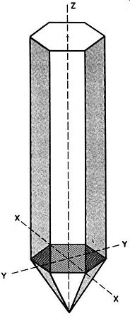
Fig. 2. Quartz crystal, from which oscillator plates are cut.
7. Crystal Characteristics
Quartz occurs naturally in the form of crystals that vary in size and shape, but the ones chosen for their piezo-electric proper ties are generally hexagonal in cross-section, having six side faces as shown in Fig. 2. Crystals of this form are usually capped by hexagonal pyramids at one or both ends, the pyramid having six cap faces.
To differentiate between the various directions within the crystal, lines may be drawn as shown in the figure, joining different important points. These lines, called axes, are conventionally labeled as shown in the figure.
The X axis joins two points at opposing corners of the hexagon. There are three such axes although only one is shown in the figure for the sake of clarity. The lines joining the remaining two pairs of corners are called X' and X". The X axes are termed the electrical axes because the greatest electrical sensitivity lies along these lines.
The Y axis joins two faces at opposite sides of the hexagon, intersecting the face planes at right angles. Again, since there are six faces, there are three Y axes (Y, Y', and Y") called the mechanical axes.
There is only one Z axis. Referred to as the optical axis, it passes longitudinally through the center of the mother stone and intersects all the X and Y axes perpendicularly.
The process of making a complete crystal unit from a mother stone involves proper orientation of the plate with respect to the three axes, cutting, grinding to the thickness needed to establish a desired frequency, and mounting in a suitable holder.
8. Modes of Vibration
When an alternating voltage is applied across a quartz crystal so that there is a component of electric stress (electrostatic field) along one of the X axes, mechanical strains or dimensional changes occur along the Y axis that is perpendicular to the X axis in use.
When the electric stress alternates, the variations in size or shape of the plate likewise change so that the crystal vibrates mechanic ally. At a certain frequency of vibration, determined by the dimensions of the plate, the type of cut, the kind of holder or mounting, and other minor factors, the plate comes into mechanical resonance like a pendulum that is periodically prodded at exactly the right instant. At resonance, the crystal vibration may become very great in amplitude-great enough, in fact, to cause a fracture if the vibration is uncontrolled.
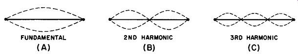
Fig. 3. Modes of vibration of a violin string.
Even a simple thing like a vibrating violin string may oscillate in different modes; it may, for instance, move up and down as a whole (Fig. 3A) , in two parts (Fig. 3B) , in three parts (Fig. 3C) , or in other configurations. When vibrating as a whole, the musical note is the lowest in pitch that this particular string can produce and is called the fundamental tone. The two-part motion at twice the frequency of the fundamental tone is the first overtone or second harmonic; the vibration in three parts, having a frequency three times that of the fundamental, is the second overtone or third harmonic. In the interests of consistency, reference will be made only to harmonics in this discussion; it should be noted that this is appreciably simpler to interpret because the harmonic number is equal to the multiple of the fundamental frequency. That is, harmonic number = number of times fundamental is multiplied.
Depending upon the orientation of the crystal cut, a given plate usually vibrates in one particular mode, but various modes are possible under different conditions of cut, grinding, mounting, and excitation.
Flexure Mode (Fig. 4A). This kind of vibration is similar to that of a vibrating string producing its fundamental tone. When oscillating in this mode, a crystal produces an a-c voltage at its lowest characteristic frequency.
Shear Mode (Fig. 4B and 4C). As the name implies, this mode of vibration tends to shear the crystal along either its thickness (Fig. 4B) or along the face (Fig. 4C) . The resulting distortion may be visualized as one in which the rectangular cross-section is altered to a regular parallelogram whose corner angles vary from some acute angle through 90 degrees to a corresponding obtuse angle as shown in the figures. This mode is employed chiefly at high frequencies because, in this portion of the spectrum, quartz vibrating in this mode can be given good temperature-frequency stability (low temperature coefficient). Longitudinal Mode. This is sometimes called the compression al mode. As Fig. 4D shows, the vibration occurs in such a manner as to periodically elongate and simultaneously reduce the thickness of the plate. This is a piston- like action which, in addition to its use in frequency control functions, is now being applied to the design of ultrasonic crystal transducers. This mode of oscillation is especially useful in the frequency range between the flexure mode (very low frequencies) and the shear mode (high frequencies). Torsional Mode. This mode is characterized by a twisting motion around the long axis of the plate. It is of historical interest only, having been used for very low frequencies in the early days of crystal control. It is no longer used in this country.
Activating potentials are normally applied to crystals at two points, as shown in Fig. 4E. In certain applications, however, where a low-frequency flexure mode is to be used, a special mounting, in which potentials are applied at four points as shown in Fig. 4F, is necessary.
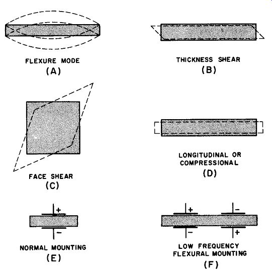
Fig. 4. Mod .. and mountings for oscillating crystals.
9. Fundamental Crystal Oscillator Circuit (Basic Miller Oscillator)
A triode amplifier with a resonant circuit in its output as well as its input circuit constitutes the standard tuned-plate, tuned-grid (TPTG) oscillator (Fig. 5) . Positive feedback from the plate to the grid occurs through the grid-to-plate capacitances of the triode.
Substituting a quartz crystal for the L1-C1-Cg combination produces sustained oscillations if the L2-C2 tuning circuit is resonated to a frequency at or very close to the natural frequency of the crystal.
The modified circuit is shown in Fig. 6. Here the crystal is mounted between two flat, carefully machined electrodes, which hold it in place and permit the application of radio-frequency potentials de rived from the oscillatory plate tank circuit.
Thus, with this substitution made, the tuned oscillatory electrical circuit consisting of grid tank coil, grid tank capacitor, and grid coupling capacitor has been replaced by a mechanically resonant, oscillatory crystalline device in a mechanical mount. It is essential to recognize that this concept is of the utmost importance in the circuit analysis presented later in this Section.
10. Circuit Operation
It was stated in Par. 4 that sustained oscillations may be explained on the basis of three phenomena: (a) shock excitation of the L-C tank by some change in tube or circuit voltage, (b) amplification, and (c) positive or in-phase feedback from output to input circuit.
The oscillator whose circuit is given in Fig. 6 may be analyzed according to these actions. When plate power (B+) is applied by closing the switch, the triode becomes conductive and a surge of plate current starts to flow through L2, causing a magnetic field to build up around the coil. As the switch is closed, the rapid rate of increase of the intensity of the magnetic field induces a voltage by self-induction across L2, causing C2 to charge. As the plate current approaches maximum and tends to stabilize, the field tends to be come static and the inductive voltage drop disappears. It is at this point that the true oscillatory process begins, with oscillations taking place in L2-C2 at the resonant frequency.
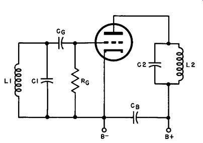
Fig. 5. TPTG oscillator circuit.
As C2 begins to discharge to start its normally damped oscillatory cycle, the changing potential on this capacitor is transferred electrostatically through the tube's grid-plate capacitance and placed across the crystal. As a result, the crystal distorts physically in the particular mode for which it was designed. Because this distortion produces a voltage across the crystal faces, and because this voltage is fed to the control grid of the tube, the crystal now constitutes the input circuit-a circuit that develops a voltage whose frequency is determined by the crystal and holder constants.
Thus, the input voltage from the crystal is amplified by the tube, a part of the output energy being used to sustain plate-tank oscillations and a smaller part being fed back to keep the crystal vibrating. The action is identical with that of the TPTG oscillator except that the crystal has replaced the resonant circuit and the grid-coupling capacitor.
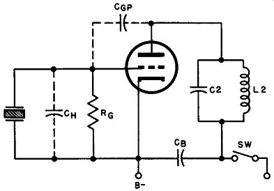
Fig. 6. TPTG circuit with crystal substituted for grid tank.
Figure 6 shows that Cgp, the capacitance between grid and plate inside the tube, may be simulated by an actual capacitor drawn outside the envelope and that the capacitance between the holder electrodes may be shown as a capacitor Cgp in parallel with the crystal.
While an oscillator is operating, it creates its own bias by grid conduction. As the crystal vibrates and generates piezo-electric potentials, the control grid is driven into conduction on positive peaks, current flows downward through Rg, the bias voltage developing across this resistor and C_H.• A more extended discussion of crystal oscillator bias appears later in this Section and in the practical circuits presented in Section 4.
11. Equivalent Circuit of the Crystal Oscillator
The very close electrical resemblance that a crystal bears to a tuned circuit (see Par. 8) makes it possible to analyze circuit operation on the basis of an equivalent circuit, in which the crystal is visualized and discussed as though it were composed of resistance, capacitance, and inductance.
Frequency versus impedance response curves (Fig. 7) indicate that a crystal in its holder or mounting behaves like a series resonant L-C circuit with an extremely high Q (XL/ R) . Examination of the curve discloses that the impedance of the crystal unit is close to zero at the resonant frequency, rising to a peak at a second frequency called the anti-resonant frequency. The reduction of impedance with rising frequency in the illustration is shown between the ordinate axis and fr (resonant frequency) and the sharp rise of impedance between fr and fa (anti-resonant frequency). The steep slope of the sides of the curve and the large differential between the impedance at fr and fa immediately suggest that the Q is high; that view is supported by the great difference between the pure resistance (R in the figure) and the total maximum impedance at the peak of the curve.
Thus, the equivalent circuit of a crystal consists of an inductance (L), a series capacitance (C), a series resistance (R), and a shunt capacitance (C_H), representing the capacitance of the crystal holder. (See Fig. 8.) It is to be assumed that the frequency at which L and C are in resonance is also the frequency of mechanical resonance of the crystal. The electrical energy consumed by the equivalent L-C-R circuit is that which the circuit supplies to maintain crystal vibration; below resonance, the arrangement is capacitive in nature-as in any series resonant circuit-because the equivalent capacitive reactance is larger than the equivalent inductive reactance at the lower frequency; above resonance, the circuit is inductive. At resonance, of course, the reactive components disappear and the crystal is purely resistive.
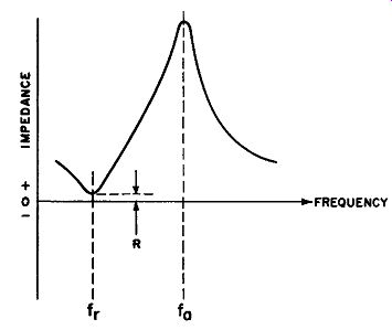
Fig. 7. Impedance versus frequency characteristic of a crystal.
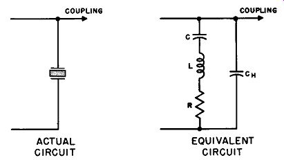
Fig. 8. Actual and equivalent circuits of a crystal.
The magnitudes of L, C, R, and CH that enter into equivalent electrical network are determined primarily by the thickness of the crystal, the orientation of the plate to the crystal axes, the type of mounting, and the mode of vibration. Comparing the electrical constants with the mechanical characteristics of the crystal, it may be demonstrated that: L is equivalent to the vibrating mass of the plate C is equivalent to the stiffness or mechanical compliance
R is equivalent to the losses due to friction and acoustic radiation
For a typical 5- mHz crystal representative values for these constants might be:
L .05 henry C = .02 µ.µ.f R = 50 ohms
The Q of this particular crystal is computed as follows:
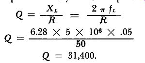
Hence, when one recalls that a Q of 100 for an ordinary L-C resonant circuit is considered high, a value such as that obtained above is quite remarkable.
One other important fact may be gleaned from the equivalent circuit: as shown in Fig. 8, the point at which coupling to the external circuit (to the grid of the vacuum tube in the case of the Miller oscillator) occurs is the junction between C and CH. The extent of coupling is obviously dependent upon the ratio of these capacitances, since they form a voltage divider with the largest potential being developed across the smaller capacitance (the larger capacitive reactance). The coupling voltage appears across CH and, for the typical crystal discussed in this paragraph, CH might be approximately 12 µµf. Thus, the ratio is: C/CH = .02/12 = .002
This figure is very small and signifies that only a tiny fraction of the total crystal energy is coupled to the amplifier. Loose coup ling like this makes the crystal relatively independent of load conditions-another very important favorable characteristic.
12. Crystal Oscillator
Bias In general, there are several ways in which grid bias is sup plied in vacuum tube circuits:
a. Fixed bias, from a source independent of the tube's immediate circuit section. Examples of such sources are bias power supplies and bias batteries. In such an arrangement, the bias voltage value is not affected by actions in the tube's immediate functional circuit.
b. Cathode bias, in which bias is the voltage drop across a resistor connected in series with the tube's cathode return lead. A bypass capacitor is usually connected across the cathode resistor to shunt a-c signal from the bias voltage. In this arrangement, bias voltage is proportional to plate current plus grid current (plus screen grid current in tetrodes, beam tubes, and pentodes). Thus, if plate current tends to become excessive, bias increases and tends to compensate and protect the tube.
c. Grid leak bias, which is of two types: (1) In amplifiers in which there is no grid current resulting from signal drive, a very high resistance (10 megohms or greater) is sometimes connected between grid and cathode. The minute current from the grid due to the velocity of electrons in the tube's electron stream striking it produce sufficient voltage drop in the grid resistor to develop required bias. Signal drive must be kept within the bias range and not drive the grid positive.
(2) In amplifiers and oscillators in which there is grid current from signal voltage, a moderate value of resistance is connected between grid and cathode. This rectified signal grid current passes through the grid resistance, producing a voltage drop, which is the bias. The development of bias by this method is illustrated in Fig. 9.

Fig. 9 How grid-leak bias Is developed from grid circuit.
In oscillators, fluctuations of load or supply voltages may cause a temporary drop of grid excitation voltage. If fixed bias (Par. 11a. above) were employed, any lowering of grid signal voltage would lower plate signal voltage. Then the feedback would decrease and cause even lower grid signal voltage. Thus any lowering of signal in the oscillator would be accelerated and the circuit might rapidly go out of oscillation. Also, it would be difficult to get oscillations started, because there would be no grid current until the signals in the circuit were almost of normal strength. The oscillator would thus not be "self-starting." For these reasons, fixed bias is never used in practical oscillator circuits for the complete bias supply.
Cathode bias varies with plate (or more exactly, cathode) current. Grid current also contributes slightly, but is so much smaller than plate current (usually) that bias is primarily affected by the latter. When a cathode-biased oscillator is turned on, full plate current starts to flow and full bias is established, preventing start of oscillations. Without oscillation, plate current stays at full value and bias is fixed, and would not be affected by a signal voltage even if one were present. Thus, cathode bias alone is not suit able for oscillators, although it is occasionally used with grid leak bias, to protect the tube against excessive plate current.
Grid leak bias of the very high resistance type [C (I) above] is not suitable for ordinary oscillators, because it cannot be used with the signal current flow required in oscillators.
The other type of grid leak bias [C (2) above] can exist only when there is a grid signal present. This means that when the oscillator is first turned on, there is zero bias on the tube. Grid current and oscillation can begin immediately, making the oscillator fully self-starting. In addition, when the amplitude of oscillations tends to become excessive, the increase of grid current increases bias and reduces the tube gain, compensating for the tendency toward amplitude increase. Similarly, a tendency toward lower than-normal amplitude lowers bias, increasing tube gain and compensating for the fall-off tendency. The oscillator thus becomes to a large extent "self-regulating" as well as self-starting. For these reasons, grid leak bias is virtually always used in oscillators.
The operation of most r-f oscillators is of the class C type. In fact, an oscillator can be quite accurately pictured to be a class C amplifier whose output circuit is appropriately coupled to its in put circuit. Operating class C, an oscillator employs a rather high value of bias, approximating twice the cutoff value. Without the feedback signal, there would be no plate current at this bias. But as mentioned above, the bias is initially zero, and builds up with the signal. When oscillations have built up, the grid signal is strong enough to more than overcome the full bias and drive the tube into both grid and plate conduction. In so doing, the grid signal passes the transconductance (Gm) of the tube from zero up to a high peak value at the peak of this grid signal. The plate current flows only during the relatively short intervals when the grid is driven more positive than the cutoff bias, and this accounts for the high efficiency derived from class C operation.
13. Crystal Oscillator Power Output
The power output obtainable from a crystal oscillator is limited by two factors:
a. Heating of the crystal due to large r-f currents at high frequencies.
b. Strains set up by mechanical vibration of the crystal at lower frequencies.
When the aim is to obtain high frequency stability, heating in the crystal is intolerable because it causes a frequency drift that may be appreciable even with special crystal cuts having low temperature coefficients. On the other hand, strong mechanical strains are apt to fracture the crystal if allowed to continue for any length of time.
With these limiting factors taken into account, present practice calls for the use of low-power-output crystal circuits using very loose coupling to the crystal to keep crystal current down to a minimum. In modern transmitters, Class C r-f amplifiers are used to increase the power output to the desired level.
14. Tuning and Measurement Procedure in the Basic Crystal Oscillator
The tuning procedure used with the basic crystal oscillator en tails two current measurements, plate current and rectified grid current (Fig. 10) , both of which are in the order of milliamperes (d-c) in practical equipment. The plate circuit milliammeter provides an indication of average plate efficiency and should read as low as possible while the oscillator is stable in operation as explained below; the grid circuit milliammeter gives a direct current reading, which is a measure of the crystal excitation.
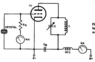
Fig. 10. Basic crystal oscillator circuit showing grid and plate current indications
useful
In tuning.
Most operators apply plate power with the tuning capacitor fully meshed; at maximum capacitance, the plate current is high (point A in Fig. 11) so that tuning must he deft and quick if the tube is to be protected against excessive heating. The capacitor is then swung outward toward lower capacitance and, just about at the resonant frequency, the plate milliammeter will show a sudden dip in its reading. At the same instant, the grid meter will begin to read the rectified grid current. The capacitance should be further reduced slightly to bring the operating point up slightly on the curve, as shown in Fig. 11; this provides good stability without much loss of efficiency and is highly advisable, because leaving the capacitance at the peak of the dip sets up hypercritical conditions which may cause the oscillator to be erratic, especially if it is being keyed.
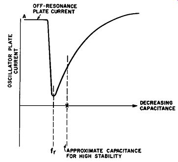
Fig. 11. Variation of plate current in crystal oscillator as tuning capacitance
is varied.
In most instances, the grid meter may be replaced by a small 6-volt pilot lamp, once the oscillator characteristics have been determined. In this connection, it not only offers a visual indication of the degree of excitation but also serves as a fuse that protects the crystal against r-f overload and possible fracture.
When a crystal oscillator is coupled to a radio-frequency amplifier, the tuning curve broadens and flattens simultaneously, al most eliminating the critical point entirely. It is still recommended practice, however, to detune even a loaded oscillator in the direction of reduced capacitance (higher frequency) to achieve maximum stability.
15. QUIZ
1. What is meant by the Piezo-electric effect? Name three substances exhibiting this property.
2. Sketch a quartz crystal of the hexagonal cross-section type. Show clearly the X, Y, and Z axes of this crystal.
3. Which axes are the "optical axes"? Which are the "mechanical axes"? Which are the "electrical axes"?
4. What is meant by "fundamental tone," "second overtone," and "third harmonic"?
5. Define "flexure mode," "shear mode," "longitudinal mode," and "torsional mode."
6. Draw the basic Miller oscillator and explain the circuit operation.
7. Draw the equivalent circuit of the crystal.
8. What factors determine the magnitudes of L, C, R, and Ch in the equivalent circuit?
9. What factors limit the power output obtainable from a crystal oscillator?
10. Describe the tuning procedure used with the basic crystal oscillator and explain what the current measurements indicate.