16. The Meaning of Orientation
The frequency and temperature characteristics of a crystal plate of given thickness and surface area depend primarily upon the way it is cut from the mother stone, or its orientation to the X, Y, and Z axes. (See Fig. 2.) Early crystals were either X-cut or Y-cut be cause of their respective orientations to the electrical and mechanical axes of the stone. These cuts and others that followed are de scribed in the next paragraphs. Research, both past and present, is directed toward obtaining a cut that has little or no temperature sensitivity; for example, the X-cut crystal tends to fall in frequency as the temperature goes up and vice versa, while the Y-cut crystal behaves in the opposite manner. A temperature-sensitive crystal may serve as a precise frequency control only if it operates in a crystal oven, a thermostatically controlled heat box that maintains the temperature of the crystal constant at some predetermined level.
[1. Lack, Williard, and Flair of Bell Telephone Laboratories.
2. Williard and Hight (CT, DT, ET, and FT cuts) .
3. Bokovoy and Baldwin.]
The first significant step toward temperature stability in crystal cutting came in 1934,1 with the development of the AT cut and the BT cut. In 1937 cuts that were superior to the AT and BT in some ways were announced by the Bell Telephone Laboratories. [2] Concurrently, RCA scientists developed the V cut, a an orientation substantially parallel to the AT and BT cuts. Finally, in 1940, the GT cut-the most stable resonator ever devised-was announced by W. P. Mason.
The large number of practical orientations now in use has made it necessary to devise a standard system by means of which any given plate position or cut may be described simply and completely. In 1949 such a system was proposed by the I.R.E. and has been almost universally adopted in this country. Its mechanism and application will be discussed later in this Section, following the discussion below on temperature coefficient.
17. Temperature Coefficient
One of the most important characteristics of a crystal oscillator intended for frequency control is its ability to maintain constant frequency under various conditions of ambient temperature. Hence, when the performance of a crystal of particular cut is to be de scribed, its temperature coefficient must be given in the form of some accepted, conventional expression.
The temperature coefficient of a crystal contains two dimensions: a + or - factor, depending upon the direction in which the frequency creeps with rising temperature, and a numerical quantity that expresses the amount of frequency change in parts per million per degree Centigrade. Several examples will clarify this.
A certain Y-cut crystal is said to have a temperature coefficient of +so p/m°C. This means that for one degree Centigrade of rise in temperature, its frequency rises 80 cps for one me of its ground frequency. Suppose this crystal is ground to operate at 5 mHz, at zero °C; suppose further that the temperature rises to 10°C. Its new frequency is 5 X 10^6 + 80 X 5 X 10 = 5 X 10^11 + .004 X 10^6 = 5.004 mHz.
In another example, an X-cut crystal has a temperature co efficient of -20 p/m/°C (or -20 cps/ mHz/°C--another way of writing the same thing). It is rated to operate at 450 kHz when its temperature is 20°C. At what frequency does it operate if the temperature rises to 25°C? The best way to start is to convert all frequencies into cps and then solve as in the previous example. (Note that this crystal has a negative temperature coefficient so that the change of frequency must be subtracted from ground frequency to obtain the new frequency.)
450 X 10^3 - 20 X .450 X 5 = 450 X 10^3 - .045 X 10^3 = 449.955 kHz.
In the above solution, note that 450 kHz is changed to 450 X 10^3 to make it read in cps. Also, the middle term of the coefficient is .450 because 450 kHz is 450/1000 of one mHz.
18. Pictorial Method of Specifying Crystal Cut Orientation
When the X and Y cuts were the only types in use, it was quite easy to describe the exact orientation of the plates by means of picture diagrams like that of Fig. 12. Such diagrams were sup ported by verbal descriptions as follows: "X-cut crystals are removed from the mother stone by cutting the plate so that its faces are perpendicular to the X-axis or electrical axis of the stone. Y-cut crystals have their faces perpendicular to the mechanical or Y axis." It is quite evident, however, that the discovery of the more complex cuts in which there are various angular rotations of the plate around one, two, or all three axes makes such a descriptive system too cumbersome to be practical.
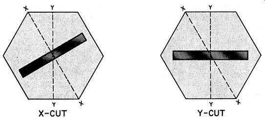
Fig. 12. Locations of X and Y cuts in a "mother" stone.
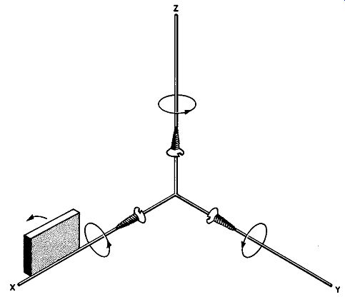
Fig. 13. Basic axes used in orientation specification, and positive rotation
directions.
19. The IRE System of Orientation Specification
Since the orientation of plates depends upon the manner and degree of rotation around the X, Y, and Z axes of the stone, it is necessary first to agree upon a method of describing whether the rotation is clockwise or counterclockwise around a given axis. First, note in Fig. 13 the three coordinate axes that are mutually perpendicular just like the axes in a quartz crystal. Starting from the origin of the coordinates are three wood screws that are to be pictured as being driven towards the ends of the axes in the usual manner, i.e., by turning the screwdriver clockwise as one faces in the direction of drive. The arrows show the direction of rotation for this condition.
If a quartz plate is now pictured as resting on edge, say on the X axis and is rotated as shown, its direction is that of the driven screw and, by convention, is said to rotate in a positive direction; if it moved opposite to the screw direction, the rotation is called negative. Exactly the same convention is adopted for the Y and Z axes so that specifying the axis of rotation and the number of degrees preceded by a plus or minus sign completely describes the character and extent of motion.
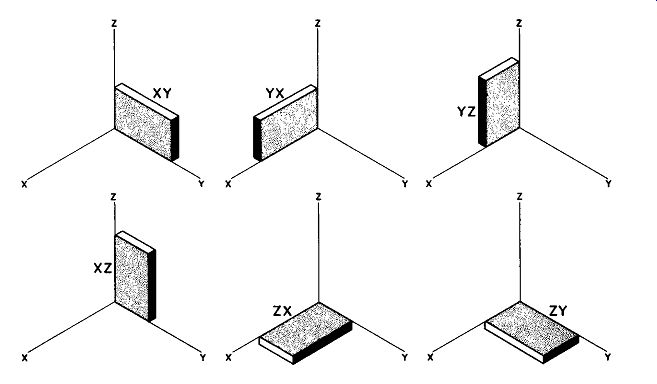
Fig. 14. Basic crystal locations before rotation, and their designations.
To specify the orientation of the cut, the crystal blank is assumed to have a hypothetical initial position, with one corner at the origin of the coordinate system, and the thickness, width, and length lying along the axes. There are six possible initial positions, each of which is described by two letters, the first letter indicating the thickness axis and the second letter the length axis. These positions are thus designated xy, xz, yx, yz, zx, and zy. Figs. 13 and 14 should make clear what is meant by each of these initial positions.
The blank shown in Fig. 13 has its thickness along the Y axis and its length along the X axis. Thus, this initial position is specified as yx. The reader should study each of the five positions in Fig. 14 to be certain that he understands the terminology.
In practice, the initial position is chosen so that the final orientation may be reached with a minimum number of rotations.
These rotations are taken about axes that parallel the dimensions of the crystal at the time of rotation and are designated by the letters t, w, and l standing for thickness, width, and length.
The examples given below illustrate the use of this system.
Example 1 (Fig. 15) : The geometrical specification of the rotation of the plate is given as yzw + 30 degrees. This means that the initial position is yz and that the blank is rotated 30 degrees in a positive direction around the w (or width axis).
Example 2 (Fig. 16) : The specification is xyt-30 degrees.
Thus, the blank lies with its length along the y axis, its thickness along the x axis, and is rotated opposite from the screw direction along the thickness axis 30 degrees. (Hence the minus sign before the angle specification.) Example 3 (Fig. 17) : This blank starts with its thickness axis along y and its length along x, with two sequential rotations needed for it to reach its final orientation. The first rotation occurs along its thickness axis, 10 degrees downward or -10 degrees. The second rotation takes place in a positive direction around the length axis over an angle o1 45 degrees ( +45 degrees) . The specification for its final position is then yxtl -10 degrees/+45 degrees.
Most crystal cuts are oriented by using a single rotation such as in Figs. 15 and 16; a few, however, require two and sometimes the maximum of three rotations.
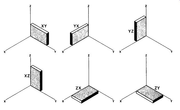
Fig. 15. Illustration of yzw + 30 degrees orientation.
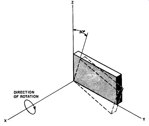
Fig. 16. Illustration of xyt - 30 degrees orientation.
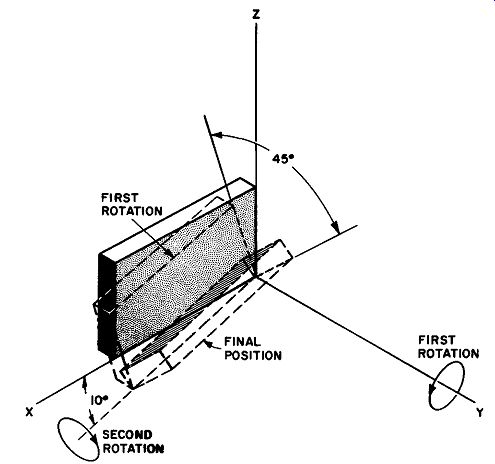
Fig. 17. Orientation of specified yxtl - 10 degrees/+ 45 degrees. Note that
two successive rotations are necessary: (1) along thickness axis downward 10
degrees, (2) along the length axis clockwise 45 degrees.
20. Popular Cut Orientations
Standard quartz elements are conventionally divided into two groups: (1) Rotated X-cut crystals and (2) rotated Y-cut crystals.
The X and Y cuts have their thickness dimensions parallel to the X and Y axes, respectively, with the length and width dimensions parallel to the remaining axes. Thus, in describing an orientation, the X cut is the equivalent of the two initial positions X)' and xz (see Fig. 14) and the Y cut is initially in the yx or yz position. Be longing to the X and Y groups, then, are those crystals whose rotation symbols begin with the letters x and y respectively. As a gen eral rule, the low-frequency units are cut from the X group and the medium to high-frequency blanks from the Y group. With one or two exceptions, Z-cut crystals (thickness parallel to Z-axis) are impractical.
In Table I, an attempt has been made to show the differences between popular cuts with respect to orientation, mode of vibration, customary frequency range, and range of temperature coefficients.
21. Thickness-Frequency Ratio (Frequency Factor)
For most crystal cuts, the frequency is determined chiefly by the thickness of the finished blank. Depending upon the orientation, the thickness for a given frequency varies considerably from cut to cut so that it is convenient to express the thickness-frequency characteristics of each orientation by a constant number derived from the equation: f = k/t where f frequency in me t = thickness in thousandths of an inch The equation indicates that frequency is inversely proportional to thickness so that k, the product off and t, is a large number for those crystals which are relatively thick even at high frequencies.
For example, the X cut has a frequency factor of 112.6 while an AT cut is rated at 66.4. Thus, for a given frequency of oscillation, the AT cut is one of the thinnest of blanks.
TABLE I DIFFERENCES BETWEEN POPULAR CRYSTAL CUTS
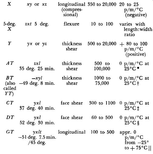

The AT-cut crystal may be oriented to give a zero temperature coefficient at any one of a number of different temperatures. The particular AT cut used here is one designed to provide ;rero coefficient at about room temperature.
t The BT cut does not have the ability to stay on frequency over as large a variation from room temperature as the AT cut.
:t: The CT cut has the same limitations as the BT cut.
§ The DT cut is especially useful for low frequency standards operating at room temperature.
JI Note the long range over which the temperature coefficient is virtually zero.
The frequency factors for the popular cuts are as follows:
X Cut .................... 112.6
Y Cut ....... . ........ ...... 77.0
AT Cut ............ ....... 66.4
BT Cut .................... 100
CT Cut................ 122
DT Cut............... 81
GT Cut .................... 131.t
• In the case of the CT cut, whose vibrational mode is face shear, l is the length or width rather than the thickness.
In longitudinal mode, width rather than thickness controls frequency.
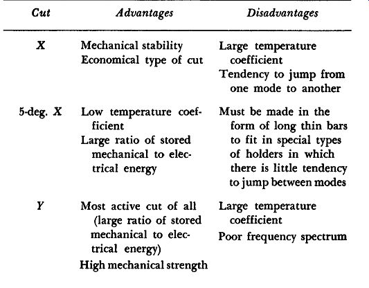
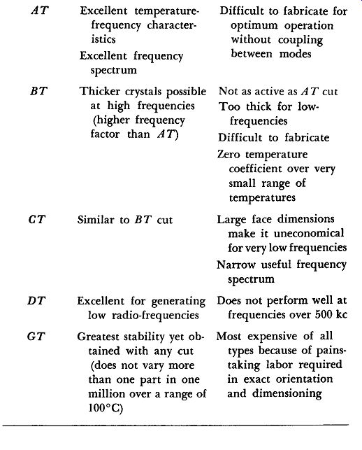
22. Summary of Advantages and Disadvantages of Various Cuts
The advantages and disadvantages of each of the types of cuts specified in Par. 20 are presented for convenience in Table 2.
TABLE 2
23. Mounts and Supports for Finished Crystals
In general, the requisites for a satisfactory crystal support include: (a) establishment of good electrical connection to the electrodes, (b) least possible damping or mechanical impedance acting on vibrating blank, (c) firm support of the crystal to protect against mechanical shock and vibration, and (d) adaptability for hermetic sealing.
Military Standard crystal holders currently recommended for use in equipment of new design include only two categories: pressure mounting and wire mounting. The first type involves a sup port in which the crystal is placed between two elements under pressure; the latter type consists of wire supports cemented directly to the crystal. In this review, these general classifications are further subdivided into smaller groups that differ from each other sufficiently to warrant separate illustration.
Pressure Sandwich. In holders of this type, the crystal is held between two flat electrodes under light spring pressure. In a commercial assembly, identical electrodes are, in turn, sandwiched between two contact plates that connect to two metal prongs. The prongs serve simultaneously as electrical contacts and plugs that fit into the holder socket (Fig. 18). A fiber washer, the pressure spring, and a neoprene gasket for hermetic sealing complete the assembly. When the cover is screwed down to the holder case, the unit may be used in any position. The advantages of pressure sandwiches include ruggedness and low cost; due to the spring pressure, however, a certain amount of mechanical impedance is added to the crystal so that crystals mounted in this type of holder exhibit less activity than in more critically designed mounts.
Air Gap Mounts. The holder shown in Fig. 18 may be changed to an air gap type by adding tiny glass spacers between the two electrodes so that the crystal rests on the lower one while the upper electrode is separated from the crystal by an air gap of about 3 mils in thickness. Unfortunately, this type of holder loses its ruggedness because the crystal is free to move about in the space between electrodes. Clamped Air Gap mounts do away with this difficulty by holding the crystal in place at the four corners while air gaps exist above and below the crystal over much of its area. For some crystal modes, instead of clamping at the corners, the crystal is held by small triangular "lands" near the center of the long edge (nodal clamping). Corner clamping is particularly effective with high frequency thickness-shear crystals, while nodal clamping is used mainly for low-frequency crystals that vibrate in a longitudinal mode.
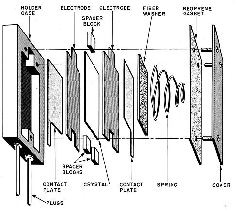
Fig. 18. Construction of "pressure-sandwich'' type of mount.
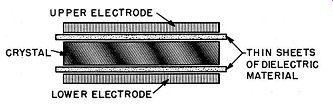
Fig. 19. "Dielectric sandwich" type of mount.
Dielectric Sandwich. One of the dangers involved in overdriving a crystal in either a pressure sandwich or air-gap mount is that of arcing between the electrodes and the quartz, an effect that may puncture the crystal or oxidize the electrodes so as to render the unit useless. Arcing is due to ionization of air between the blank and the electrodes; the problem this introduces may be minimized by inserting thin sheets of high dielectric material, such as mica, fused quartz, cellophane, rubber, etc., between the electrodes and the faces of the crystal (Fig. 19).
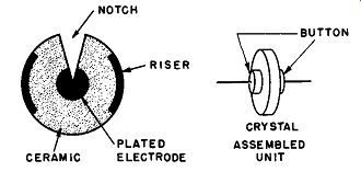
Fig. 20. Button type of mount.
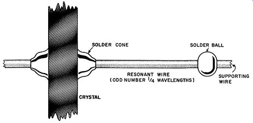
Fig. 21. Wire type of mount.
Button Mounts. The ceramic button crystal mount represents the ultimate thus far in crystal-holder design via the sandwich and air-gap evolutionary chain. The ceramic button electrodes are very thin metallic platings that cover a small circular area at the center of each ceramic plate. A tiny air gap, between three and five microns (thousandths of millimeters), is obtained by means of thin plated metal risers at the edges of the buttons. (See Figure 20.) A notch in each ceramic button permits an extension of the electrode plating on to the other side for contact with external leads. Button mounts have very low shunt capacitance, practically no spurious mode tendencies, and little damping and are quite rugged.
Plated Crystals. Thin films of gold or silver may be deposited on crystal faces by evaporating the metal in a vacuum and allowing it to condense on the exposed portions of the crystal; another technique coming into favor is a sputtering process in which crystals are subject to ionic bombardment from high voltage negative electrodes of the desired metal, the process again being carried on in a vacuum. Silver and gold are favored because of the strength of the solder bonds possible with these metals, their resistance to corrosion, and the ease with which they are handled. Other metals used in special cases are nickel, copper, and aluminum, the last being preferred where a very light weight element is required. Plated electrodes have many advantages: they provide maximum piezo electric coupling, possibility of arcing between crystal and electrodes is reduced, there is no possibility of crystal shifting between electrodes, frictional losses between crystal and electrodes are removed, and the plating protects the crystal from erosion.
Plated crystals may be supported between pressure pins or pressure knife edges for nodal or edge clamping.
Wire Mounting. One of the chief disadvantages of any type of pressure mount is the damping effect caused by the electrodes or contact plates, yet the fact that pressure is present brings about a desirable condition-that of reasonable immunity to shock and vibration. Wire mounting makes it possible to retain the advantages of shock-proof design while, at the same time, reducing the effects of damping to a minimum.
By mounting the crystal as shown in Fig. 21, the wire lengths indicated may be so "tuned" as to become mechanically resonant to the crystal frequency; under these conditions, the wires vibrate with the blank and return mechanical energy to the system, reducing the impedance to a very low figure.
In the fabrication process, the crystal is first given a pair of small silver footings to which the wires are later to be attached; these footings are only 40 to 90 mils in diameter. The electrodes are then plated on the crystal by evaporation or sputtering with silver (or sometimes gold, if corrosion resistance is important enough to warrant it). The mounting wires are phosphor-bronze, a material of high tensile strength and comparative immunity to metal "fatigue." They are soldered to the footings and the solder spot is formed into a cone as shown in the figure. The mechanically resonant length of wire is then determined and a ball of solder, which (by virtue of its mass) serves as the terminus of the free resonant length of wire, is then soldered to the lead. The solder ball behaves as a clamped point, which reflects the wave energy back
to the crystal, and is placed at an odd quarter-wavelength from the peak of the solder cone. The supporting wires are then carefully bent to form springs and secured to the crystal holder prongs.
24. Crystal Ovens
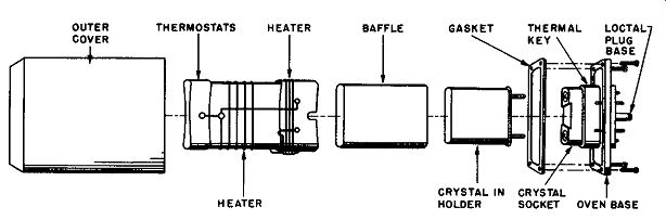
Fig. 22. Typical compact crystal oven which plugs into a loctal socket.
Excellent as the temperature characteristics of the "-T"-cut crystals may be, the rigorous frequency stability requirements in both commercial and military radio installations demand temperature control in many instances.
Small crystal ovens, occupying not much more volume than a good-sized receiving tube, are now almost universally depended upon to maintain constant frequency in all but broadcast station installations. Figure 22 is an exploded view of a small crystal oven equivalent to Military Type HD-54/U and, although it is not de signed for precision control, it does offer improved stability for crystal controlled devices, especially those that undergo rapid extremes of temperature as found, for example, in aircraft.
The thermal key, shown as a part of the base assembly, is a metallic heat-distributing layer that makes close thermal contact with the base of the distributing shell around which the heaters are wound. The baffle is a plastic cover that forms the walls of the crystal chamber. Its purpose is to form a heat-storing as well as a heat-insulating layer between the heater distributing shell and the crystal unit. Two thermostats and two heaters are provided.
One thermostat-heater combination is for quick oven warmup when the oven is first turned on. This thermostat is adjusted to open its associated heater circuit at a temperature just below the desired operating temperature while the second pair determines the operating characteristics. The outer cover, a plastic compos1t10n, is large enough to provide a small air chamber around the crystal compartment.
The crystal oven illustrated in Fig. 22 is designed to plug into a regular 8-pin !octal type of tube socket. Over an ambient temperature range from -55°C to +55°C it will maintain a maximum deviation within the range from -7° to +6° around its normal operating temperature of 75°C. It measures 1.9 inches in height, 1.4 inches in length, and 1.0 inch in width and weighs only 2 ounces.
25. QUIZ
1. Define the temperature coefficient as it pertains to crystals.
2. A Y-cut crystal is ground to operate at 3 me at 20°C. Its temperature co efficient is listed as +60 p/m/°C. Calculate the operational frequency of the crystal if the temperature rises to 25°C.
3. Explain the IRE system of crystal orientation, developing at least two illustrations to explain your discussion.
4. Draw a diagram orienting the initial position of the crystal when given these specifications: xy, yx, yz, xz, zx, and zy.
5. What specification would the technician normally require in differentiating between the various crystal cuts?
6. List six different types of crystal cuts. Specify which of these are most commonly used in design applications.
7. Explain the term "frequency factor'" and give the mathematical equation defining it.
8. Summarize the advantages and disadvantages of the following crystal cuts: x, y, AT, GT.
9. Differentiate between the pressure mounting and wire mounting types of crystal holders.
10. What is the function of a crystal oven?