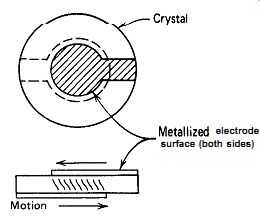
Figure 2.1. Shear motion of an AT cut crystal at fundamental resonance.
| Home | Audio mag. | Stereo Review mag. | High Fidelity mag. | AE/AA mag. |
This section covers the electrical characteristics of quartz crystals from a circuit design standpoint. For information on their mechanical characteristics or on the manufacturing process, the reader is referred to any standard text on quartz crystals.
Quartz exhibits a piezoelectric effect, that is, applying a voltage to the opposing surfaces of a piece of properly oriented quartz will make it change shape mechanically (and vice versa). A quartz crystal is a small, thin piece of quartz with two opposite surfaces metallized to make electrical connections. Its physical dimensions are tightly controlled since they control oscillation frequency.
Although there are many crystal cuts, at high frequencies (1 MHz and above), the one most commonly used is the AT cut. An AT-cut crystal is a thin piece of quartz with two parallel or slightly convex surfaces, usually about the size of a nickel or less. Electrical connections are made to the crystal by metalizing the two parallel faces on opposite sides of the crystal. The crystal's resonant frequency is inversely proportional to the crystal's thickness between these two metallized surfaces. Applying a voltage between the two metallized surfaces causes the AT crystal to move sideways internally in a thickness shear movement, as shown in Fig. 2.1. The traditional equivalent circuit using lumped constant elements for the crystal is shown in Fig. 2.2. Inductance L, and series capacitance C, represent the crystal's frequency-sensitive elements.
Capacitance C, is the capacitance between the two metallized surfaces used as electrode contacts on the crystal and runs about 3-15 pF for most crystals.
The series resistance R, of a typical crystal of any type of cut varies from about 10 R, at 20 MHz, to a few hundred ohms at 1 MHz, up to a few thousand ohms at 100 kHz, and up to 200,000 a at 1 kHz.
Metallized electrode surface (both sides)
Figure 2.1. Shear motion of an AT
cut crystal at fundamental resonance.
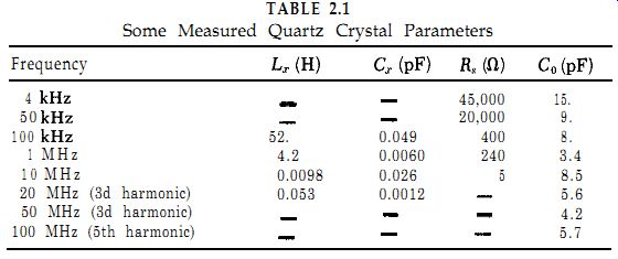
Table 2.1 shows some measured values of L,, C,, Co, and R, for several crystals.
The lowest fundamental frequency available in a quartz crystal is about 1 kHz. The highest fundamental frequency is about 20-25 MHz, above which the crystal becomes too thin and delicate to be handled.
Oscillation can be continued to about 200 MHz by operating the crystal on its third, fifth, seventh, or ninth harmonic. A crystal's series resistance increases with the harmonic, from about 40 R at 20 MHz to about 200 R at 200 MHz.
Figure 2.3 shows the maximum series resistance of quartz crystals over a frequency range of 1 kHz-200 MHz. These data are taken from several specifications, so more than one limit is shown at some frequencies. A typical crystal will have about two-thirds the maximum resistance specified in Fig. 2.3. This wide variation in series resistance from 10 to 200,000 R is the largest single factor in oscillator design and dominates the design of every oscillator circuit.
Figure 2.4 shows the maximum drive power that can be put into a crystal without excessive heating and frequency shift in the crystal, Figure 2.5 shows the maximum permissible drive voltage across the crystal at exact series resonance. Figure 2.5 is derived from the series resistance and maximum power data given in Figs. 2.3 and 2.4. Figures 2.3-2.5 apply to crystals of all common types of cuts mounted in a gas-filled container.
Note that in Fig. 2.5 the maximum crystal voltage falls off rapidly above 1 MHz. This maximum voltage curve is a useful design tool.
Capacitance between metallized electrodes
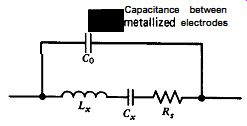
Figure 2.2. Equivalent circuit for a quartz crystal near fundamental resonance.
TABLE 2.1
Some Measured Quartz Crystal Parameters
Since crystals frequently operate slightly off resonance, measuring the voltage across the crystal is meaningless as a measure of current through the crystal. The practical solution is to measure the current through the crystal by means of the voltage drop across a series element and calculate the crystal's power dissipation by Z2R,, where Z is the current through the crystal and R, is the crystal's internal series resistance.
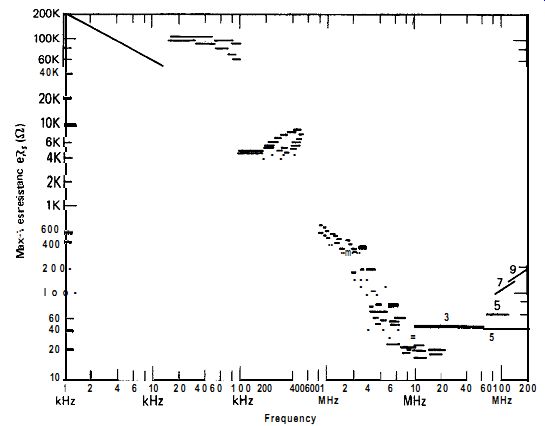
Figure 2.3. Maximum crystal series resistance R, as a function of frequency.
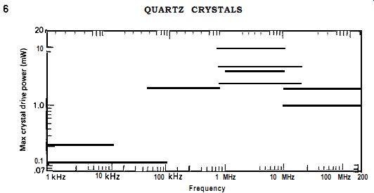
Figure 2.4. Maximum crystal power dissipation as a function of frequency.
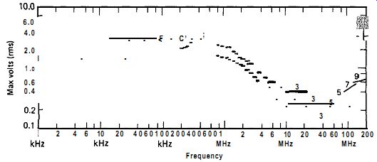
Figure 2.5. Maximum crystal-drive voltage at series resonance as a function
of frequency.
At frequencies above about 2 MHz, the AC voltage swing from an oscillator circuit operating from a 5V power supply can be higher than what should be put across the crystal at series resonance. An amplitude-limiting scheme is frequently needed to take care of this problem.
There is no difference in the construction of a series-resonant crystal and a parallel-resonant crystal, which are manufactured exactly alike.
The only difference between them is that the series-resonant frequency of the parallel-resonant crystal is set 100 ppm or so lower than the desired operating frequency. Parallel resonance means that a small capacitance of 32 pF or so should be placed across crystal terminals to obtain the desired operating frequency. This presumes that the external load across the crystal's terminals has a high impedance. If the external load across the crystal's terminals has a low impedance, then parallel resonance means that a small capacitance of 32 pF or so should be placed in series with the crystal and its low-impedance load to obtain the desired operating frequency.
Putting an external capacitor in series with the crystal's internal motional capacitance C, reduces the net total series capacitance of the two and thereby raises the crystal's series-resonant frequency. In practice, specifying parallel resonance simply tells the manufacturer to, set the crystal's series resonance a little lower than the frequency requested by the user, so that when the crystal is put in series with (or parallel with) a small capacitor, the crystal's resonant frequency will be what the user wants.
The AT cut offers a lot of advantages over other crystal cuts and has been brought to a high state of perfection. Warner and others at Bell Telephone Laboratories developed two outstanding AT crystal designs at 2.5 and 5 MHz for use in high-performance frequency standards. Both operate on the fifth harmonic. The 2.5-MHz crystal uses a large quartz blank 30 mm in diameter. Several papers published by the group at Bell Labs on crystal designs and the oscillator circuits used with them are listed in the reference and bibliography sections in this guide.
Among many items of interest, Warner and Bornmel et al. reported the following on AT crystals:
1.
2.
3.
4.
5.
Crystals operate differently in a vacuum than in air.
The series resistance of a crystal is 3 times lower in vacuum than in air, with a corresponding improvement in Q.
Above 30 MHz, there is no measurable difference in Q between operations in air or vacuum.
The maximum attainable crystal Q is an inverse function of frequency. It is also a function of the diameter and surface curvature of the crystal blank.
Harmonic operation gives improved Q when the crystal is operated in air. In a vacuum, the crystal's Q is the same for either fundamental or harmonic operation.
A glass container for the crystal gives less long-term frequency drift than a metal container.
The internal series resistance of the large high-Q 2.5-MHz crystal was 65 ohm. Since this varies as the cube of the harmonic, the crystal's internal resistance would be 1/27 of 65 or 2.4 ohm, if it were operated in a fundamental mode at 2.5 MHz. A value of 2.4 R is too low a load resistance for a transistor amplifier stage to drive easily. Warner points out that this is one of the main reasons for operating a high-Q crystal at a harmonic frequency-the crystal's internal series resistance is higher and much easier for a transistor amplifier stage to drive.
If we want to electrically pull a crystal off frequency with a variable capacitance diode or other means, it should be done at the crystal's fundamental frequency. The crystal will be much harder to pull off frequency and will not pull so far (percentagewise) when operated at a harmonic frequency, because of the crystal's greater phase shift with a given change in frequency.