Infrared Intruder Alarm
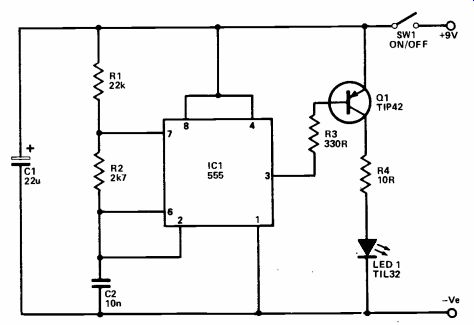
This alarm sounds when an invisible beam of infra -red light is bro ken by the intruder. The circuit is intended to feed an existing burglar alarm system. The system is very simple, and requires no special lenses or filters for operation over distances of about 2 meters or less. A short range is usually sufficient to cover en trances to rooms, span corridors, etc.
The unit consists of two separate circuits, one to produce an infra -red beam, and the other to detect it and sound the alarm if there is a break in the signal. In common with most systems of this type, a pulsed infrared beam is used. A modulated beam can easily be differentiated from the ambient infrared radiation, enabling a low power beam to be employed.
The transmitter is based on the popular 555 timer IC and it is used in the standard astable mode. R1, R2, and C2 are the timing components and these give an operating frequency of roughly 5k25Hz. A standard 555 oscillator does not produce a true squarewave out put, as the output is in the high state for a longer period than it is in the low state due to the fact that the output goes high during the time that C2 charges up through the relatively high resistance of R1 plus R2 and low while C2 discharges through the low resistance of R2 and an internal transistor of IC1. The values used in this case give an output which is in the low state for only about 10% of the time.
During these brief negative out put excursions Q1 is pulsed on by the base current it receives via R3. It then passes a current of about 500mA, to infrared LED1 by way of current limiting resistor R4. Of course, the average current through LED1 is only about 50 mA and this system therefore gives fairly strong pulses of infrared together with a reasonably low aver age current drain. There is no out put from LED1 in the visible light spectrum.
At the receiver the pulses of infrared are detected by photo-diode LED1. This is fed from the supply rails via load resistor R1.
The pulses of infrared cause the leakage current through LED1 to increase momentarily, giving a series of small voltage pulses at the junction of R1 and LED1. These are fed by C2 to the input of a straight forward high gain amplifier which uses Q1 and Q2 in a conventional two stage direct coupled arrangement. C2 and C4 are purposely given low values so that the circuit has a poor response at low frequencies. This gives good rejection of 50 Hertz signals produced by LED1 picking up the infra red radiation from mains powered lighting. The circuit has high gain at the much higher operating frequency of the transmitter circuit, though.
The output from the amplifier is coupled by C5 to a rectifier and smoothing circuit which utilizes D1, D2, C6, and R6. The positive bias produced by this circuit is fed to one input of operational amplifier IC1. The other input is fed with a bias voltage by R7 and R8. Normally the fixed bias to the inverting input will be higher than the bias fed to the non-inverting input.
IC1 is used as a comparator, and under these conditions its output goes high, energizing the relay coil with discrete buffer stage Q3 being used to provide the fairly high drive current required. If an intruder breaks the beam momentarily, the charge on C6 rapidly de cays, taking the non -inverting in put of IC1 below the inverting input. IC1's output then goes low, the relay is switched off, contacts RLA1 open and the main alarm system is triggered.
++++++++++++++++
Low Battery Voltage Indicator
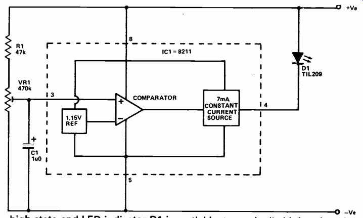
This circuit can be used to monitor a supply voltage of between about 5 and 25 volts (30V absolute maximum ) and will switch on a warning light if the supply falls below some predetermined threshold level.
The circuit is actually quite sophisticated, giving good reliability and precision. This is due to the use of an 8112 voltage detector IC.
A comparator forms the heart of the device, and a highly stable internally generated reference voltage is fed to the inverting in put of the comparator. Its non-inverting input is available at pin 3, and in this circuit it is fed from the supply lines via the potential divider circuit which consists of R1 and VR1. The output of the comparator is available at pin 4, by way of a constant current genera tor which limits the output current to a nominal figure of 7 mA.
If the voltage at the non-inverting input exceeds the reference voltage, the output assumes the high state and LED indicator D1 is not switched on. If the non-inverting input voltage falls below the reference level, the output then goes low and power is applied to D1. The constant current source limits the LED current to a suitable level. In practice VR1 is adjusted so that with the supply voltage at its minimum acceptable level the non -inverting input is at a potential just marginally higher than the reference voltage. A fall in supply voltage below the threshold level then takes the non -inverting input below the reference voltage and switches on the warning light. C1 decouples any stray pick-up which could otherwise cause spurious triggering of the circuit. The quiescent current consumption is typically about 50 uA.
++++++++++++++++++
Two Tone Alarm
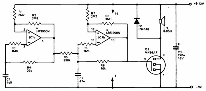
This circuit generates a penetrating two tone alarm signal having an output power of between about 250mW and 4W rms depending on the speaker impedance and supply voltage used.
The circuit is based on two of the four Norton amplifiers contained in the LM3900N IC. A Norton amplifier is in many ways similar to an ordinary operational amplifier, but it is the comparative input currents rather than the in put voltages that determine the output voltage. IC1b is used in a type of relaxation oscillator which generates the audio tone. Initially the bias current flowing into the non -inverting input takes the out put high, and C2 begins to charge via R9. This causes the current flowing into the inverting input through R6 to gradually increase as the voltage on C2 builds up, until it exceeds the non -inverting input bias current. The output of IC1b then goes low, causing C2 to discharge through R9 until the inverting input current becomes less than that flowing into the non-inverting input. IC1b output then goes high, and the procedure starts again from the beginning.
Note that when IC1b output went from the high to the low state, this resulted in R8 draining off some of the non -inverting input bias cur rent where it had previously added to it. This makes it necessary for C2 to discharge consider ably before the current into the inverting input drops below that applied to the non -inverting input.
This effect is a form of "hysteresis", and is essential to the operation of the circuit. R8 also provides positive feedback which ensures that once IC1b output starts to change polarity, it rapidly and reIiably switches from one state to the other.
The squarewave output of IC1b is at quite a high impedance, and so the loudspeaker is driven by way of a common source amplifier using VMOS transistor Q1. IC1a is used in a second oscillator circuit, but this has component values which give oscillation at a frequency of only a few Hertz. Its out put is loosely coupled to C2 by R5, and it frequency modulates the tone generator to produce a sort of warbling effect. This gives a much more noticeable and less easily masked signal than a straight forward audio tone.
+++++++++++++++++
LED Flasher
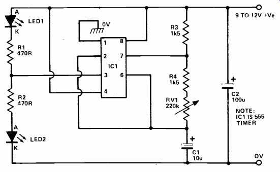
This circuit can be used to either pulse a single LED on and off repetitively or to similarly drive a pair of LEDs in anti -phase, so that one LED turns off when the other turns on, and vice versa. In either case, the flashing rate of each LED is variable from about 15 flashes per minute to 2,000 flashes per minute via a small pre-set pot.
The circuit can be used to add visual interest to a variety of toys, gadgets, and instruments. Model railway enthusiasts can use the unit to simulate flashing lights on miniature police cars and ambulances, etc, or to simulate warning beacons on Zebra crossings.
IC1 is a type 555 'timer' IC, and is connected as a free -running or as table multivibrator that produces a square -wave output signal at pin
3. When this output signal is high it cuts LED 1 off and drives LED 2 on, and when it is low it pulls LED 1 on and cuts LED 2 off; the two LEDs thus turn on and off in anti-phase.
The operating frequency of IC1, and thus the flashing rate of the LEDs, is determined by the values of C1 and R4-RV1: the flashing rate is variable between roughly 15 and 2,000 flashes or cycles per minute via RV1. The ON currents of the LEDs are limited to safe values by the R1 and R2 470R limiting resistors.
The flashing rate can be carried via RV1. If you want the circuit to operate with only one flashing LED, you can either short out the unwanted LED or remove it and it's associated 470R resistor from the circuit.
++++++++++++++++
Light Change Detector
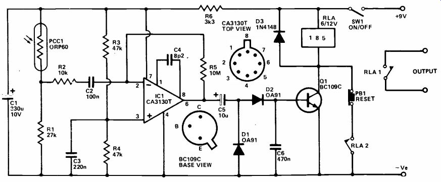
This simple light activated switch can be employed in intruder alarm systems or in certain other applications where a proximity detector is required. It is not a light operated switch of the type which responds to some particular ambient light level but instead it res ponds to rapid changes in light level. It will for example, trigger if a torch is shone on or near the photocell or if someone passing in front of the unit casts a shadow onto the photocell. The unit is unaffected by natural, slow changes in light level.
The photocell used in the unit is cadmium sulphide photoresistor, PCC1, and together with R1 this forms a potential divider connected across the supply lines. The voltage at the junction of R1 and PCC1 depends upon the resistance of PCC1, which in turn depends upon the light level.
IC1 is an operational amplifier used in the inverting mode. R2 and R5 form a negative feedback network which set the voltage gain of the circuit; high gain is required in order to give the unit good sensitivity.
The output from PCC1 and R1 is coupled to the input of the amplifier, but C2 provides DC blocking so that the DC output from these components is of no consequence. However, rapid changes in the output voltage from the photocell circuit will be passed to the input of the amplifier and will appear at the output.
The output from IC1 is coupled by C5 to a smoothing and rectifier circuit consisting of D1, D2, and C6. When the unit is activated, the positive bias produced across C6 is sufficient to bias Q1 into conduction so that it energizes the relay coil which forms its collector load. RLA2 then closes and maintains the supply to the relay coil, so that the circuit latches on. The alarm or other controlled equipment is operated by RLA1.
SW2 can be used to break the supply to the relay and thus reset the circuit. SW1 is the on/off switch; C4 is the compensation capacitor for IC1 and D3 is the normal protective diode.
++++++++++++++
Opto-Thermo Alarm
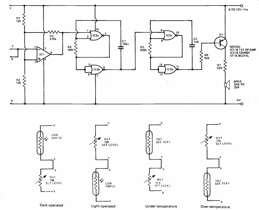
This useful project can be powered from a 9V to 12V supply, and produces a pulsed -tone alarm signal in a small speaker when light or temperature levels go be yond pre-set limits. The unit can be made to activate either when these levels go above or fall below pre-set values, depending on the manner in which the input sensors (an LDR or light -dependent resistor for 'light' operation, or a thermistor for 'temperature' operation) are connected to the unit.
The unit has a variety of uses in the house and in the car. In the car, it can be used to give a warning of road ice or of engine or gearbox overheating. In the home, it can be used to give a warning of a burnt-out night -light or a failed heating system in a child's room, or it can be used as a 'dawn' alarm.
IC1 is a type 741 operational amplifier wired as a voltage comparator with a small amount of regenerative feedback. A fixed 'half supply' reference voltage is fed to input pin 3 of the op -amp via R1 and R2, and a variable voltage is fed to pin 2 via RV1 and the LDR or thermistor. The output of IC1 is used to activate (turn on or off) a 'slow' gated astable multivibrator formed by IC2a and IC2b, and the output of IC2b is used to activate a 'fast' gated astable formed by IC2c and IC2d which has its output fed to the speaker via Q1.
When the pin 2 voltage of IC1 is below that of pin 3, the output of IC1 is high, and the two astables are gated off and no output is produced from the unit. When the pin 2 voltage of IC1 is above that of pin 3, the output of IC1 is low, so slow astable IC2a-IC2b is gated on and its output alternately switches the fast IC2c-IC2d astable on and off to produce a pulsed-tone in the speaker.
Connect the input sensor (either an LDR or a thermistor) and RV1 to the inputs of the unit to obtain the desired types of operation. For light operation, the LDR must pre sent a resistance in the range 900R to 9kR at the desired trigger level: an ORP12 is suitable for use in most cases. For temperature operation, the thermistor must be a negative -temperature-coefficient (NTC) type that presents a resistance in the range 900R to 9kR at the desired trigger level: a VA1066S is suitable for use in most cases. The speaker can have any impedance in the range 3R to 25R, the latter value being preferred.
The unit can be powered from any DC supply in the 9V to 12V range. In use RV1 is simply adjusted so that the alarm just activates at the desired light or temperature level. The unit produces an attractive pulsed -tone signal when it is activated.
++++++
Car Battery Alarm
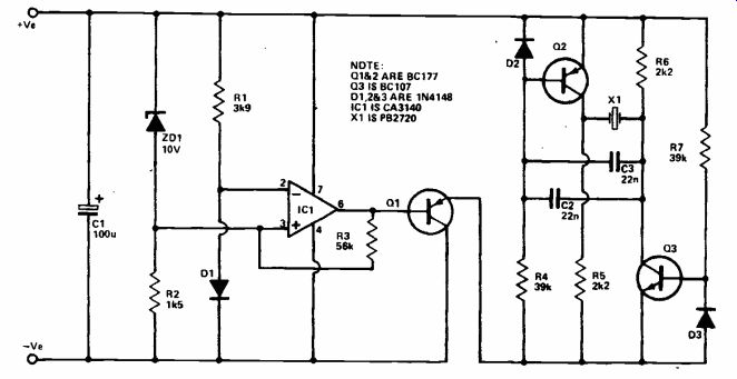
This circuit is intended for use with a 12V car or boat battery and sounds an alarm if the battery voltage drops below about 10y.
An audible alarm is used in preference to the more usual indicator light because an audible signal is far less likely to be missed.
IC1 and its associated circuitry form a voltage detector circuit; IC1 is used here as a voltage comparator rather than an operational amplifier. R1 and D1 provide a stabilized potential of about OV7 to the inverting input of IC1. The voltage supplied to the non -inverting in put is equal to the supply voltage minus the nominal 10V dropped through zener diode ZD1. Thus the potential at the non -inverting in put will normally be about 2V or more and since this is higher than the voltage fed to the other input the output assumes the high state.
Therefore 01, an emitter follower buffer stage, becomes cut off and no power is fed to the audio alarm circuit at its output.
If the supply voltage falls below about 10V7, then the voltage fed to the non-inverting input falls be low the reference level at the other input and IC1's output goes low.
Q1 is then switched on and power is connected to the alarm circuit fed from its output. Due to imperfections in the performance of practical zener diodes, the actual voltage at which the alarm is triggered is a little lower than the theoretical one and is typically a fraction over 10V (or 11V if preferred, by using an 11V component in the ZD1 position). R3 is Q3 used to introduce a small amount of positive feedback which ensures that the unit switches cleanly from one state to the other and prevents erratic operation.
The alarm generator circuit uses Q2 and Q3 as an astable multivibrator and these drive ceramic resonator X1 with the anti -phase signals at their collectors. This gives the necessary large voltage swing to X1 and produces a reasonably loud output at about 2kHz or so.
+++++++++++++++++
Water Alarm
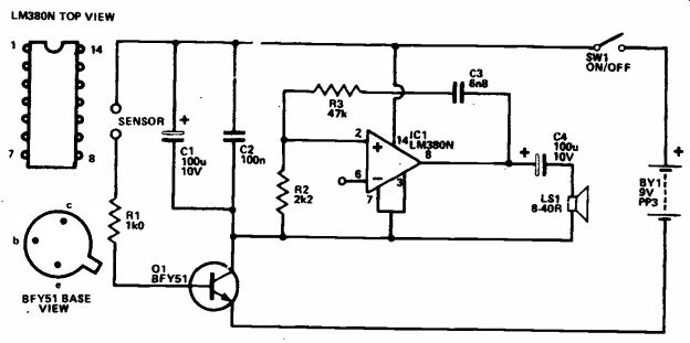
This simple water detector circuit can be used in such applications as a rain alarm, cistern overflow alarm, or just to indicate when the water in a bath has reached the required depth.
The circuit consists of two sections; an electronic switch and an audio alarm generator: Q1 is used as the switch and under normal conditions it is cut off, supplying no significant current to the alarm generator circuit which forms its collector load. The sensor in 01's base circuit merely consists of two pieces of metal insulated from one another, arranged so that when the rain, bath water, or whatever touches the sensor, it bridges the two pieces of metal. Although pure water is a very poor conductor of electricity, tap water is likely to contain amounts of impurities which will be sufficient to make the water conduct reasonably well. Thus when water is detected by the sensor, its resistance falls to a relatively low level (typically a few kilohms), biasing Q1 hard into conduction. Virtually the full supply voltage is then supplied to the alarm circuit, and the alarm sounds. R1 is a current limiting resistor which prevents Q1 from passing an excessive base current if a short circuit or very low impedance should appear across the sensor terminals.
An L.M380N audio power amplifier device (IC1) is used to generate the audio alarm signal. It is made to oscillate by using C3, R3, and R2 to give frequency selective positive feedback between the output and non-inverting input.
The circuit oscillates at approximately 600 Hz, and provides an output of a few hundred milliwatts to a miniature loudspeaker. This gives a reasonably loud and penetrating sound.
Under quiescent conditions the circuit consumes less than one micro-amp, and so even with continuous use the battery will have virtually its shelf life. With the alarm sounding, the current consumption increases to about 30 to 100mA, (depending on the speaker impedance). Note that C2 should be mounted physically close to IC1.
A little ingenuity must be used when making the sensor. In most applications a small piece of stripboard will be all that is needed.
++++++++++
Low-Power LED Flasher
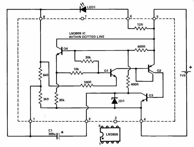
National Semiconductor have produced an integrated circuit to be used specifically for flashing an LED, even at voltages as low as 1V1, with an average current consumption orders of magnitude be low that of an LED on its own.
The circuit achieves it's very low current consumption because the LED is only illuminated 1% of the time, and only Q4 is turned on for the rest of the time--drawing a current of only 50uA while on. The 300u capacitor determines the flash rate by charging up via the two internal 400R resistors and the 3k resistor. Q1 and Q2 are turned off until the voltage at the positive end of C1 reaches about 1V; the exact voltage is determined by the junction voltage drop of Q1 and Q4 plus the voltage divider across Q4's base and emitter.
When the voltage at pin 1 is 1V more negative than the positive supply (pin 5), Q1 starts to turn on.
This in turn switches on Q2 and Q3. Q3 is a medium-power transistor that can handle 100mA and rapidly brings pin 2 close to zero supplies a high current pulse to the LED, limited by the 12R resistor between pins 5 and 6. The cycle then repeats itself.
(adapted from: Electronics Digest (Vol. 2 No. 3--WINTER 1981))
NEXT: Switches