12.1 THE D'ARSONVAL METER
The D'Arsonval meter consists of a moving coil of fine wire suspended between the poles of a permanent magnet, and has long been the most popular analog measuring instrument. The taut-band meter, a recent improvement, replaces the jeweled pivot with a torsion band suspension to eliminate hysteresis (stickiness) in the movement of the pointer. Precision meters have mirrored scales to eliminate parallax, the error incurred when the eye views the meter from a side angle.
Keeping the mirror image of the pointer directly behind the pointer ensures that you are viewing the meter "head-on." D'Arsonval meters are specified in terms of their full-scale current sensitivity and their coil resistance. Sensitive D'Arsonval meters (often called galvanometers) can be used to produce a voltmeter, ammeter, or ohmmeter of any desired range using the Ohm's law calculations outlined in the next three sections.
The resistance of an unknown meter should not be determined by measuring it with an ohmmeter because a VOM may inject enough current to destroy a sensitive meter. Instead, bleed full-scale current though the meter and a high-value resistor (100 k-Ohm- 10 k-Ohm), measure the voltage across the meter coil and calculate Rc = Vc/I, as illustrated in Fig. 12-1.
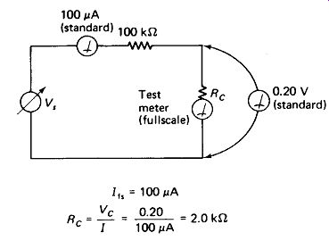
FIGURE 12-1 Circuit for determining the full-scale current and coil resistance
of a meter without damaging It.
12.2 THE VOLTMETER CIRCUIT
A voltmeter circuit is shown in Fig. 12-2(a). A multiplying resistor, Rm, is placed in series with the meter to drop all the input voltage except that required by the meter itself. To calculate the value of the multiplying resistor:
. Calculate the full-scale voltage drop across the meter itself: Ve
= I t, Rc.
Select the full-scale voltage input, Vin
. . Subtract to find the voltage on the resistor: VRm = - Vc.
. Calculate Rm using the full-scale meter current: Rm
= VRm/I, s
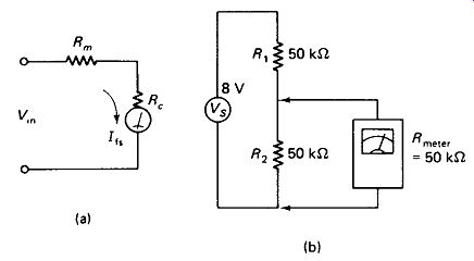
FIGURE 12-2 (a) The basic voltmeter circuit consists of a multiplying resistance
R m in series with the meter movement, (b) If the total meter resistance Rm
+ Rc Is not many times greater than the circuit Thevenin resistance R, || R
connecting the meter will seriously load down the voltage being measured.
EXAMPLE 12-1
A meter with /f,= 100 /iA and Rc = 2 k-Ohm is to be used to make a 5-V full-scale metering circuit. Find Rm.
Solution
=48 kOhm
Voltmeter Loading is an undesirable effect produced when the meter circuit siphons away an appreciable portion of the current from the circuit under test. The result is an actual lowering of the voltage between the test points when the meter is connected. The extent of voltmeter loading can be calculated by Ohm, s law if the meter resistance and circuit resistances are known.
EXAMPLE 12-2
Find the error that will be encountered if the meter of Example 12-1 is used to measure in the circuit of Fig. 12-2(b).
Solution The voltage before the meter is connected is 0.5 X 8 V, or 4 V, by inspection. The meter circuit resistance totals 50 kOhm (Rc + Rm).
=33%
Voltmeter loading error can be held to a maximum of 10% if the meter has a resistance at least 10 times the lower of or R2 in Fig. 12-2(b), to 1% if is 100 times or R2, and 0.1% if R_meter is 1000 times R1 or R2.
Voltmeter Resistance is, therefore, an important property with which the technician should be familiar. Electronic meters (VTVMs, DVMs, and FET meters) generally have input resistances of about 10 Ml. The standard oscilloscope input impedance is 1 Ml, or 10 Ml when used with a X 10 probe. The common portable VOM has an input sensitivity of 20 k Ohm/V, which means that it has a resistance of 200 k Ohm on the 10-V scale, 2 M-ohm on the 100-V scale, 5 M-ohm R on the 250-V scale, and so on.
Many instruments also have an appreciable capacitance in shunt with their input resistance, and this adds to the loading effect at high frequencies. For example, a 'scope with 20 pF of input capacitance measuring a 1 MHz signal presents an input impedance of about 8 kohm capacitive, and its loading effect must be reckoned with this in mind.
If two metering devices are available (e.g., a VOM and an oscilloscope), the loading effect of one can actually be observed on the other as they are alternately connected and disconnected to the points under test. This technique is often more practical than trying to calculate the relative impedances of the circuit versus the meter.
12.3 AMMETER CIRCUITS
A galvanometer is converted to an ammeter of any desired range by connecting a shunt resistor across it which bypasses all the measured current except that required by the meter itself. The circuit is shown in Fig. 12-3(a). To calculate the value of the shunt:
. Calculate the full scale voltage across the meter: V_ts = I tsRc-
. Select the full-scale input current I_in.
. Subtract the meter’s full-scale current to find the current that must be carried by the shunt resistor: IRsb
= / m
- / fs.
. Calculate Rsh using the full-scale voltage which appears across the meter and shunt resistor together: Rsh = VfJIRsh.
EXAMPLE 12-3
A 0 to 1-mA meter movement with a coil resistance of 50 is to be converted to a 0 to 15-mA meter. Find the required shunt resistance.
Solution
= 3.57 ohm
Ammeter Loading: Notice that this metering circuit has a resistance of 50 || 3.57, or 3.33 Q, which must be considered when the meter is inserted in a line. This resistance will cause a line-voltage drop of 50 mV at full-scale current. Generally, these facts will present no serious problem, but in some cases meter voltage Vfs may be an appreciable fraction of the source voltage Vs, or changes in the load current may produce objectionable output voltage changes due to the IR drop across the meter. Both of these ammeter loading problems are represented in extreme degree by Fig. 12-3(b). The meter here is 150 mA with a 3.3-K coil.
Multiple-Range Ammeters can be constructed by simply switching in different shunt resistors, as shown in Fig. 12-3(c). If this circuit is used, however, it is essential that a make-before-break (also called shorting) type of switch be used.
Otherwise, the entire input current would flow through the sensitive meter coil while the switch wiper was in transition between positions, and a bent meter pointer or burned-out coil would be the likely result.
If such a switch is not available, an Ayrton shunt arrangement, shown in Fig. 12-3(d) can be used. Note that the measured current is interrupted during switch transitions with the Ayrton shunt. This may be objectionable in some applications, such as those involving inductive loads.
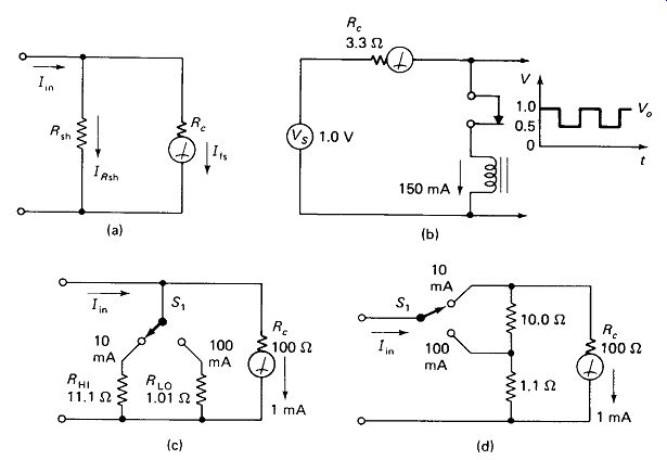
FIGURE 12-3 (a) Basic ammeter circuit, (b) Ammeter voltage drop or loading. (c)
Multirange ammeter, (d) Ayrton shunt to prevent overloading the ammeter during
switching.
12.4 OHMMETER CIRCUITS
A series ohmmeter circuit is shown in Fig. 12-4(a). In operation the probe lines are first shorted together, and zeroing resistance Rt is adjusted for full-scale meter deflection. Then the unknown resistor is connected and its value is read from a specially calibrated scale.
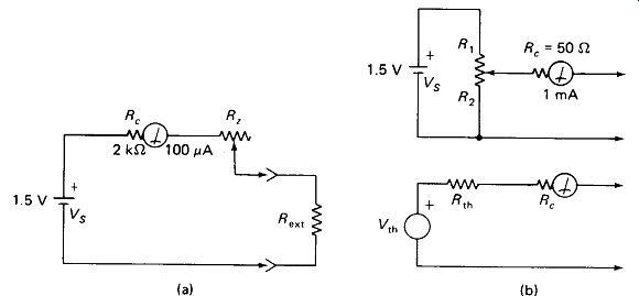
FIGURE 12-4 (a) Basic series ohmmeter circuit, (b) Lower-scale ohmmeter and
its Thevenin equivalent for analysis (Example 12-6).
Any ohmmeter constructed according to this circuit will have a right-hand limit of 0 ohm and a left-hand limit of infinity. Nevertheless, ohmmeter sensitivities do vary, and we can conveniently quantify this by specifying the center-scale ohms reading for a particular circuit. Higher-sensitivity ohmmeters (those having higher center-scale ohms readings) can be produced by increasing the battery voltage or by increasing the galvanometer current sensitivity, and conversely, lower-scaled meters can be produced by lowering either of these parameters.
EXAMPLE 12-4
Find the value of Rz and the center-scale reading for the ohmmeter of Fig. 12-4(a).
Solution
First the total series circuit resistance for full-scale current is found:
V 1 5 RT=~= , . = 15 k-Ohm.
The meter coil has 2 k-ohm of resistance, and the battery is assumed to have zero resistance.
= 15k ohm-2k ohm = 13k- ohm
The total resistance at half-scale current is
R _ y = i.sv _30ko 1/2) ~ TV/1 0.05 mA
The meter and Rz account for 15 kl, so R /i is found:
EXAMPLE 12-5
Find the battery voltage required to produce a center-scale reading of 100 k Q using the circuit and meter movement of Fig. 12-4(a).
Solution
Although shortcuts are possible, the most general solution is to write equations for full-scale deflection with zeroing resistance only (Rt includes Rc in this example) and partial deflection with the required resistance added:
Vs = I„Rz
0.5 Kt = 5V
Any desired deflection (other than half scale) could have been specified by choosing the appropriate value in place of /ctr.
An expanded low-ohms range can be obtained by lowering the effective source voltage, as shown in Fig. 12-4(b).
EXAMPLE 12-6
Find the values of Rx and R2 in Fig. 12-4 such that the available 1.5-V battery produces a one-quarter scale deflection for a resistance of 600 ohm.
Solution
First it is necessary to draw the Thevenin equivalent of Vs, Rt, and R2- Then we proceed as in Example 12-5.
Now it is only necessary to determine Rt and R2 to divide the 1.5 V down to 0.2 V while making their Thevenin resistance equal the required zeroing resistance.
EXAMPLE 12-7
Note that in the circuit of Fig. 12-4(b), R1 and R2 draw current from the battery even with no external resistor connected. Meet the specifications of Example 12-6 by shunting the meter to decrease its sensitivity, thus avoiding this problem. Refer to Fig. 12-5.
Solution
The low-ohms circuit offered in Fig. 12-5 is the one that is generally used in commercial instruments, but it does considerably increase the current in the external resistor, whereas the circuit of Fig. 12-4(b) does not.
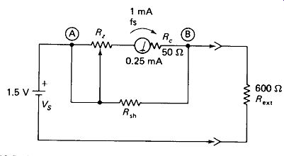
FIGURE 12-5 Low-scale ohmmeter produced by lowering the meter sensitivity.
The Shunt Ohmmeter circuit of Fig. 12-6 is used occasionally where a very low scale ohmmeter is required. It also has the disadvantage of drawing battery current continuously. Its scale has zero on the left, and hence it cannot use the same scale as the higher-range series meters on a X 1, X 10, X 100 basis. The zeroing resistor is adjusted for full scale (infinity) with the probes open circuited. Very low ranges can be realized with this circuit only if the meter-coil resistance is low.
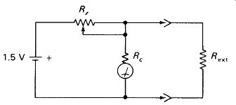
FIGURE 12-6 Shunt ohmmeter for low ohms measurement.
12.5 METER PROTECTION
D'Arsonval movement meters can typically withstand overloads of X 5 or X 10 without damage. Very fast-acting instrument fuses are available in ratings from a few amperes down to a few milliamperes for the protection of meter movements, but this range falls short of being able to protect the very common (and very expensive) meter movements in the 50- to 100-uA range. Solid-state electronic circuit breakers provide the ultimate protection, but a simpler and very effective expedient is shown in Fig. 12-7. The current drawn by a silicon junction diode is less than 1 uA for voltages below 0.4 V, but reaches about 1 A at 1 V forward.
Thus if a meter movement has a full-scale voltage between 0.1 and 0.4 V (which is common) a pair of diodes connected across it will not conduct in the meter’s normal operating range, but will turn on heavily and shunt large overload currents around it. Of course, serious overloads would destroy the diode, but an inexpensive j-A fast fuse can be used to open the line before this happens.
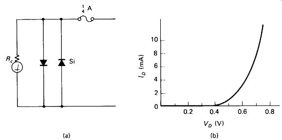
FIGURE 12-7 (a) Silicon power diodes protect the meter movement by limiting
coil voltage to about 1.0 V. (b) Silicon-diode curves.
12.6 EXPANDED AND COMPRESSED SCALES
Occasionally, it is desired to have a meter scale that does not read linearly from zero to full scale. One example of this is a 117-V line monitor, which may read from 105 to 125 V but will certainly never read in the 0 to 100-V range. The circuit of Fig. 12-8(a) can be used to provide an expanded 100 to 130-V scale for easier reading.
Tuning meters and null detectors are more convenient if they are very sensitive to small signals, yet do not overload and pin on large signals. A silicon diode in the circuit of Fig. 12-8(b) can be used to reduce the sensitivity of the meter at midscale by switching part of the input current around the meter.
EXAMPLE 12-8
What is the full-scale input voltage of the metering circuit of Fig. 12-8(b)?
Solution
= 6.0 V
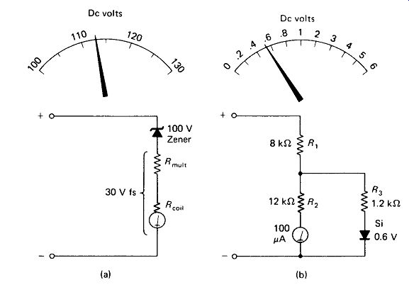
FIGURE 12-8 (a) High-end-expanded meter circuit, (b) High-end-compressed meter
circuit.
12.7 AC METERS
Ac ammeters and voltmeters are generally constructed using two electromagnets, rather than one electromagnet and one permanent magnet as in the D'Arsonval meter. These two-coil meters are called electrodynamometers. The torque that turns the pointer is proportional to the product of the currents in the two coils, which is positive for either current direction if they are connected in series. Torque is then proportional to I^2 , so scale linearity is a problem. Sensitivity is also a problem, since the fixed coil cannot generally rival the field strength of the permanent magnet in the D'Arsonval meters. Electrodynamometer ammeters down to 100 mA ac and voltmeters down to 5 V ac full scale are commonly available.
D’Arsonval-movement micro-ammeters are often used in conjunction with solid-state rectifiers to provide ac voltage indication. However, even the special metallic rectifiers that are generally used have forward voltage drops in excess of 0.1 V, resulting in a 0.1 to 0.2-V dead zone at the bottom end of the scale. This dead zone is not significant on high-voltage scales, but causes serious nonlinearities on scales of 5 V and below. The voltage drop is generally held to be too great to tolerate in a current meter, so rectifier-type ammeters are not generally used.
Figure 12-9 shows a simple half-wave-rectifier type ac voltmeter. The second diode, shown in dashed lines, is used to shunt out reverse meter currents when metallic rectifiers, which are very leaky in the reverse direction, are employed. It also allows source current to flow in both directions so that a capacitor can be inserted in series with the circuit. This will keep any dc that may be present from influencing the ac reading. As illustrated, the meter current lows only on one half-cycle, and varies with the sine-wave voltage. The meter responds to the average value of this current which, for large sine waves, is:

(12-1)
...where VD is the diode voltage drop and R includes both the series multiplier resistance and the meter-coil resistance.
EXAMPLE 12-9 The meter in Fig. 12-9 is 100 /x A full scale, with a 2- k-Ohm coil. The diode is silicon with VD - 0.6 V. What value of multiplier resistance will make a 10-V-rms full scale?
Solution
= 40.93 k-Ohm
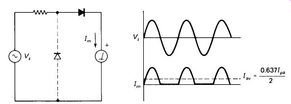
FIGURE 12-9 Rectifier-type ac voltmeter.
12.8 WATTMETERS
The most common type of wattmeter is an electrodynamometer with one fixed coil of heavy wire to sense current and one movable coil of fine wire to sense voltage to the load. The wires may be brought out as shown in Fig. 12-10(a) or (b). Such a meter will respond to true power, even if a reactive load produces a phase difference between V and I, or if Vs contains a dc component or is not a sine wave.
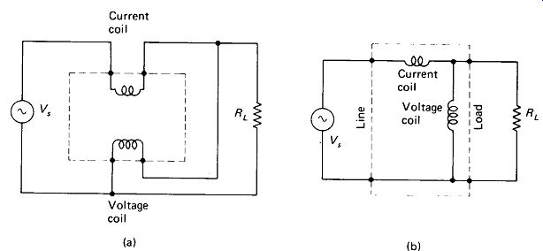
FIGURE 12-10 Two possible connections of a wattmeter.