13.1 THE POTENTIOMETER CIRCUIT
The potentiometer circuit has long been popular for the accurate measurement of small dc voltages. The basic idea, as illustrated in Fig. 13-1(a) is to use a variable voltage divider to tap off a fraction of the voltage from a known source, and to balance this against an unknown voltage. When the voltage divider is adjusted for perfect balance, no current flows through the indicator (galvanometer) or the unknown source, and the voltage can be read from the calibrated pot or slide-wire scale. This ability to measure the voltage of a source without drawing current from it is important, because many voltage sources used in instrumentation have a high internal resistance and the meter loading effect (see Section 12.2) would invalidate a simple voltmeter reading.
Figure 13-1(b) shows two additions to the basic potentiometer. The first is a calibrate rheostat to compensate for aging of the working battery. A highly accurate reference cell is switched in place of the unknown and the potentiometer dial is set to this cell’s voltage. The rheostat is then adjusted for zero on the galvanometer. The second addition is a high-value resistor in series with the meter to limit the meter and unknown source current to a harmless value while the operator is hunting for a balance. Once an approximate balance is found, the switch is closed to permit maximum sensitivity for a more accurate balance.
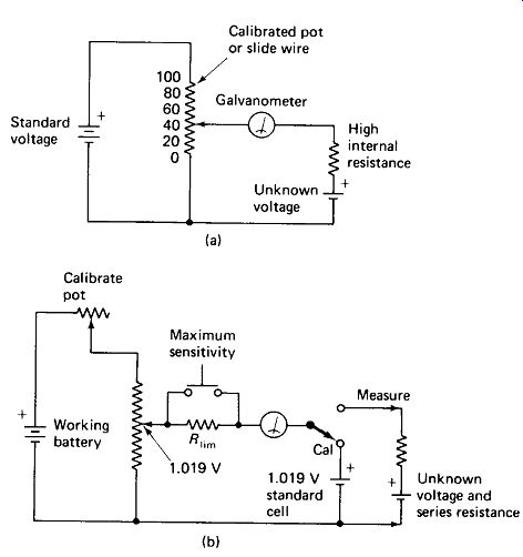
FIGURE 13-1 (a) Basic potentiometer circuit for measuring an unknown voltage
without drawing current from it. (b) Practical potentiometer with a working
cell, meter sensitivity switch to assist in finding a null, and calibrating
position.
The industry is literally filled with instruments which are basically potentiometers. Functionally, they can be sorted into three types:
Laboratory Instruments are highly accurate (0.1% or better), manually balanced, and are used for laboratory measurements or for calibration of voltmeters, power supplies, and so on.
Pen-Chart Recorders have a pen attached or geared to the voltage-dividing resistance arm, and a roll of graph paper which moves at a constant rate under the pen. The bridge is automatically balanced by applying the unbalance voltage to an electronic amplifier instead of a galvanometer. The output of this amplifier is then used to drive a small motor which resets the resistance arm until balance is achieved. These units are widely used to monitor temperature, pressure, and other critical factors in industrial processes.
Process Controllers are used not simply to monitor, but to control some factor in an industrial process. They will be treated in detail in Section 14.
Calculations for the potentiometer involve nothing more than Ohm’s law and a basic application of Thevenin's theorem. An example will serve to illustrate this.
EXAMPLE 13-1
In the potentiometer of Fig. 13-2, the main dial is calibrated in 1-mV steps from 0 to 1200 mV, and can be read to the nearest mV. The galvanometer can detect currents as small as ±0.2 uA. The voltage to be measured is a standard cell with Vs= 1.019 V and Rs = 600 ohm. Find the value of calibrating resistance R 1 the main dial resistance between wiper and ground, and the resolution of the measurement.
(a) (b)
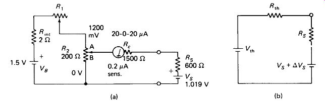
FIGURE 13-2
Example 13-1: analysis of a potentiometer circuit.
Solution
R i + R ln, must take the 0.3 V not taken by R 2;
The setting of R2 is also found by voltage division:
R g R2B = 169.83
To determine the resolution of the measurements, we will find the Thevenin equivalent of the bridge and then determine what change in Vs would unbalance the bridge by 0.2 u A. Figure 13-2(b) shows the equivalent.
The mechanical imprecision of 0.25 mV from the dial calibration must be added to this electrical imprecision:
±0.681 mV
13.2 THE WHEATSTONE BRIDGE
The Wheatstone bridge is widely used for the precision measurement of resistance, just as the potentiometer is used for the measurement of voltage. The Wheatstone bridge can also be used as the basis for automatic recording and control systems where the sensing device is resistive rather than voltaic.
A basic Wheatstone bridge is shown in Fig. 13-3(a). Notice that it consists of two voltage dividers: R1 and R2 on the left, R3 and R4 on the right. When the division ratio of the left divider equals that of the right divider, the bridge is balanced and the indicator reading is null. An easily remembered form of the balance equation is R.
Balance of the Wheatstone bridge is not affected by the battery voltage or the accuracy of the null meter, and if the resistances are chosen to have the same temperature coefficients, even the small changes in resistance due to temperature change will be balanced out.
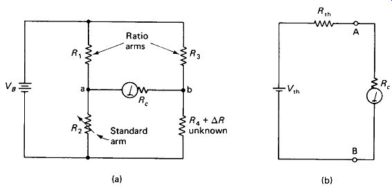
FIGURE 13-3 Basic Wheatstone bridge (a) and equivalent circuit
(b) for analysis under slightly unbalanced conditions.
Slightly Unbalanced Bridge: If a Wheatstone bridge is only slightly unbalanced
[A/? no larger than a few percent of /?4 in Fig. 13-3(a>], we can obtain its Thevenin equivalent [Fig. 13-3(b)] and determine the unbalance current through the meter very quickly by use of the following approximations:

(13-2) (13-3)
If all four resistances are equal, as is often the case, these equations reduce to:
R* = R (13-4) V*-V* 4R (13-5)
The precision of a Wheatstone bridge measurement can be increased by increasing the battery voltage, lowering the values of the four resistors proportionately, lowering the galvanometer coil resistance, or increasing the galvanometer current sensitivity. The electrical precision of the Bridge can be calculated with the aid of Ohm's law and Thevenin's theorem, but here we must "sneak in the back door" by assuming a small change in the unknown (say 1%) and calculating the current produced in the galvanometer by this upset. This current can then be proportioned against the galvanometer sensitivity to find the precision of the resistance measurement. The following example illustrates the technique.
EXAMPLE 13-2
In the circuit of Fig. 13-3(a) the following values apply at balance:
A minimum R3" 500 0 for observable deflection
Find the value of R4 and the precision of this determination.
Solution
The value of R4 is determined quickly from the balance equation:
The sensitivity will be determined by letting RA - 202 ohm and finding the resulting unbalance current. The Thevenin equivalent must first be taken with the meter as the external load.
We will now take the ratio of this current over the minimum observable current and set it equal to the ratio of given resistance change over minimum observable resistance change:
This is the electrical imprecision. Of course, the mechanical imprecision due to dial readability must also be considered.
In commercial bridges, R2 (Fig. 13-3) is a high-precision potentiometer or a combination of switch-selected precision resistors and a precision pot in series. R1 and R3 are precision resistors which are switch-selected to determine the ratio of unknown R4 to main pot R2. For example if R1 is 100 ohm and R3 is 500 ohm, R4 will have a value of (500/100) R2, or 5 R2.
13.3 VARIATIONS ON THE WHEATSTONE BRIDGE
Kelvin Bridge: If a conventional Wheatstone bridge is used to measure resistance much below 1 ohm, the resistance of the lead wiring within the instrument becomes appreciable compared to the unknown, and the accuracy of the instrument is impaired. The Kelvin bridge of Fig. 13-4 solves this problem and allows accurate measurement in the milliohm range.
Notice from the figure that the right-hand voltage divider R3-R4 contains extremely low resistance, and that the wiring resistance Rw between R3 and R4 would cause a 10% error if the galvanometer were simply connected at the bottom of R3. Connecting the meter directly to the top of R4 would not solve the problem, because Rw would then cause a 5% upset in R3. The solution is to split the voltage drop across Rw according to the ratio of R1 over R2, and this is most conveniently ...
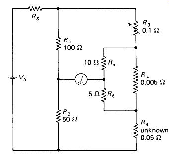
FIGURE 13-4 The Kelvin bridge compensates for the circuit wiring resistance,
allowing measurement of very low values of resistance.
... done with two added resistors Rs and R6, selected such that (13-6) If multiple ranges are desired in a Kelvin bridge, R5 or R6 must be switched also to satisfy equation 13-6. For example, switching Rt to 1000 ohm and Rs to 100 ohm would lower the resistance range of the meter by a factor of 10. Switches should not be placed in the low-resistance line containing R3, Rw> and R4, since switch contacts have unpredictable and in this case relatively large resistances.
Megohm Bridge: Resistances in the gigaohm range can be measured with the basic Wheatstone bridge circuit if the source voltage is increased to around 1000 V.
The range can be extended to the teraohm (10t2 i) range if an amplifier is used to increase the sensitivity of the null detector and if special precautions are taken against leakage currents.
Figure 13-5 shows two of these precautions. T} is a terminal with a metal guard band completely surrounding it. Leakage current which otherwise would flow from Tx across the instrument case to T2 is intercepted by the guarding and routed to the other side of the battery. The leakage resistance thus shunts the battery instead of shunting the test resistance and does not affect the measurement.
T3 is a guard terminal (not the same as T, which is a guarded terminal) which is used to intercept leakage currents that may flow around the body of the component under test. The guard terminal is connected to a metal plate on which the test specimen is mounted by stand-off insulators, or to a metal ring around the body of the test specimen if it is desired to eliminate surface leakage effects.
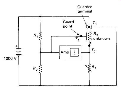
FIGURE 13-5 Very high values of resistance can be measured if special precautions
are taken against leakage currents.
13.4 AC BRIDGES
AC Bridges have the same four-arm configuration as the Wheatstone Bridge, but each arm may contain reactive as well as resistive components. Balance requires that not only the amplitude but also the phase of the voltages at each side of the detector be identical. In general, manual balance of an ac Bridge requires adjustment of two Variable components, although bridges to measure pure reactance balance with one.
Capacitance-Comparison Bridges can have a wide range of measurable values using only one standard fixed capacitor and a Variable resistance as the calibrated readout dial. Figure 13-6(a) shows the simplest such Bridge with its balance equation. R_var and std are selected so that Xc is approximately equal to Rvu at mid-rotation. This, of course, depends upon the frequency of Vs. Notice that the detector is an ac amplifier diving a rectifier and meter.
When the unknown capacitance contains an appreciable leakage resistance, it will be necessary to similarly shunt the standard capacitance to obtain a balance.
Figure 13-6(b) shows a parallel capacitance-comparison Bridge and its balance equations. Notice that lower values of shunting resistance indicate lower Q (higher dissipation factor D) in the measured capacitor.
Often the dissipation of the measured capacitor is so low that the required value of R2 would exceed the available limits for precision Variable resistors. In this case the series capacitance comparison Bridge of Fig. 13-6(c) is used. Here the low dissipation factor calls for a low value of R2, which is easily realized. The balance equations yield the series equivalent circuit Cs + Rs, whereas we may wish to work with the parallel equivalent. The series-to-parallel conversion equations of Section 4.
2 can be used to rectify this problem, although it will be necessary to perform Xs = 1 /(2tt/Cs) before and Cp = 1 /(2 pi fXp) after the conversions.
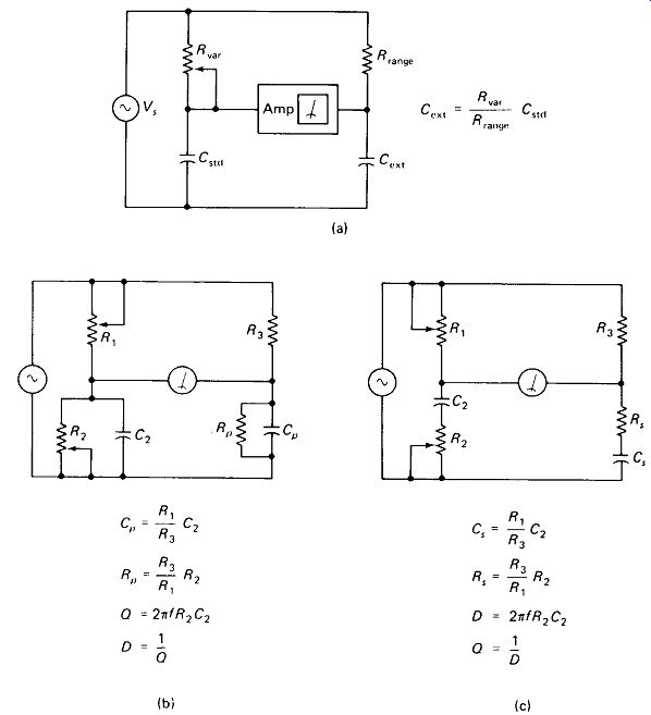
FIGURE 13-6 Capacitance Bridges: (a) simple comparison; (b) parallel resistance
for high-D (dissipation) measurements; (c) series resistance for low-D (high-Q)
measurements.
Inductance-Comparison Bridges can be built in a manner similar to the capacitance-comparison Bridges, but they are of limited practical value because real standard inductors are expensive, relatively temperature unstable, and plagued by stray effects such as skin-effect resistance, interwinding capacitance, and core hysteresis. Inductance measurement can be handled more effectively by using an " upside-down "
C-R voltage divider in the left-hand leg of the Bridge, as shown in Fig. 13-7.
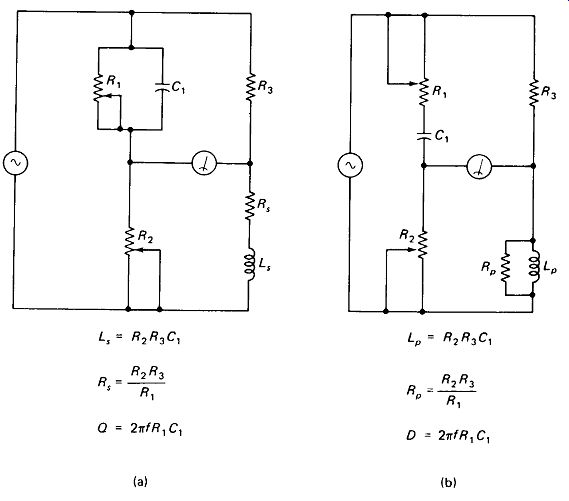
FIGURE 13-7 Inductance bridges: (a) Maxwell bridge, primarily for low-Q inductance
measurement; (b) Hay bridge, primarily for high-Q Inductors.
The Maxwell Bridge, Fig. 13-7(a), is suited for measuring relatively low-Q coils. C, and R2 provide a leading, phase shift at the left side of the null indicator to match the leading phase at the right side produced by R3 and Ls .
R1 introduces loss in the standard capacitor to match the loss in the measured inductor. Lower values of R2 indicate a lower Q of the measured coil. Very-high-g coils require excessively high values for R,, making a series R1C1 combination desirable. Balance equations for Ls and Rs are given with the figure.
The Hay Bridge, Fig. 13-7(b), is more suited for measuring high-Q coils, since higher Q requires lower values of R1. The balance equations given with the figure are for a parallel equivalent to the unknown inductance, Lp and Rp.
This is inconvenient, since we seldom conceive of a real inductor as being a perfect inductor shunted by a leakage resistance. Also note that the Lp value obtained with the Hay bridge will not exactly equal the Ls value obtained with the Maxwell bridge for the same coil. For these reasons a more complex but perhaps more useful set of formulas for the series-equivalent inductance from the Hay-bridge components is given:

(13-8)
Of course, the parallel-to-series-conversion formulas of Section 4.2 could be used to achieve the same results.
Biased-Component Measurement: It is often desirable to measure the inductance of a coil as a function of the dc current it carries to identify core saturation.
Similarly, we may be interested in the variations in capacitance and dissipation factor of an electrolytic capacitor as the dc voltage across it is changed. Commercial impedance bridges often have special bias-current and bias-voltage terminals for these applications, but at low frequencies the connections of Fig. 13-8 can be used.
To voltage bias a capacitor, a lab supply can usually be placed in series with the capacitor under test, observing polarity, as in Fig. 13-8(a). Be sure to keep the supply at the LOW side of the bridge terminals, to avoid putting its considerable stray capacitance to ground in parallel with the test capacitor. If the bridge does not provide an internal dc path from the HIGH to LOW terminal (easily checked with an ohmmeter), an external path can be provided as shown. If the connection point shown (arrow) is not accessible, the HIGH terminal can be used, but the dissipation factor will read erroneously high.
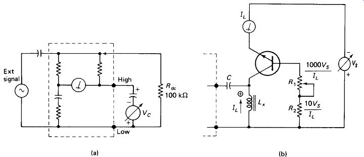
FIGURE 13-8 (a) Measuring capacitance under an externally applied voltage
Vc. (b) Measuring inductance under an externally applied current.
To bias an inductor, the circuit of Fig. 13-8(b) is recommended.
The transistor acts as a current source, feeding current to Lx without placing appreciable shunt impedance across it. Vs should be a current-limited supply, or if not, a fast fuse should be placed in its negative lead to protect the inductor from accidental overload. Vs should be adjusted so that VCE is only a volt or two above saturation to minimize power in the transistor. Blocking-capacitor C prevents dc from getting back into the bridge, and is not usually necessary. If it is used, it must have a reactance 100 times less than XL at the test frequency.
Wagner Ground: Stray capacitance on the order of 100 pF can easily accumulate from the amplifier input and from the potentiometers, standard capacitors, switches, and wiring in a wide-range general-purpose impedance bridge. The bridge would be useless at frequencies above a few kilohertz if steps were not taken to compensate for these capacitances. The Wagner ground adjustment, Rw of Fig. 13-9, attempts to place the circuit ground at the potential of the amplifier input by means of a voltage divider RW CW.
The voltage across the amplifier input capacitances is then zero and no current flows through them. If /?2 is very low (low-£) capacitor being measured), this ideal can be approached closely with only a single adjustment, Rw.
In operation, switch 5,, is thrown to GROUND and Rw is adjusted for minimum meter reading. The switch is then returned to MEASURE and R1, and R2 are adjusted for null.
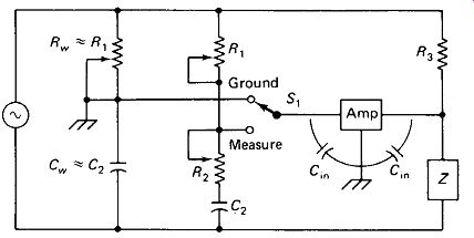
FIGURE 13-9 Wagner ground connection for eliminating the effects of meter-amplifier
input capacitance.