18.1 RC FILTERS AND BODE PLOTS
RC filters occur with great regularity in electronic circuitry, both by design and by accident. By design they are formed from small, light, and inexpensive components with tolerances that can easily be held to 5% over a wide range of temperatures. By accident, they are formed whenever a source resistance drives a load shunted by a stray capacitance, or whenever a resistive load is capacitively coupled to its source.
The Single-Section Low-Pass Filter is shown in Fig. 18-1(a). At low frequencies the reactance of the capacitor is so high that there is negligible drop across the resistor and to a good approximation V0 = Vm.
The phasor diagram of Fig. 18-l(b) shows that even when Xc is only twice R, fully 89% of Kin appears at Va.
The critical frequency fc is the frequency at which Xc = R. At this frequency Va is down by 3 dB (i.e., Va = 0.707 K_in).
Above the critical frequency Va drops off quite rapidly. Figure 18-l(d) shows Va = 0.45Fin at 2 fc.
The Bode Diagram (say BO-dee) of Fig. 18-2 summarizes the behavior of an RC filter in two straight lines. It is based on the realization that, at frequencies four or five times fc,
Xc adds little to the total circuit impedance, so the output of the filter is approximately
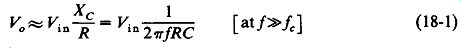
(18-1)
This equation shows that V0 varies in inverse proportion with/ above fc
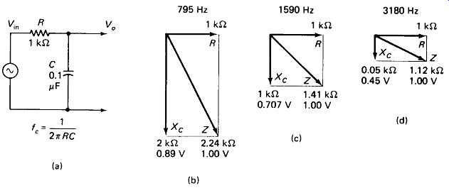
FIGURE 18-1 Elementary phasor analysis can be used to predict the output of
a simple RC filter at various frequencies.
We speak of the filter having a rolloff of 20 dB per decade, which is to say that Va drops by a factor of 10 for each increase in / by a factor of 10. Sometimes this same fact is expressed as a 6-dB per-octave rolloff, which is a factor-of-2 voltage drop for a factor-of-2 frequency rise (in music an octave-eight-note scale-covers a frequency span of 2 : 1).
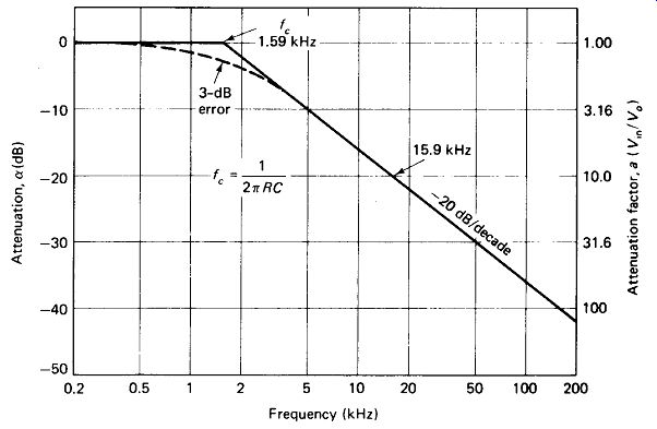
FIGURE 18-2 The Bode plot summarizes the response of an RC filter:
20-dB/decade rolloff, 3 dB down at the break frequency.
To draw the Bode plot for an RC filter it is only necessary to determine the values of R and C, calculate the critical frequency fc (this is often called the break point), and draw a straight line sloping down at 20 dB/decade from/.. Notice that the graph paper is log-log if the attenuation factor a is being graphed. If a is being expressed (in dB), semilog paper is used. In both cases the frequency must be plotted on a log scale for the straight-line rolloff to be accurate. As a final correction, we draw in a smoothly rounded " actual " curve passing through fc at - 3 dB below the break point to correct for errors in the straight-line approximation curve around/.
The Single-Section High-Pass Filter is very similar to the low pass. The calculation of fc, the 20-dB/decade roll-off, and the - 3-dB correction at fc are all the same.
Here the roll-off is to the left rather than the right, however. Figure 18-3 shows the circuit and its Bode plot.
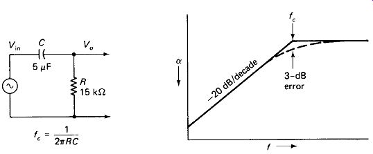
FIGURE 18-3 RC high-pass filter, with Bode plot rolling off at the low end.
Load and Source Resistances are unavoidable parts of most real circuits, but they can be reduced to the simple two-component RC circuits of the previous examples without difficulty. Figure 18-4 shows how the load and source resistors can be combined with R so that a calculation of fc can be made. To determine the output at the horizontal portion of the curve, assume the capacitor to be an open circuit for a low-pass (or short circuit for a high-pass) filter and compute V0 using simple resistive voltage division. Notice that the low-pass filter requires an application of Thevenin’s theorem to combine R, with the other two resistors.
Occasionally, a capacitor is used to drive a load which itself has appreciable shunt capacitance, as in Fig. 18-5. In this case the capacitors are Thevenized, as illustrated by the attendant calculations. It must be emphasized that this technique is valid only if Rs is many times (100 or more) less than RL, and then is good only up to the frequency where the two capacitors begin to load Rs.
Above /miuc, the circuit becomes a low-pass filter.
18.2 MULTIPLE-SECTION RC FILTERS
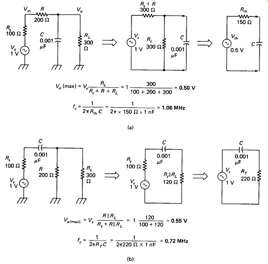
FIGURE 18-4 RC filters with resistive source and load impedance can be reduced
to simple RC filters: (a) low pass; (b) high pass.
Cascaded RC Sections can be used to obtain a steeper rolloff-40 dB/decade for two sections with identical cutoff frequencies, 60 dB /decade for three sections, and so on. The correction when rounding in at the break point is - 6 dB for two sections, - 9 dB for three sections, and so on, if the resistor in the second section is several times higher in value than the resistor in the first section. For equal resistor values the correction at the break point for two sections is -10 db (factor of 3).
For a section with resistor value R driving a section with resistor value \ R, the correction at the break point is -12 dB (factor of 4) as illustrated by the circuit analysis of Fig. 18-6. The techniques used are those of Section 4.2.
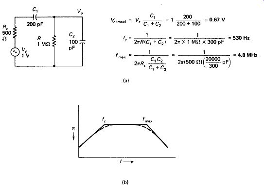
FIGURE 18-5 Commonly encountered RC network: a resistive source capacitively
coupled (C,) to a resistive load shunted by an input capacitance (C2) The circuit
has both a high and a low cutoff frequency.
At frequencies well above or below fc no extra correction to the straight-line plots is required. In Fig. 18-6(a) this is because the reactance of the first capacitor across the line becomes very low (20 52 at 10/c ), providing a very low impedance source which dives the 100-ohm resistor of the second stage with negligible loading.
A similar argument prevails for cascaded high-pass sections. Where the two values of fc are not identical, the Bode plot will roll off at -20 dB/decade between the two fc points, and then break to -40 dB/decade as shown in Fig. 18-6(f).
In staging cascade sections it is a good idea to keep this rule in mind: small capacitance follows large capacitance. Arranging sections in this order will minimize loading and unwanted attenuation.
Bandpass RC Filters can be constructed by following an RC high-pass section (or sections) with an RC low-pass section (or sections) having substantially higher fc.
The ratio of f_c_hi / f_c_lo should be not much less than 10 : 1 or there will be significant attenuation at midband. Also notice the order of the attenuators: low pass follows high pass; small capacitance follows large capacitance. If the filter were built with high pass following low pass, serious attenuation (over -6 dB) would result at midband. Figure 18-7 shows a two-section RC bandpass filter with fc(lo) = 3.2 kHz and f_c(hi) = 32 kHz.
The midband and fc corrections indicated were determined using the techniques of Section 4.2.
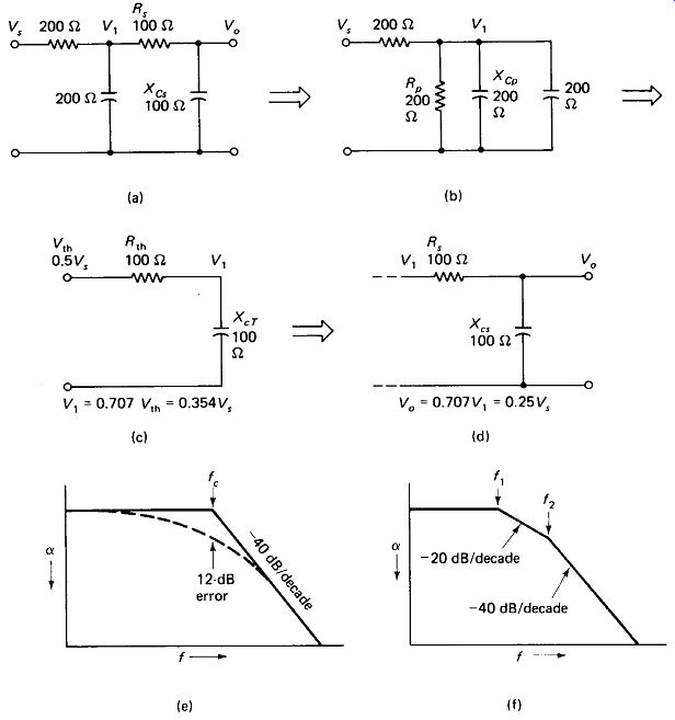
FIGURE 18-6 Cascading two low-pass sections gives a rolloff of 40 dB/decade.
(a)-(d) Reduction of a two-RC circuit at fc.
In the example, a 200-ohm section is loaded by a 100-ohm section, resulting in 12-dB attenuation at fc (e). (f) Two break points appear when fc of first and second sections are not equal.
18.3 RC NOTCH FILTERS
There are two popular RC filters which are capable of producing a very high degree of attenuation at a narrow range of frequencies provided that they are operated into a very high impedance load.
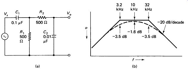
FIGURE 18-7 Bandpass RC filter formed by cascading high- and low-pass sections.
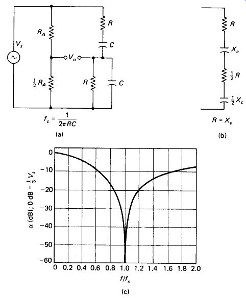
FIGURE 18-8 Wien bridge notch filter: (a) circuit with equal R and C values
in each arm for easy tuning; (b) equivalent of right-hand arms at fc; (c) frequency-response
curve.
The Wien Bridge is a four-arm ac bridge that is balanced at only one frequency.
A special case of the Wien bridge is shown in Fig. 18-8, in which the two resistive and two capacitive frequency-determining elements are equal. This permits tuning of the bridge by ganged identical pots or variable capacitors.
The operation of the bridge is easy to understand. It is based on the equivalency of series and parallel RC circuits. At the frequency where the parallel RC combination is equivalent to the half-value series circuit shown in Fig. 18-8(b). The voltage at the right output terminal (to ground) is therefore 1/3 Vs and in phase with Vs. The voltage at the left terminal is 1/3 Vs in phase at all frequencies, so the voltage between the two Va terminals is zero at the frequency where Xc = R. At higher frequencies Cp has a low reactance and drops the right-terminal voltage below 1/3 Vs. At lower frequencies Cs has a high reactance and lowers the right-terminal voltage. The right-terminal voltage is also out of phase with Vs at frequencies above or below fc.
All of these factors keep the bridge unbalanced except at fc.
The attenuation of the Wien bridge (Vin/Vo) is theoretically infinite at fc with no load across V_o. However, there is also substantial loss at frequencies near fc, as shown in Fig. 18-8(c).
The Twin-T Notch Filter behaves much the same as the Wien bridge, but it has two important advantages:
. The grounded side of the input is common to one side of the output, making the twin-T compatible with single-ended amplifiers and unbalanced lines. The floating outputs of the Wien bridge require a differential amplifier to pick them up.
. The output in the passbands is fully equal to Vs, not | Vs as in the Wien bridge.
However, the twin T requires three resistors and three capacitors, making it more difficult to tune with variable capacitors or pots. Figure 18-9 shows one form of the twin-T filter.
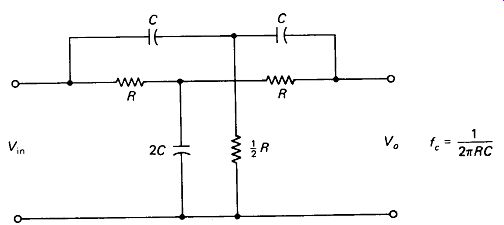
FIGURE 18-9 The twin-T notch filter has a common ground between input and
output, but ganged tuning is difficult.
18.4 RC SELECTIVE FILTERS
Amplifiers with a selective peak can be built with RC notch filters as the feedback elements. Figure 18-10(a) shows a highly selective amplifier using a twin-T notch filter in this manner. The gain of the amplifier will approach infinity, resulting in instability at fc if a fixed feedback Rj is not shunted around the twin T as shown.
The 8-k ohm resistor may be varied slightly to produce oscillation or almost any degree of selectivity.
Figure 18-10(b) shows a simpler but more broad-banded tuned amplifier.
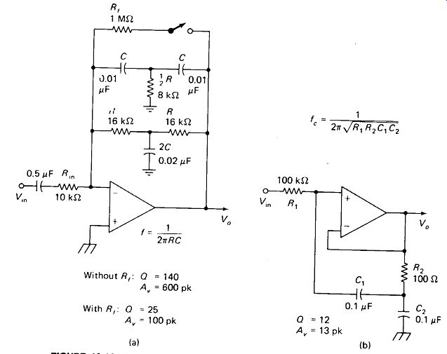
FIGURE 18-10 (a) Peaking amplifier tuned by T-notch feedback, (b) Broadly
peaked amplifier.
18.5 LC FILTERS
High- and low-pass filters in the pi and T configurations can be constructed using LC rather than RC components. The advantage is that the rolloff rate is much steeper -60 dB/decade (18 dB/octave) rather than 20 dB/decade since there are three reactive components rather than one per section. The disadvantages include expense and weight of inductors, difficulty in obtaining high-Q inductors of high accuracy and stability, stray coupling between inductors, and saturation and nonlinearity of iron-core inductors.
Figure 18-11 shows the basic filter sections and the applicable formulas. All sections are designed to be driven by a source resistance RS = Z_o and to feed a load resistance R_L = Z_o, although these are omitted from the figures. The correction for rounding in the Bode plot at the break point is - 3 dB for a single section.
Impedance Mismatch: Notice that the low-pass T has Z_in -> oo at high frequencies.
The other sections have similar mismatch problems: Zjn->0 at high/for the pi low pass, Zin-> oo at low / for the T high pass, and Zin->0 at low/for the pi high pass.
The SWR produced by this mismatch is 1.25 : 1 at a frequency factor of 2 into the passband, 2: 1 at f/fc = 1.4, and 5: 1 at /.. Well into the pass band the SWR is nearly unity, but it heads for infinity in the stop band.
Where reflections and standing waves on the line back to the source are undesirable, a pad may be used ahead of the filter to preserve Za, or the filter can be placed near the source, minimizing the time between incident and reflected signals and the length of high SWR line.
M-Derived End Sections, named for a mathematical constant m used in their design, are used to keep the SWR down to about 1.1 over the passband range to within about 10% of/.. Figure 18-12(a) shows a pi-section low-pass filter with its m-derived end sections.
End sections for the T low pass do exist, but require more inductors and are therefore less popular. Figure 18- 12(b) shows a T high pass with end sections, with the pi high pass not shown for the same reason. Notice that the capacitors from the end section and from the filter proper can be combined into a single capacitor in each case. The attenuation at/. is still about - 3 dB for filters with end sections.
Beyond fe (in the stop band), the end sections do not preserve the constant impedance Za.
In fact, they comprise tuned circuits resonant 25% beyond fc which make Zin->oo for the pi-end and Zin ->0 for the T-end sections.
This puts a very sharp notch in the filter , s response curve at 1.25/. (or 0.8/. for high pass), but introduces 100% reflection of the out-of-band signal.
Filters in cascade, up to five sections, can be constructed to obtain extremely high roll-off rates beyond /.. End sections are usually used with these high performance filters. They are structured by breaking the circuits of Fig. 18-12(a) or (b) along the dashed lines and inserting the required number of pi or T sections from Fig. 18-11(b) or (d), respectively.
The stringent requirements on the components and construction practices for such filters must be emphasized. Coils should be air-core No. 14 or heavier wire for RF, or toroid inductors for AF. Capacitors should be mica at RF, or Mylar at AF.
All components should be within 5% of target value. Cylindrical coils should be mounted at right angles to each other, and each section of the filter should be shielded from the other sections by a metal plate (or full enclosure for very high attenuations), with a hole to receive the input wire. The entire filter must be enclosed in a metal box to eliminate stray pickup and radiation. A four-section filter has an attenuation of 72 dB one octave (factor of two) from the cutoff frequency. This is a voltage factor of 4000. If a 4-V input were allowed to couple 1 mV to the output by stray capacitance or inductance, the filter's performance would be ruined.
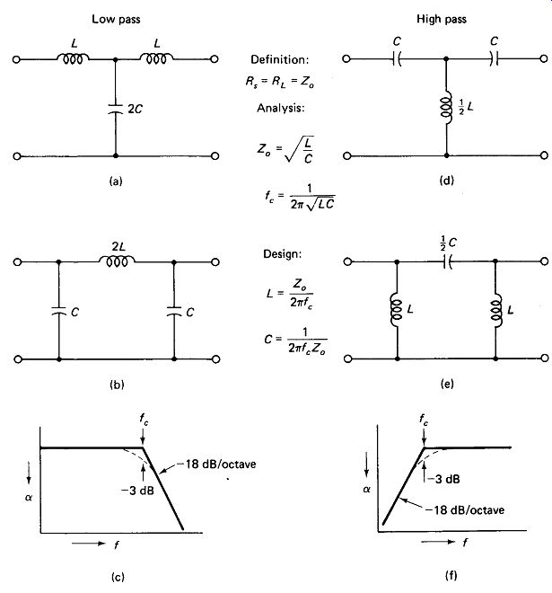
FIGURE 18-11 LC filters have a basic rolloff rate of 60 dB/decade. Low-pass
filters: T section (a), pi section (b), and response curve (c). High-pass filters:
T section (d), pi section (e), and response curve (f). Formulas apply to all
four types.
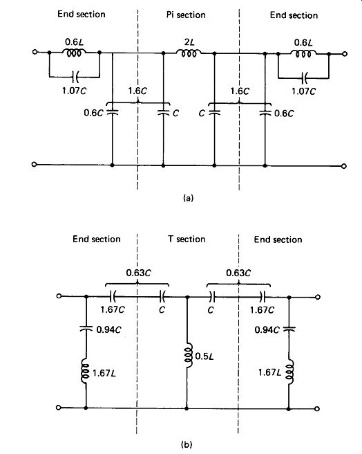
FIGURE 18-12 M-derived end sections preserve impedance match within the pass
band and place a sharp attenuation notch just outside It. (a) end sections
for low-pass pi; (b) end sections for high-pass T filters.
18.6 CRYSTAL FILTERS
Quartz crystals, when ground into wafers and mounted between two conductive plates, have the characteristics of very-high-0 tuned circuits at a frequency that is fixed primarily by the thickness of the wafer. Frequencies commonly available range from 100 kHz to about 30 MHz. Figure 18-13(a) shows the electrical equivalent of a 1814-kHz crystal. Of course, no real electrical inductor of 0.22 H ...
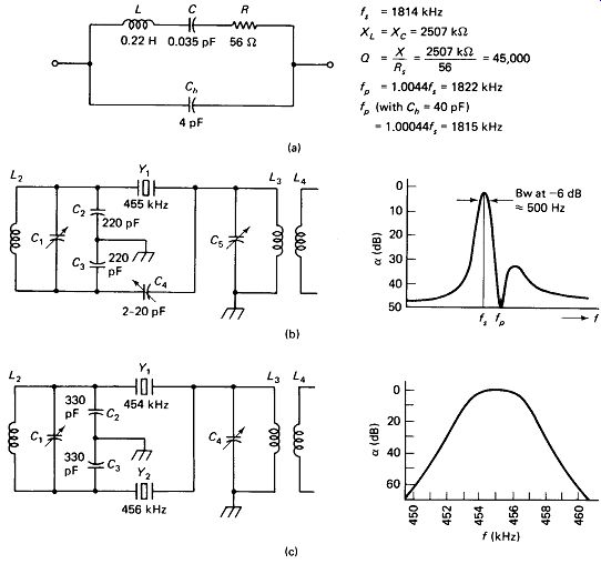
FIGURE 18-13 (a) Equivalent circuit for a crystal with typical values for
an 1814-kHz unit. Holder capacitance C_h places a parallel resonance very near
the natural series-resonance point, (b) Crystal gate filter and response curve.
Varying C_4 moves notch fp. (c) Half-lattice circuit and broadband flat-topped
response curve.
... could be constructed without incurring a stray capacitance many times higher than 0.035 pF, which is why electrical tuned circuits cannot achieve Q's of 45,000. At the series-resonant frequency of L and C, the impedance of the crystal drops to R (56 ohm in the example). At frequencies 0.5 % or more above or below fs, the shunting reactance of the holder-plate capacitance Ch (about 22 k-ohm at this frequency) becomes lower than the reactance of the series L and C, and represents the crystal impedance.
At a frequency slightly less than 0.5 % above f_s, the reactance of the series L and C becomes inductive and equal to C_h. This constitutes a parallel resonance, and the crystal impedance approaches infinity at this frequency f. The parallel-resonant frequency can be moved closer to fs by adding to the shunt capacitance Ch, but this lowers the off-resonance impedance if it is carried too far. Oscillators built to exploit this effect can be "pulled" a small fraction of a percent either way by a trimmer capacitor across the crystal.
The Crystal Gate Filter of Fig. 18-13(b) passes only the series-resonant frequency. C1 and C5 tune their coils to the passband frequency and are required to eliminate spurious frequencies which may be passed by the crystal. The signal applied to C4 is 180° out of phase with that applied to the crystal, so when C4 = C_h the leakage through C_h is canceled and the attenuation at frequencies off fs is increased. Varying C4 moves the parallel-resonant notch with respect to f_s, which may be desirable if a strong nearby signal is to be eliminated.
The Half-Lattice Filter of Fig. 18-13(c) provides a relatively flat bandpass between the two crystal frequencies, with sharply increasing attenuation outside the passband. This is in contrast to the narrow peaked response of the crystal gate and the broad response of the LC tuned circuit, and is ideal for many radio-frequency applications. The passband (difference between the two crystal frequencies) is limited in practice to about 1/2 % of f_s.
As many as five half-lattice filters may be placed in cascade to obtain extremely sharp cutoff outside the passband.
18.7 MECHANICAL AND CERAMIC FILTERS
Mechanical Filters are used where a relatively broad flat-topped response is required and cost is not a prohibitive factor. Six-decibel bandwidth up to 5% of the passband frequency with roll-off to - 60 dB at 6% bandwidth are commonly available. This "straight skirt " selectivity is expressed by the filter's shape factor-the ratio of its bandwidth at -60 dB to its bandwidth at -6 dB. In the example above, the shape factor is f, or 1.2. Shape factors of down to 1.12 are available for special applications. Mechanical filters are commonly available in the range 50 to 500 kHz.
Internally, a mechanical filter consists of an input electromagnet which produces mechanical vibrations in a series of connected resonant metal discs. Each resonant disc alone has a sharp peak (Q over 10,000), but the resonant frequencies are spaced over the passband to form a broad flat response. The output is taken from a second electromagnet coil.
Ceramic Filters, which are similar to lower-g crystal filters, are inexpensive and require no tuning, and have therefore become popular in AM radios.
Ceramic Ladder Filters contain a series of ceramic elements and provide shape factors nearly as good as those of some mechanical filters at a considerably lower price. Most ceramic filters are designed for 455- or 500-kHz center frequency.