2.1 FIXED-RESISTOR TYPES
Resistors are available in a variety of physical forms, each with its advantages and drawbacks. However, the vast majority of the market is covered by three basic types, shown in Fig. 2-1.
Carbon Composition: These are the bread-and-butter resistors used in the majority of noncritical applications. They are universally tubular in shape, with their value marked by three color bands according to the standard color code. They are formed of a mixture of carbon powder with nonconductive fillers and resin binders encapsulated in an insulating tube. The ratio of fillers to carbon is the prime determiner of resistance. Carbon-composition resistors are normally available in tolerances of 5% and 10% and in power ratings of 1/8, 1/4, 1/2, and 2 W. Figure 2-2 shows the actual sizes of the various wattages of carbon-composition resistors.
Composition resistors can be expected to change value by severed percent with ambient temperature changes and internally caused heating. Figure 2-3 documents this effect for a wide range of resistance values. The principal advantage of carbon resistors is cost, which may be as low as 2 or 3 cents each for 5-W 10% types purchased in quantities of 1000.
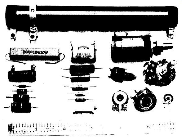
FIGURE 2-1 Representative fixed and variable resistors. Top: 100-W adjustable
wirewound; left: 10-W and 5-W wirewound, followed by 1-, and 2-W carbon-composition
types; center: precision wirewound with five precision metal film types from
1 W to 1/4 W below; top right: precision 10-turn potentiometer with miniature
and standard single-turn pots below; bottom center to right: 10-turn trim
pot, two PC-mount single-turn trimmers, and an inexpensive carbon-track adjustable
resistor.
Metal Film: These resistors are available from stock with a tolerance of ± 1%, and can be special ordered with tolerances as close as 0.05%. They are commonly used where accurately known and tightly held values of resistance are required.
They can be purchased with guaranteed resistance change with temperature in the range 25 to 100 ppm/° C (parts per million per degree Celsius), as compared to typical coefficients of 200 to 500 ppm/°C for carbon-composition types. Their internal noise generation is also quite low, an important factor in handling low-level audio and radio signals. Metal film resistors are commonly available in I ~> and 1-W sizes, and are stocked in values listed in Fig. 2-4. Prices are typically 5 to 10 times the cost of carbon-composition units. Carbon-film resistors with many of the noise and temperature-stability advantages of metal films are becoming available in 5% tolerances at a cost competitive with composition types.
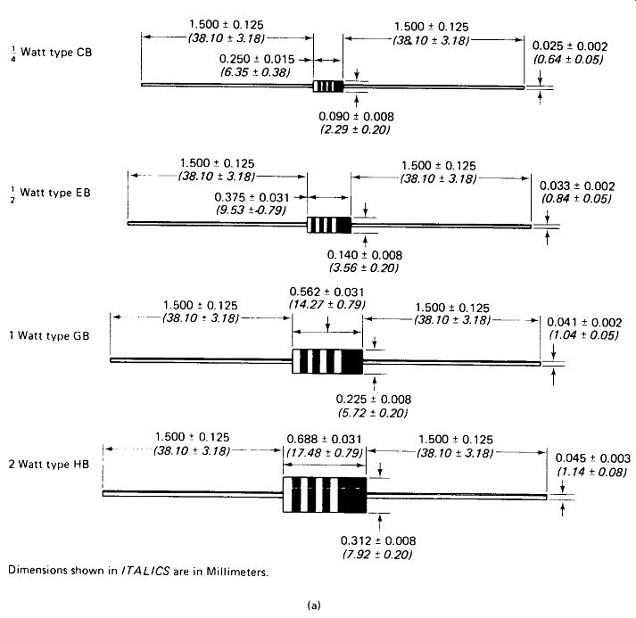
FIGURE 2-2 (a) Actual sizes of 2-, 1-, 0.5, 0.25, and 1/8-W carbon-composition
resistors. (Courtesy of Allen-Bradley Co.)
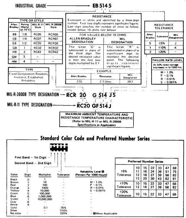
FIGURE 2-2 (b) Standard values and marking system for carbon-composition
resistors. (Courtesy Allen-Bradley Co.)
Percent resistance deviation from 25°C value for various nominal resistance values and temperatures
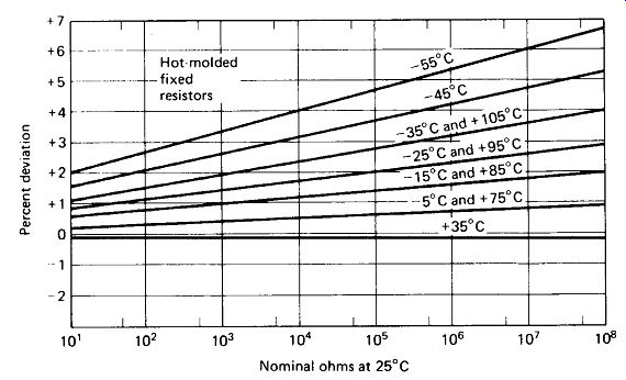
FIGURE 2-3 Resistance change as a function of temperature
for representative carbon-composition resistors. (Courtesy Allen-Bradley
Co.)
Wirewound: Wirewound resistors are commonly used in high-power applications (above 2 W). Some readily available sizes are as follows:
Power (W) Length (cm) Diameter (cm)
For color-coded wirewound resistors, the first band is double width, to distinguish wirewound from composition types. Typical tolerances for wirewound power resistors are 5 to 10%, with 1% available in the lower-power ratings. Costs range from approximately 30 cents for 5-W types to about $2 for 225-W types in 10% tolerance. Temperature stability for power resistors is typically on the order of 200 ppm/°C.
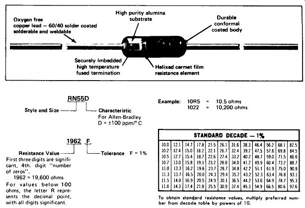
FIGURE 2-4 Physical construction, standard values, and marking system for
1% film resistors. (Courtesy Allen-Bradley Co.) -------- Resistance Value--'
First three digits are significant, 4th. digit " number of zeros " .1962
= 19, 600 ohms
For values below 100 ohms, the letter R represents the decimal point, with all digits significant.
Precision-value wirewound resistors are manufactured by the simple expedient of trimming the length of a resistance wire wound on a bobbin. These resistors are not generally meant to dissipate high power, however.
Resistor Networks: In applications where a number of resistors of the same value are required, size and assembly time can be minimized by using resistors packaged in the dual-in-line package (DIP) developed for integrated circuits. These resistors are manufactured either by thin-film technology, which involves depositing a strip of metal a few millionths of an inch thick on a glass or ceramic base, or by thick-film techniques, in which resistive material is painted on an insulating surface, usually by silk-screen printing.
2.2 VARIABLE-RESISTOR TYPES
Variable resistors come in the following basic types:
. Carbon-composition potentiometer
. Wirewound potentiometer
. Multiturn potentiometer
. Linear slide pots
. Single-turn trimmers
. Gear-actuated trimmers
. Adjustable resistor
These are illustrated in Fig. 2-1. The term potentiometer derives from the early use of the component in a potential-measuring circuit. Verbally, the term is almost always shortened to pot. Trimmer pots are usually small, and almost always designed to be adjusted only occasionally by a screwdriver rather than frequently by a front-panel knob. High-power pots, especially those having only two terminals, are sometimes called rheostats.
The wiper of a wirewound pot divides the resistance neatly into two parts, so a 100-ohm pot at mid-rotation will measure 50 ohm from either end to the wiper. The wiper of a carbon-track pot provides only a point (or two points) contact on the track, and there is extra resistance associated with this incomplete contact to the cross section of resistance. A 100- ohm carbon pot at mid-rotation will typically measure 55 ohm from each end to the wiper.
2.3 RESISTOR POWER RATINGS
Manufacturers, power ratings for resistors apply for "standard" conditions which are seldom realized in practice. Therefore, it is wise to adjust the resistor power rating as calculated from P = IV to accommodate actual conditions of operation.
Standard conditions for wirewound power resistors are:
. Ambient temperature of 25° C (77 °F)
. Resistor suspended in free air (no enclosure)
. Single resistor suspended away from other heat-producing devices
. Ai r pressure equivalent to sea level (76 cm Hg)
. 100% duty cycle
. Still air; no forced-air cooling
. Allowable temperature rise of 300° C
Figure 2-5 shows the recommendations of the Ohmite Manufacturing Company for adjusting wirewound power resistor ratings to accommodate deviations from these conditions. This chart is given only as a guide,1 since the factors involved are seldom accurately known. The percent load for pulse operation, in particular, is a complex function of duty cycle (% on-time), cycle time, and resistor size. For cycle times of less than 0.1 s the percent load is nearly the reciprocal of duty cycle, but for longer cycle times the resistor will have a chance to heat up during the on-time, and the percent load will be much less than 1 /duty cycle. In practice, most resistor users settle on a safety factor (usually 2, 3, or 4) for resistor power ratings which they have found from experience to be suitable to the service conditions of their products.
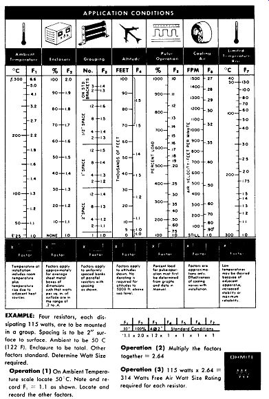
FIGURE 2-5 Resistor power rating calculation chart. (Courtesy Ohmite Manufacturing
Co.)
EXAMPLE: Four resistors, each dissipating 11.5 watts, are to be mounted in a group. Spacing is to be 2" surface to surface.
Ambient to be 50 C (122 F). Enclosure to be total.
Other factors standard. Determine Watt Size required.
Operation (1) On Ambient Temperature scale locate 50 C. Note and record F, = 1.1 as shown. Locate and record the other factors.
Operation (2) Multiply the factors together = 2.64 Operation (3) 115 watts x 2.
64 =314 Watts
Free Air Watt Size Rating required for each resistor.
EXAMPLE 2-1 A totally enclosed instrument is to operate at an ambient temperature of 75°C. The instrument contains four resistors, each dissipating 6 W, mounted with 1-in. space between resistors. A fan provides forced-air cooling at a velocity of 500 ft/min, and the resistors may not exceed a temperature of 250°C because of insulation used within the instrument. The altitude is sea level and the duty cycle is 100%.
Find the watt-size resistor required.
Solution From the chart, the factors involved are:
Fx for 75°C 1.2 F2 for total enclosure 2.0 F3 for 4 at 1-in. spacing 1.3 F4 and Fs normal 1.0 F6 for 500 ft/min 0.5 F1 for 175°C rise (250° final -75° ambient) 2.5
The minimum watt size required for each resistor is 6x 1.2X2.0 x 1.3 X 1.0 x 0.5 x 2.5 = 23.4 W
Where available resistors fall short of power requirements, a heat-sinking clamp and/or thermally conductive adhesive to the chassis can be used to approximately double the power-handling capability of 1-W and 2-W carbon resistors. For laboratory bench tests, immersing small resistors in a bath of distilled or deionized water will increase their capability by approximately a factor of four.
2.4 RESISTOR TOLERANCE AND RELIABILITY RATINGS
A manufacturer's tolerance specification on a resistor is a guarantee that the resistor will be within the specified percentage of its marked value. For example, a 470-ohm, 10-% resistor will be within the range 470 ± 47-ohm, or 517 to 423-ohm. For some manufacturers, this means that all resistors shipped have been tested and those whose values lie outside the tolerance range have been rejected. For others, it simply means that the manufacturer will replace any lot of resistors that is found to contain an excessive number of out-of-tolerance pieces (assuming that all 50,000 of them have not been soldered into printed-circuit boards by the time the problem is noticed). Of course, 100% testing makes the resistors cost more, but troubleshooting a finished system to find a defective resistor also costs money.
Reliability Levels: Reliability ratings for resistors have been established by a military specification (MIL-R-39008), which specifies a test procedure for determining the failure rate of the resistors. The procedure involves subjecting a large number of resistors to a 10,000-h life test at 50% rated power at 70°C. The results of this test are indicated by a fifth color band on the resistor. The MIL-SPEC designations for resistors, including type, tolerance, reliability, and other ratings, are given below:
MIL-STD Resistor Designations
EXAMPLE :


------------
------------
c (temperature coefficient):
(this position used alternately to specify temperature limit or lead structure) J, E= ±25 ;H, C= ±50 ;K,0 = ±100ppm/°C d (value):
three or four digits; first two or three significant, last gives number of zeros;
R - decimal point with last digit significant.
e (tolerance):
F(± 1%), G(±2%), /(±5%), K(± 10%) f (failure ate or reliability):
M brown (1%), P red (0.1%), R orange (0.01%), S yellow (0.001%), all per 1000 h
The third letter R inserted after the two letters in part a of the code indicates that the resistor has a reliability level established by a military (MIL-STD) specification.
Considerable effort is expended to document the reliability of components according to exacting procedures laid down in military specifications. Military Reliability Prediction Handbooks give detailed procedures for estimating mean time between failures for systems containing large numbers of specified components. Unless these rather involved procedures are actually applied, reliability ratings should be used for comparison purposes only. It should be kept in mind that a reliability rating P means that a component type has been tested under specified conditions with fewer than 0.1% failures per thousand hours of operation.
It may not be assumed that the failure rate in service will be this high-only that it is very unlikely to be any higher. Operation at lower power dissipation under less stringent environmental conditions than those used in the test procedure also contributes to reliabilities in service which are much better than the specified rating would appear to indicate.
2.5 RESISTORS AT HIGH FREQUENCIES
Composition and Film Types: The wire leads of a standard |-W composition or film-type resistor are sufficiently close to provide about 0.5 pF of capacitance in parallel with the resistance value. The circuit leads will introduce at least another 0.5 uF, even if care is taken to keep the leads short and direct. Figure 2-6(a) shows the reactance of 1 pF versus frequency. Notice that, at 1 MHz, a voltage divider composed of a 900-k Ohm resistor in. series with 100 k-Ohm would be completely swamped out by the reactance of the stray capacitance.
Where resistors must be used to handle high-frequency ac, it is advisable to limit the resistance value to one-tenth or less of the reactance of 1 pF at the frequency in use. For the circuit of Fig. 2-6(b), values of 9 k-Ohm and 1 k-Ohm would hold stray-capacitance effects at 1 MHz to an acceptable value.
A related problem appears when high-value resistors are used to handle fast-rise pulses. Figure 2-6(c) shows the output that would be observed if a 10-ns-rise pulse were applied to the voltage divider of Fig. 2-6(b). To avoid this problem, the highest resistor value should be chosen so that the circuit time constant is one-tenth or less of the pulse rise time.
EXAMPLE 2-2 What value resistors should be used in the circuit of Fig. 2-6(b) if the input pulse has a rise time of 10 ns and the pulse waveform is to be preserved?
Solution
The time constant should be of 10 ns or less.
The resistor values should be 900 and 100 A.
Variable Resistors: Potentiometers exhibit the same problems of stray capacitance as do fixed resistors, but to a greater extent. Typical stray-capacitance values for a standard carbon-track potentiometer are as follows:
End to end 2-5 pF
Wiper to end 3-5 pF
Wiper to case 8-15 pF
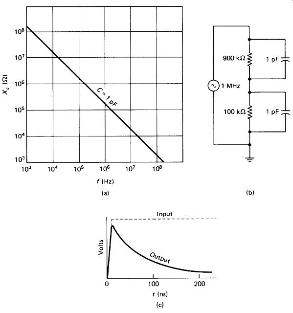
FIGURE 2-6 (a) The reactance of the typical 1 pF of stray capacitance across
a resistor drops to 159 k-Ohm at 1 MHz. (b) A high-resistance voltage divider
is completely swamped out by this reactance, (c) The shape of a square pulse
is distorted by the stray capacitive shunts.
Wirewound Resistors: Wirewound resistors designed exclusively for dc and low-frequency use may have an effective series inductance of 10 to 100 uH, enough to present significant reactance at high frequencies. However, nonreactive resistors using an Ayrton-Perry winding (two windings in opposite directions to cancel inductance) are readily available, and these display only a microhenry or so of residual inductance. Figure 2-7 shows the effects of frequency on composition, film, and wirewound resistors.
Wirewound resistors also have a shunt stray capacitance, typically 5 to 10 pF.
For low ohmic values (below 500 ohm) residual series inductance begins to increase the resistor's impedance at frequencies above a few MHz, but for higher values (1000-ohm and above) stray shunt capacitance lowers the impedance above a few megahertz. There is an optimum resistance range in the vicinity of 1 k-Ohm for which resistance is essentially constant to 10 or 20 MHz [see Fig. 2-7(c)].
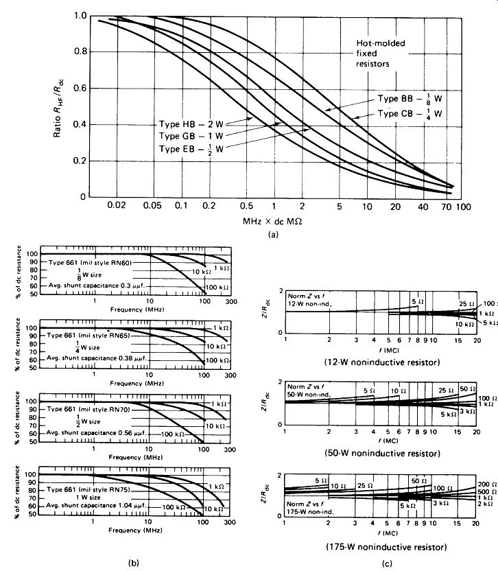
FIGURE 2-7 (a) Impedance versus frequency for composition resistors. (Courtesy
Allen-Bradley Co.) (b) Impedance versus frequency for metal-film resistors,
(c) Normalized impedance versus frequency for wirewound resistors. (Courtesy
Ohmite Manufacturing Co.)