3.1 FIXED-CAPACITOR BASICS
Energy Storage: A capacitor is formed whenever two conductive surfaces or plates are separated by an insulator (called the dielectric). If a potential difference exists between the surfaces, there will be an electric field in the dielectric representing a stored energy of:
(3-1)
... where W is the energy in joules (1 joule = 1 watt for 1 second), C the capacitance in farads, and V the potential difference in volts.
Charge Storage: The potential difference between the plates exists because of a difference in charge on them, and if a conductive path is provided between the plates, a charge (quantity of electrons) will flow between them to equalize their potentials. The amount of this stored charge is:
Q = CV (3-2)
...where Q is the charge in coulombs (1 coulomb= 1 ampere for 1 second), and C and V are in farads and volts as above.
Calculating Capacitance: The amount of stored energy and stored charge per volt is thus directly proportional to capacitance C, and this property is dependent on three factors:
1. C is directly proportional to plate area. Doubling the plate area doubles the capacitance, assuming, of course, that the same dielectric is maintained.
2. C is inversely proportional to plate spacing. Increasing the plate spacing weakens the field strength in the dielectric and thus reduces the amount of charge that can be held on the plates per volt of potential difference.
Doubling the plate spacing halves the capacitance.
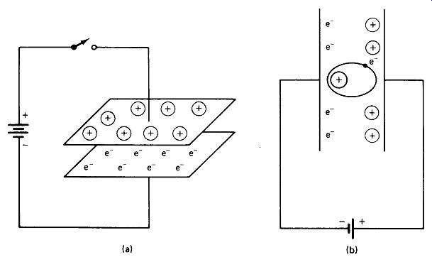
FIGURE 3-1 (a) Opposite charges are held on the plates of a capacitor by
mutual attraction, (b) The atoms.
In the dielectric become polarized (distorted) when the plates are charged.
3. C depends upon the dielectric material. As depicted in Fig. 3-1(b), the atoms of a dielectric material are distorted by the electric field, the electrons being pulled closer to the positive plate. This deformation represents additional stored energy in the dielectric, and the polarized atoms attract the charges on the plates, holding more charge per volt as polarization becomes more pronounced. Various dielectric materials are susceptible to polarization in different degrees, as indicated in the table of dielectric constants, Fig. 3-2. C is directly proportional to dielectric constant k.
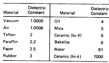
FIGURE 3-2 Typical values of dielectric constant k. Exact values depend
upon specific composition of material.
For a capacitor constructed of two parallel plates, the capacitance is given by
(3-3)
where C is in farads, k is the dielectric constant, A is the area between the plates in cm2 , and d is the plate spacing in centimeters.
Capacitor Construction: Capacitors are physically constructed as single plates, stacked plates, or rolled tubes, as illustrated in Fig. 3-3. The single-plate structure is common in the low-cost ceramic-disc capacitors, where values up to 1 uF can be obtained with high-dielectric-constant ceramic. Otherwise, this structure is limited to low capacitance values. Stacked plates are used with rigid dielectric materials such as mica and ceramic, whereas the more economical rolled tubular structure is used with flexible dielectrics such as paper and Mylar.
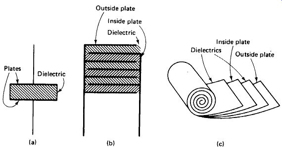
FIGURE 3-3 Capacitor construction: (a) single plate; (b) stacked plate;
(c) rolled tubular.
Notice that some capacitors are constructed so that the outside "plate" completely surrounds and en-shields the inside plate. This outside foil is then marked with a band or stripe on the case, and this lead should be connected to the circuit ground in noise-critical bypass applications. Figure 3-4 shows a selection of fixed-non-electrolytic-capacitor types.
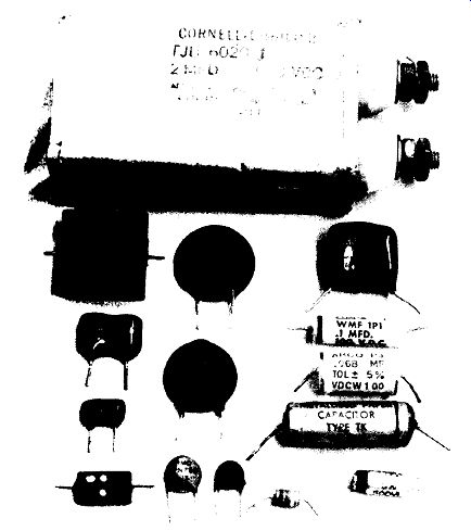
FIGURE 3-4 Representative types of fixed, non-electrolytic capacitors. Top:
a relatively small oil-filled type; left: four mica types ranging from 0.01
uF to 47 pF; center: high-k and medium-k ceramic discs, with temperature-compensating
and zero-temperature-coefficient ceramic discs below; right: dip-coated and
tubular Mylar, plastic tubular, metallized paper, tubular ceramic; bottom
right: poly styrene dielectric capacitor.
3.2 NON-IDEAL EFFECTS IN CAPACITORS
Real capacitors exhibit a number of nonideal effects which must be measured against cost in selecting a capacitor type for a given application. This section presents a brief catalog of the nonideal effects to be expected. The following sections of this section detail the types of capacitors available and their real-life characteristics. Figure 3-18 at the end of the section provides a tabular summary of this information.
DC Leakage: Ideally, a capacitor should be capable of holding a charge forever.
In practice, of course, current leakage through the dielectric and through the case material discharges the capacitor in time. For general-purpose capacitors of 0.1 uF and below, the case resistance generally limits the discharge time constant to a few seconds or less, decreasing for lower values. For high-value capacitors, however, the discharge time is primarily a function of the dielectric -material resistivity, as follows:
Polystyrene - 3 days
Paper ~ 3 h
Tantalum ~ 1 h
Ceramic (high k) - 5 min
Electrolytic ~ 10 s
Dielectric Loss: If an ac voltage is applied across a capacitor with a dielectric other than air or vacuum, the successive polarizations of the dielectric will cause some molecular friction and loss of energy. This loss is not easy to predict, as it varies with frequency and temperature and is different for each material.
Some materials exhibit severe loss peaks at certain frequencies. Polyvinyl chloride (PVC), which is widely used as an insulator, is unsuitable as a dielectric because of its loss characteristics, as shown in Fig. 3-5(a). Some typical effects of temperature on dielectric loss are shown in Fig. 3-5(b).
Frequency (Hz) Temperature (°C) (a) (b)
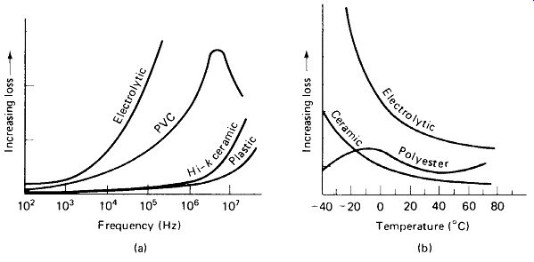
FIGURE 3-5 (a) Dielectric loss generally increases with frequency, but loss
peaks occur in some materials, (b) Loss varies with temperature, generally
increasing at low temperature for high-k materials.
Dissipation Factor: The cumulative effect of resistive shunt leakage, dielectric loss, and whatever series resistance may be present in the capacitor leads and plates is represented by the dissipation factor of the capacitor. This is defined as:
(3-4)
… where Rs is an equivalent series resistance (called ESR by the manufacturers) and Xc is the equivalent series reactance of the capacitor at the frequency in question.
For reasonably low values (10% or less), D is approximately equal to the power factor, which is the ratio of real power dissipated (heat loss) to apparent power (volt-amps) for the capacitor. The dissipation factor can be measured on most impedance bridges, and D or ESR is often specified in manufacturers' literature. It should be kept in mind that these values are valid only at the frequency and temperature specified, and will generally increase (sometimes drastically) at higher frequencies or lower temperatures.
Tolerance and Temperature Stability: Most capacitor types are manufactured to a tolerance of ± 10 or ±20% of the marked value at 25°C. However, certain types, such as aluminum electrolytics and high-Ac ceramics, are intended only to provide large amounts of capacitance in a small package at a low cost, and may have tolerances as wide as -20 and +100%. Most often, the manufacturers do not make a point of advertising these poor tolerances too loudly, so it is up to the technician to be aware of them. On the other hand, mica, polystyrene, low-k ceramic and Mylar capacitors are available (for a price) with tolerances as narrow as 1%.
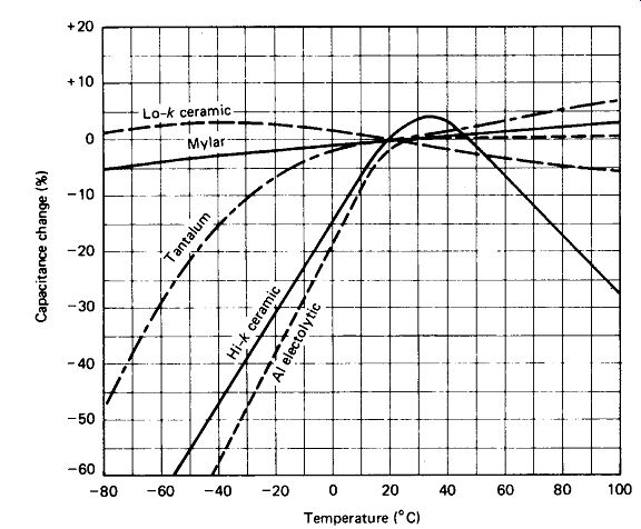
FIGURE 3-6 Capacitance changes with temperature vary markedly for different
dielectrics.
General statements about the effects of temperature on capacitance are quite difficult to make, since the effect varies, not only between different dielectrics, but also between different versions of essentially the same dielectric. Figure 3-6 gives a rough idea of the effect to be expected for a few common dielectrics. Note in particular the drastic drop in capacitance at low temperatures for aluminum electrolytic and high-/c ceramic capacitors.
Lead Inductance and Resonance: As noted in Section 1, hookup wire possesses a stray inductance of approximately 0.04 uH/cm, so a 0.1-uF capacitor with two 2.5-cm leads is really 0.1 uF in series with 0.2 uH, a combination which resonates at slightly above 1 MHz, with XL and Xc of about 1.4 ohm. Above this resonant frequency, the reactance of the "capacitor" is actually inductive, rising to about 14 ohm at 10 MHz, 140 ohm at 100 MHz, and so on.
The table of Fig. 3-7(a) shows the measured resonant frequencies of various capacitors, and Fig. 3-7(b) shows the measured impedance of two of them as a function of frequency.
The reactance of the 0.01-uF "capacitor" in Fig. 3-7(a) is definitely inductive above 7 MHz, and this fact is demonstrated with surprising effects when a 470-pF capacitor is placed in parallel with it. A parallel resonance occurs at 23 MHz, resulting in a total impedance rise to 36 ohm, four times higher than the impedance of either capacitor alone. This parallel-resonance effect should be kept in mind, as it is common practice to use separate audio and RF bypass capacitors in parallel in some circuits. The effect is much less pronounced if the larger capacitor is in the microfarad range, however. Here the reactance at resonance is likely to be a fraction of an ohm, and the total parallel-resonant impedance will not rise above an ohm or two.
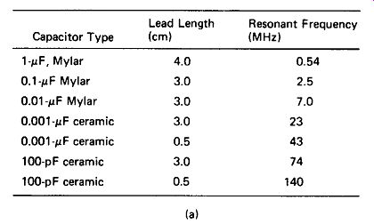
FIGURE 3-7 (a) Real capacitors series resonate with the stray inductance
of their leads and plates. Above fr, reactance is inductive and increases.
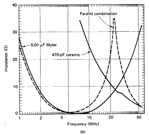
FIGURE 3-7 (b) Parallel resonance of a low- and high-value capacitor produces
an impedance rise.
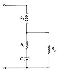
FIGURE 3-8 Equivalent circuit for a real capacitor. L. is the lead and plate
inductance, Rs represents dielectric loss and lead resistance, and Ftp is
the dc leakage through the dielectric and case.
Real Capacitor Equivalent Circuit: The real behavior of a capacitor is represented in Fig. 3-8. Series inductance Ls and dielectric loss Rs become important at high frequencies, while leakage R is important for dc storage over long time periods.
3.3 MICA- AND CERAMIC-DIELECTRIC CAPACITORS
Mica Capacitors: Mica is a mineral that occurs naturally in thin, flat sheets. As a dielectric material it is quite temperature-stable and has a low dissipation factor, even at high frequencies. It has been used since the early days of radio in stacked-plate capacitors up to about 0.01 uF, although its popularity is finally giving way to ceramic and plastic-film types. Constructed as alternate sheets of metal foil and mica, stacked, bound, and encapsulated in plastic, these capacitors achieve a temperature stability of about ±300 ppm/° C.
The silver-mica variety, constructed by depositing a thin silver layer directly on the mica sheets, provides a temperature coefficient not greater than ± 100 ppm/°C and are often called zero-temperature-coefficient mica capacitors. Both types have dissipation factors of 0.1% or lower. They are available in tolerances ranging from ±20% to ± 1%.
Ceramic Capacitors: Ceramics are a class of mineral compositions which are molded and then fired at high temperature. Ceramic capacitors are occasionally seen in the form of a hollow cylinder, but more often as a disc, as shown in Fig. 3-4, or as a block containing a stack of plates, as shown in Fig. 3-3(b). They are potentially the most confusing things, because they all appear so similar, yet they have widely different properties. The discs invariably have a diameter of between 0.5 and 2 cm, and a single conductive plate on either side of the dielectric which ranges in thickness not much beyond 0.2 to 1 mm. Yet their capacitance values range from 1 pF to 1 uF, a span of six orders of magnitude. This is possible because ceramics can be produced with dielectric constants from 5 to 10,000 or more. However, the quality of the dielectric is severely reduced as its dielectric constant is increased.
Although the range is actually continuous, it might be helpful to think of ceramic capacitors as being divided into two classifications -- low-Ac and high-Ac dielectric.
Low-Ac Ceramics include the values to approximately 0.01 uF in disc and 0.2 uF in monolithic (stacked plate) form. Their dissipation factor at 25 ° C is typically less than 1% at 1 kHz, rising to perhaps 10% at 10 MHz for the larger values. Insulation resistance exceeds 10 G-ohm. Tolerances of ± 10 and ±20% and capacitance changes of ±2% from -20 to +85° C are common.
High-Ac Ceramics include values from 0.01 to 1 uF in disc and from 0.2 to 6.8 uF in monolithic form. Dissipation factors at 25° C are typically 2 to 5% at 1 kHz, rising to 50% at 1 MHz for the larger values. Tolerances of ± 10% are available in monolithic ceramic, but for the larger value discs -20, +80% is common.
Capacitance changes of -50% and dissipation factor increases of 500% may be encountered at - 20°C in the larger value discs. Insulation resistance also varies drastically, from more than 1 G ohm to less than 10 k-Ohm depending upon type, value, and voltage rating. In general the high-value discs have the poorest characteristics and the low-value monolithics have the best characteristics. A thorough check of the capacitor's specifications is recommended when high-Ac ceramics are to be used in critical applications. Capacitors for which no tolerance or temperature specifications are given should be regarded with suspicion.
High-Ac ceramic capacitors may exhibit a decrease in capacitance with age on the order of - 1% after 1 h, -2% after 10 h, -3% after 100 h, up to -5% at 10,000 h of operation.
EIA Standards for Ceramic Capacitors: In an attempt to bring some order to the confusion over ceramic-capacitor properties, the Electronics Industries Association (EIA) has devised a system of standard ratings, which is reproduced in Fig. 3-9. As an example, a capacitor marked 680 K Y5E would have a capacitance of 680 pF ± 10%, with a change of not more than ±4.7% over the temperature range -30 to + 85°C.
Tolerance +100-0%, also known as GMV (guaranteed minimum value)
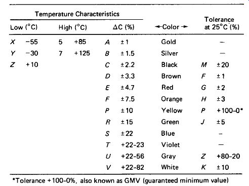
FIGURE 3-9 EIA standard markings for ceramic capacitors. Example: 0.47M,
Y5F indicates 0.47 pF ± 20%, with maximum ± 7.5% change from -30to +85°C.
Temperature-Compensating Ceramics: By controlling the composition of the ceramic dielectric, it is possible to produce capacitors whose value varies in a predictable and fairly linear manner with temperature (from +100 to about - 5000 ppm/° C.) Note that -5000 ppm/°C amounts to a -10% change for a 20°C temperature rise. The table in Fig. 3-10 lists the EIA codes for the standard temperature coefficients available. The most common among these are the zero temperature-coefficient NPO types, which are often used in critical tuning and filtering circuits, and the N750 ( - 750 ppm/°C), which is used, often in parallel with NPO or Variable types, to offset the positive temperature coefficients of coils in rf tuned circuits. With proper implementation of temperature-compensating capacitors, an rf oscillator can be produced whose frequency drift with temperature is an order of magnitude less than that of an uncompensated oscillator.
NPO ceramics are available from 1 pF to about 0.18 uF in voltage ratings of 50 to 1000 V. N750 types are available to about 1000 pF. These types have dissipation factors of 0.1% or less at 1 MHz and are available in tolerances from ± 20% to ± 5%. Ceramics with temperature coefficients up to N4700 have slightly higher dissipation factors (0.4% typical).
FIGURE 3-10 EIA letter and color codes for temperature-compensating capacitors, with typical available tolerances on TC. Example: U2 or violet code Indicates nominal negative 750 ppm/°C capacitance change, but may be actually - 690 to -810 ppm/° C.
3.4 PAPER AND PLASTIC-FILM CAPACITORS
Paper Capacitors: Paper-dielectric capacitors are constructed as a cylindrical roll of metal foil and paper, as shown in Fig. 3-3(c). Generally, two papers are used in each layer to minimize the effects of carbon spots that appear in the paper. The dielectric is soaked in various waxes or oils, called impregnates, to stabilize the dielectric constant and prevent the intrusion of moisture. Values from 0.001 to 1 uF are commonly available, with voltage ratings from 50 to 1500 V and tolerances of ± 10% or ±20%. Insulation resistance is typically above 10 G-ohm, and the dissipation factor is in the vicinity of 1% at 25° C and 1 kHz.
Metallized Paper: Methods have been devised for depositing a very thin metal coating directly on the paper dielectric. This has the advantage of reducing the size and weight of the capacitor by about 30%. Metallized capacitors are also self-healing in many cases; a spark across the dielectric will evaporate the metal film at the defect point, leaving no conductive short circuit. Metallized paper capacitors have characteristics similar to standard paper units, except that their insulation resistance is about an order of magnitude lower.
Plastic-Film Capacitors: Paper dielectrics have been largely replaced in the last two decades by a variety of plastic films: Mylar, metallized Mylar, polyester, polycarbonate, and polystyrene. Mylar and polyester capacitors typically have power factors, insulation resistances, and tolerances which are all a factor of 2 better than their paper counterparts. Polystyrene capacitors are considerably better still, with dissipation factors as low as 0.02%, insulation resistance in excess of 1000 G-ohm, and tolerances of ±1%.
Oil-filled Paper Capacitors: These are the "brutes" of the capacitor world, commonly reaching sizes of 10 X 10 X 15 cm and prices of $50 each. They consist of a steel case containing a paper-dielectric capacitor immersed in liquid oil and hermetically sealed. Their use is dictated when capacitances above 1 uF at voltages above 500 V are required, or when dissipation factor, tolerance, or reliability requirements eliminate the low-cost electrolytic capacitor as an option. Their dissipation factor and insulation resistance are comparable to those of standard paper capacitors.
3.5 ELECTROLYTIC CAPACITORS
Construction: The electrolytic capacitor is formed as a cylindrical roll of aluminum foil and paper layers, much like the paper capacitor. However, the paper is impregnated, not with a dielectric, but with a conductive paste called the electrolyte. The dielectric is an oxide of this electrolyte which forms in a very thin layer against the foil when voltage is applied across the capacitor. This forming process may take several minutes for a new capacitor, during which time the capacitor will conduct current and may become noticeably warm. Electrolytics left uncharged for several months may again require a short re-forming period, during which time they are dc-conductive. Their great advantage is their high capacitance per unit volume-electrolytics can typically squeeze 10 times the capacitance into a given case size as a paper type of the same voltage rating, and at low voltages the advantage swells to a factor of 100 or more.
Tantalum electrolytics have become popular for military and industrial use in recent years. They offer the same advantage as aluminum electrolytics, and feature better tolerance, greater reliability, and higher cost, all by about a factor of 4.
Tantalums can be formed, not only as a roll, but also as a porous cylindrical slug of tantalum (anode) with an electrolyte filling the pores and conductive to the case (cathode). Figure 3-11 shows a representative selection of electrolytic capacitors.
Polarity: Most electrolytic capacitors are polar and care must be taken to ensure that significant reverse voltage is never applied across them. Where the markings are obscure, the metal case is almost always the negative lead. Momentary reverse voltage will not usually destroy the capacitor, but may require its re-forming.
Sustained large reverse voltages will cause current conduction, overheating, and, in the larger sizes, actual explosion of the capacitor, sometimes quite violently.
Non-polar electrolytics are available, although they are not nearly so popular as the polar type. The letters NP after the voltage rating designate a non-polar electrolytic. Regular polar electrolytic capacitors can be used safely with reverse voltages of 1 or 2 V, but the leakage current goes up rapidly for reverse voltages much beyond this. For higher voltages, two polar electrolytics can be connected in series back to back to provide a single non-polar unit.
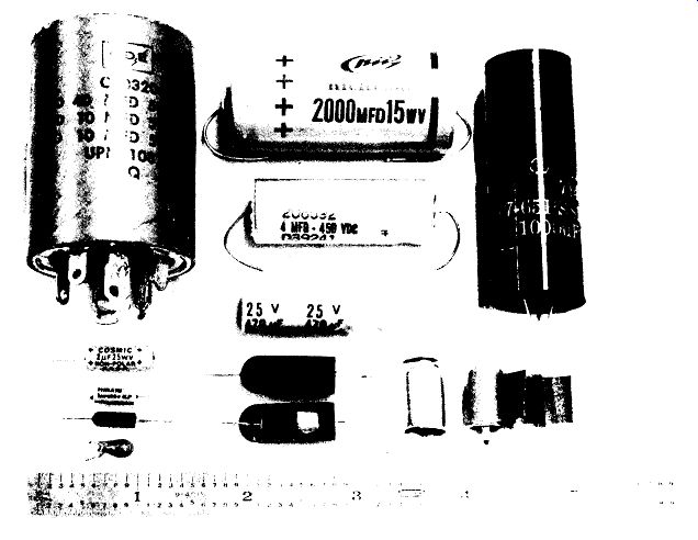
FIGURE 3-11 Representative electrolytic capacitors. Top left: three-section
FP (flat plate) chassis-mount type; top center: low- and high-voltage axial-lead
types, with radial-lead (also called vertical or PC-mount) types below and
at right; bottom left: two non-polar electrolytics with two small tantalums
beneath; bottom center .' tantalum slug type with broken-away unit showing
interior; bottom right ; case and foil-paper wrappings from an aluminum electrolytic.
Voltage Rating: Aluminum and tantalum-foil electrolytics are limited to voltage ratings of 550 V or less by the nature of the dielectric. Slug-type tantalums are generally confined to applications requiring a rating of 100 V or less. Electrolytics are generally rated for continuous use at their working voltage, and for short-term (such as turn-on or warm-up) use at their surge voltage. Surge rating is typically 130% of working rating (e.g., 8 MFD, 150 WVDC, 200 V SURGE). Where higher-voltage ratings are required, two or more electrolytics may be placed in series and their voltage ratings added (their capacitance being halved, of course). It is advisable in this case to place equalizing resistors across each capacitor, as shown in Fig. 3-12, to ensure that the dc voltage divides equally across each unit.
The resistors should be calculated to draw 10 to 100 times the expected leakage current of the capacitors (see below), but a value of 100 k-Ohm is common.
FIGURE 3-12 Equalizing resistors are used across series electrolytics to
ensure equal division of high dc voltages.
Nonpolar electrolytics intended for motor-starting applications are often rated for rms ac voltage. The peak-conversion factor of 1.41 can be applied to convert this rating to dc voltage.
Reliability: Electrolytic capacitors have a relatively high failure rate, so their use is avoided in high-reliability designs, except where their high capacitance-to-size ratio makes them the only choice. The best tantalums have expected failure rates of 0.1% per 1000 h (compared to 0.01 or 0.001% for typical carbon resistors), and low-cost aluminum electrolytics are much worse. In view of this, the wise designer will choose electrolytics with a working-voltage rating 25 to 50% higher than the intended application and will take steps to keep the operating temperature of the capacitors as low as possible.
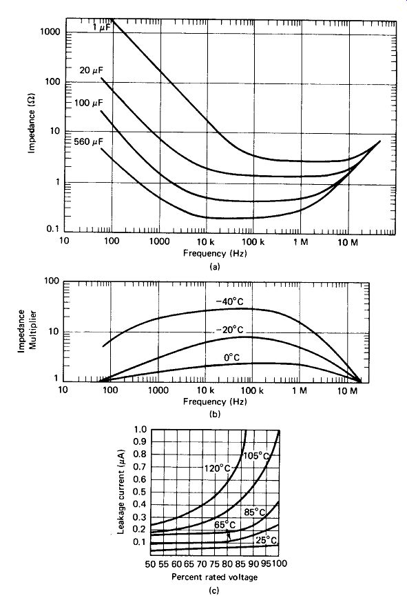
FIGURE 3-13 (a) Impedance versus frequency for typical aluminum electrolytics
at 25 "C. (b) Correction factors, showing effective capacitance drop
at low temperatures, (c) Leakage current in an electrolytic Increases rapidly
above rated voltage, resulting in heat generation. Higher temperatures further
Increase leakage, so the heat generation can quickly avalanche. (Courtesy
General Electric Company.)
Tolerance and Temperature Effects: Aluminum electrolytics are marketed with tolerances between - 10 +50% and -20 +100%. They are intended for filtering, coupling, and bypassing and not for timing and resonance applications. Tantalum electrolytics can be purchased with tolerances as good as ± 10%, making them suitable for many applications where aluminum will not do. It should be noted that all these tolerances are specified at +25° C.
The capacitance of aluminum electrolytics will typically drop by 20% at - 20° C and by 50% at - 40°C. Tantalum generally fares somewhat better, dropping by typically 20% at – 40 ° C and 50% at -55°C. Capacitance change at high temperatures is positive, typically +10% at 85°C for aluminum and +5% at 125°C for tantalum. Figure 3-13(a) and (b) documents this.
Leakage Current and Dissipation Factor: Electrolytic capacitors generally exhibit dc leakage currents which amount to a shunt resistance between 1 MQ and 10 MB at 25° C. This leakage resistance is relatively constant for various voltage ratings and for values up to 100 uF, but begins to drop inversely with capacitance values above 100 uF. Figure 3-13(c) shows how this leakage increases with voltage and ...
[p 48 missing]
Operating Life: Electrolytic capacitors require a moist electrolyte, and if this is allowed to dry out, the dissipation factors will increase and the capacitance will decrease, eventually to the point of failure. At 25°C, an electrolytic capacitor with a simple rubber seal may be expected to last for 10 to 20 years, but, as shown by Fig. 3-14, the life at 85°C may be reduced to 1 year. Operation at low atmospheric pressures further accelerates dry-out. Improved seals and encapsulation increase dry-out time, the ultimate being the hermetically sealed unit of Fig. 3-15, which anticipates a life in excess of 50 years in a vacuum at 125° C.
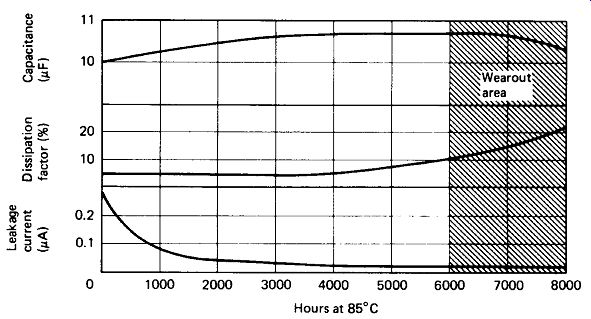
FIGURE 3-14 Expected load life at 85°C. The electrolyte drys out with age.
giving the typical electrolytic capacitor a limited life span. High temperature greatly reduces life expectancy. (Courtesy General Electric Company.) Residual Charge: Figure 3-1 shows how the dielectric is polarized by the electric field between the plates of a charged capacitor.
In an electrolytic, the dielectric requires a considerable period of time (0.1 to 10 s) to depolarize after discharge, and a residual charge of perhaps 10% can be expected to appear after a brief discharge, as shown in Fig. 3-16. A second discharge, or a very long first discharge, will be required to establish true zero voltage across a charged electrolytic.
Paper, Mylar, and ceramic capacitors will recharge in this manner to only about 0.
1% of original charge, so the problem is generally negligible in their case.
3.6 VARIABLE CAPACITORS
Variable Capacitors: These capacitors are most commonly used for tuning radio-frequency circuits. They are available with maximum capacitance from about 5 to 500 pF, and in voltage ratings from 300 to several thousand volts.
FIGURE 3-15 (a) MIL-STO designations for electrolytic capacitors. (b) Typical
rubber seal to retard drying of electrolytic (c) Hermetic seal which greatly
Increases life span. (Courtesy General Electric Company.)
Minimum capacitance is generally to of the maximum value. Their structure, illustrated … in Fig. 3-17, consists of a number of half-circle-shaped rotor plates (1 to 20, depending on capacitance) which are turned on a shaft to mesh in or out of a number of stator plates. The rotor plates are generally connected to a U-shaped metal support, while the stator plates remain insulated. High-quality variables use ball bearings at two points on the shaft and ceramic insulation. The mechanical rigidity of the plates has much to do with the ultimate stability of a radio-frequency tuning system, and thick, stout plates should be sought for critical applications.
60
FIGURE 3-16 A charged electrolytic that is discharged to zero for a brief period will recharge to as much as 10% of its initial voltage due to polarization in the dielectric.
If the shaft is placed at the center of the plate, a straight-line curve of capacitance versus shaft rotation is obtained. However, if the shaft is offset to one side, the curve can be made nearly linear for frequency versus shaft rotation, which is more desirable for radio-tuning applications.
Ganged Capacitors: Often, several circuits must be tuned simultaneously to the same frequency or to related frequencies. Variable capacitors are available with two, three, or four sections ganged together on the same shaft, as shown in Fig.3.17. The outside plate is often split in four or five places, with the intent that it be bent out or in to make that section track with the other sections, or with the tuning dial. The rotors of all the sections are already electrically connected, and often the stators are also paralleled to produce a high-capacitance variable.
Butterfly capacitors, illustrated in Fig. 3.17, provide a symmetrically balanced two-gang variable which covers its range in \ turn. The differential variable capacitor is a two-gang unit in which one section increases as the other decreases, the sum being essentially constant.
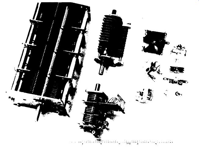
FIGURE 3-17 Representative variable capacitors. Left: four-gang 500 pF/section;
center: single-section 80-pF " transmitting" type with three-gang
FM tuning capacitor below (note RF coils and piston trimmer at very bottom);
right: 12 pF/section butterfly, 16-pF air trimmer, and two-section plastic-dielectric
tuning capacitor from a pocket radio at bottom; far right: three mica-dielectric
compression trimmers (750, 500, and 100 pF), with two views of a 70-pF ceramic
trimmer below.
Trimmer and Padder Capacitors: Trimmer capacitors are variables that are in tended to be adjusted with a screwdriver rather than a dial. They are available as air/plate units, piston type, ceramic, and compression types, all of which are illustrated in Fig. 3-17. Compression trimmers with capacitance from 500 to 5000 pF are generally called padders. The following table and Fig. 3-18 lists their relative advantages.

FIGURE 3-18 Summary of real properties of fixed capacitors.