21.1 AN APPROACH TO TROUBLESHOOTING
We may as well put the main point right up front where it will be noticed: Effective troubleshooting is a matter of checking out your expectations about a circuit. The expectation may be general such as: " The pilot light should come on when I pull the ON button," or it may be specific, such as: "If I short pin 2 of the 555 IC to pin 1, pin 3 should go high for about 1 ms." You may not be able to form detailed expectations about every part of the circuit, but neither should you be completely without expectations at this point in your studies. This section and the ones following will help you to recall and organize them in a logical way.
You will go on checking the circuit’s behavior against your expectations, one by one, until you find one that doesn't match. At that point there are only three possibilities:
1. That part of the circuit is malfunctioning, 2. Your expectation was in error, or 3. Your measurement was in error.
In the first case you will have narrowed the problem down to a small area. In the second case, you will have learned something about circuit behavior which will be of use to you later. In the third case, you will have learned something about measurement technique, or will have discovered a faulty piece of gear. In any case it will be profitable--if you stop long enough to take advantage of the opportunity.
Tremendous mental discipline is often necessary to avoid wasting this opportunity. The temptation is always strong to say, "I don't know if this is the right reading or not," and pass on to an equally fruitless measurement in the next stage.
To avoid such aimless troubleshooting it is a good idea to jot down your expectation or speak it aloud before you take the measurement. (Contrary to malicious rumors, this is the reason why good technicians are often heard talking to themselves.) If you don't have a firm expectation of what you should see, there is absolutely no point in taking the reading. You won't know what you're seeing anyway, so it's just a waste of time. You would be better advised to cast about for a more clearly held expectation to check out, or when that avenue is exhausted, to look into a book or manual to obtain a better understanding of the circuit in order to form more expectations about its operation.
It bears repeating that once you find a discrepancy between your expectation and the circuit's performance, you must stop at that point in the circuit until you resolve the conflict. If you expect a gain of 20 in the first audio-amplifier stage and you measure a gain of 2, don't check anything in the audio output stage. Don't take any readings in the power supply. Stay with the first audio stage until you find the trouble. You may find an open capacitor or you may find that you forgot about the x 10 probe on the second channel of your scope, but stay with it until your expectation and your measurement match.
Fooling Yourself: There is an insidious tendency in most of us to "read what we need" instead of what our instruments are actually indicating. Our minds are pre-loaded with an expectation that we want to see confirmed, and as soon as the " right " number pops up on the scope or meter, we jump for it without taking the time to see that the instrument is really set up properly. Here are some common measurement errors:
. Forgetting X 10 probes
. Failing to check zero and calibrate controls
. Substituting an rms measure for a peak-to-peak expectation
. Measuring line noise picked up on an open probe and calling it signal
. Failing to notice that the meter resistance or capacitance is loading the circuit
. Attempting to measure ac voltages above the maximum rated frequency of the instrument
Clearing the mind of expectations is not the answer to this problem, because expectations are basic to troubleshooting. Careful and methodical technique, experience with the instruments, and a constant skepticism about your readings are the best defense.
21.2 SOURCES OF EXPECTATIONS
Experience: Rapid troubleshooting is almost always the result of experience, not technical competency. Many of us have seen the TV man march into the room, sniff the air, pop the back off the set, whip out his soldering gun, change C 437, and put the set back on the air in five minutes. It’s easy to be impressed by this sort of thing and to want to emulate it. What the TV man doesn’t tell you is that he’s changed C 437 nineteen times in the last week and keeps a handful in his pocket so he won’t have to walk back to the truck. The head bench tech spent three days on it the first time somebody brought a set in with that problem.
There's nothing wrong with this kind of troubleshooting-it is very effective with mass-produced items. Industrial troubleshooting is seldom this repetitive, and we must look to other sources than experience for our expectations.
Visual Checks lead directly to the trouble often enough to make this the first avenue of attack, even before the voltmeter is brought out. Fuse elements can be inspected and transformer hum can be telegraphed up a large screwdriver to the ear to see if power is reaching the supply. Resistors may have a black charred ring or may be puffed up and cracked in the center. Switch contacts may be corroded or bent. Bare wires may be touching, or a loose nut, wire end, or piece of solder may have fallen and become wedged between two wires or terminals. Printed-circuit tracks may be broken from overstress or shorted by corrosion from water, battery paste, or other foreign material.
Some of these "problems" may actually be only symptoms of a deeper problem. Fuses, resistors, and transformers, for example, seldom fail unless they are overstressed-by a leaky filter capacitor perhaps. When replacing a 1-A fuse which blew for no apparent reason, it would be a good idea to measure the line current (with the fuse out and an ammeter across the fuse holder terminals) to see if the new fuse is also being stressed near its limit. Similarly, the voltage across a newly replaced resistor should be measured and the power calculated to see if it is necessary to look further for the real source of the trouble.
General Expectations can be checked out without a schematic or detailed circuit tracing.
. Silicon power diodes should drop no more than 1.1 V in the forward direction, giving an indication of no more than 0.5 V on the test fixture of Fig. 21-1 (a).
. Large electrolytic capacitors (100 uF or more) should have at least half the rated voltage across them unless the designer gave no thought to economy.
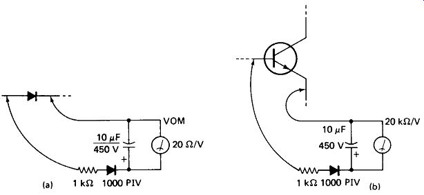
FIGURE 21-1 (a) A conducting diode should read between 0.1 and 0.5 V on the
VOM with this test circuit. Less may mean a shorted diode. More means the diode
Is open. Start on a high-voltage VOM scale, (b) Transistor forward voltage
should produce not more than 0.5 V on the VOM.
Transistors should have a forward base-emitter drop of no more than 1.1 V, giving an indication of no more than 0.5 V in the test fixture of Fig. 21-1(b).
Transistors, even when operated as saturated switches, should show at least a few tens of millivolts from collector to emitter. Absolutely zero volts may mean that the transistor is shorted.
Power resistors and transistors should get at least moderately warm: if not at idle, then under full signal. Power components would not have been used if cheaper milliwatt components would suffice.
Generally, any component that boils a drop of water is under strong suspicion.
Gentle pressure with a plastic probe on components, wire bundles, and circuit boards should not cause abrupt changes in instrument operation.
Common IC types and families should have dc supply voltage on their Vcc pins, as shown in Fig. 21-2.
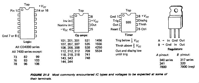
Fig. 21-2.
The Schematic Diagram provides the most valuable and complete source of expectations about the operation of the circuits in an instrument. Often the diagram includes expected scope waveforms and voltmeter readings at specified points in the circuit. These are helpful, but they should not be used blindly. The function of each part of the circuit should be determined first (i.e., preamp, oscillator, Schmitt trigger, etc.) so the waveforms and voltages can be fit into a meaningful pattern.
Service manuals may include block diagrams, circuit descriptions, trouble-shooting procedures, and resistance charts. These should be used in conjunction with the schematic diagram, not in place of it.
21.3 FAILURE PROBABILITIES
Certain types of components are observed to cause equipment failure more often than others, and a knowledge of this hierarchy is useful in troubleshooting. The following list, gleaned from experience, proceeds from the most likely to the least likely cause of the problem:
. Operator error
. Cables and connectors external to the instrument
. Switches and relays
. Power semiconductors
. Cables and connectors within the instrument
. Soldering and circuit-board faults
. Small signal semiconductors
. Electrolytic capacitors
. Power transformers and inductors
. Power resistors
. Variable resistors
. Ceramic capacitors
. Mylar and paper capacitors
. Low power resistors
. Mica capacitors
. Low power inductors
A glance at the top of the list will suggest several "quick-fix" approaches to try.
1. More service calls really are due to operators who don't know how to use the instrument than to any of the other causes listed. Make sure that you know how to use it and how to bring it back from a completely misadjusted condition. Find out about all the seldom-used concentric control knobs, back-panel controls, shorting plugs, and so on. Read the operator's manual-ignominious as that may be. You could find something important hidden among the gobbledygook.
2. External wires and connectors are vulnerable to abuse and are often a source of trouble. Merely examining them or flexing them while the unit is operating will often show up a short or open.
3. Switches and relays often become corroded, pitted or lose contact pressure.
Slow operation of the switch handle, or a gentle pressure on the relay armature, may point up an intermittent contact. A shot of contact cleaner may also help.
4. Power transistors and diodes fail frequently enough to make it profitable to disconnect the emitter and base leads (or either end of a diode) so that the junctions can be checked with an ohmmeter.
21.4 HOW TO TROUBLESHOOT
If none of your general expectations about the instrument leads to the defect, you will have to organize your resources for a technical attack on the problem. It will pay to follow some such procedure as the following.
Define the Problem: By this we mean something a little more incisive than the vague statement " It don't work." Of a digital multimeter we might say, "Ohms scales progressively more inaccurate on higher ranges, to - 50% error on 10-MB range. Dc and ac volts and amps OK. "
Of a TV receiver we might say, "Picture slants and floats sideways. Horizontal hold sensitive and unable to stabilize. Vertical hold, audio, picture definition OK."
The first benefit of making such a statement is that is concentrates your attention on the defective area. Most electronic instruments are too extensive to be taken in at one bite, so "divide and conquer" must be the rule. The second benefit is that it gives you something intelligent to say when discussing the problem with the factory rep, boss, or senior tech, who might be able to point you toward the solution if you define the problem clearly enough.
Get the Schematic: Troubleshooting without a schematic is like working a crossword puzzle blindfolded. Call the manufacturer, the nearest electronics supplier, the library, or whomever you must, but get a schematic. Without it the situation is all but hopeless and your time is being wasted, so take whatever time is needed to secure it. And when you are through put a copy in a plastic envelope inside the instrument case for the next poor fellow--he may be you.
Clear the Workbench: Signal generator on the left, instrument and schematic in the center, oscilloscope and voltmeter on the right is a good way to organize it.
Turn on the soldering pencil and test equipment and let them run so that they will be warmed up when you need them. Have a few parts trays available to keep screws and other small items together as you disassemble the instrument.
Proceed with voltage checks using the oscilloscope in the dc-coupled mode in the following sequence:
. Power supply# 1: dc output and ripple; power supply#2: and so on
* Input to stage 1, output; input to stage 2, output; and so on
If you don’t know what supply voltage to expect, go back and analyze the circuit to determine what it should be. If you are unable to do this, you , re probably in over your head and should go back to a study of power-supply circuits. If you don’t understand it, there is little chance that you're going to be able to fix it.
If there is no input to stage 1, use your signal generator to inject one. If you don't know what frequency or amplitude to inject you probably don't understand the circuit well enough to be troubleshooting it, and it's back to the books again.
This is not running away from the problem. This is confronting the problem-the real problem-of lack of understanding.
Keep a Record of your expectations and measurements. A loose-leaf binder with paper divided vertically down the center is ideal. Date each entry, indicate the instrument by serial number, and when you finally locate the trouble, don’t forget in your elation to indicate what it was in the notebook. You or your successor may see that instrument again in two years, and a minute spent now might save an hour then.
And in the name of mercy, if you have to remove a transformer or a connector with two dozen leads on it, keep a very meticulous sketch of how the wires are to be reconnected.
Don’t Redesign the Instrument: You may find in the course of your investigations that if R 542, which is marked as 820 ohm on the schematic and appears as 820 ohm in the instrument, is changed to 560 ohm, the instrument suddenly begins to work. This is an interesting bit of information, but it does not justify popping in a 560-ohm resistor and closing the cabinet! If it worked once with 820 ohm, it should work now with 820 ohm. Obviously, there is some other problem lurking in there which the change to 560 is able to cover up. Maybe it is a leaky capacitor, or a drying-up electrolytic, or a transistor whose beta is changing, or corrosion on the circuit board, any of which is likely to get worse-so changing R 542 to 560 ohm would be only a temporary solution anyway.
Watch Out--It May Fry Again: After replacing the guilty component, turn the power on briefly, watching for smoke or other signs of malfunction. Next keep it under power for at least five minutes while observing its operation to be sure that heat buildup is not working to cause another failure. Finally, let it cook in an out-of-the way corner for several hours if possible. The failure of one component often overstresses several others, and it is wise to give all latent problems a chance to show themselves before returning the instrument to service.
21.5 SIGNAL TRACING
Divide and conquer is the rule in troubleshooting. Most often we can isolate the fault to one area of the instrument just by the symptoms exhibited at the front panel. Let's take an oscilloscope as an example that every technician will be familiar with.
If there is no light on the screen at all, we would first check the power supplies (there may be four or five). If darkening the room shows a light at the top of the screen which moves with the horizontal-position control but not with the vertical control, we will confine further testing to the vertical amplifier. If we can produce a horizontal line with an external horizontal input but not with the internal sweep, we start troubleshooting in the sweep generator. If we get sweeps but they won’t lock to the displayed signal, we start digging into the sweep-trigger circuits.
Always obtain as much information as you can from the front panel before opening up the instrument. If the scope won't lock in on an internal sine wave, what about a square wave? What about external trigger and line trigger, auto trigger and driven mode, different settings of the range and variable controls? Board Swapping: Many instruments are designed with plug-in circuit boards, each board containing a distinct function. A serviceman armed with a caddy of spare boards and a rudimentary knowledge of the instrument’s function can be quite effective in such a situation without expensive test equipment or a detailed knowledge of electronic circuits. Keeping the necessary stock of spare boards is practical only where service work is confined to a few types of instruments, however, and after a few months under these conditions a good serviceman will gain enough experience with the foibles of the equipment to troubleshoot it to the component level anyway.
Instruments often contain two or more identical plug-in boards. If swapping them causes the trouble to move from one area of the instrument to another, one of these boards obviously bears the problem. This technique may be invalid if the boards contain adjustable components. In any case, the boards should be returned to their original positions to preserve the original alignment of the instrument.
ICs may also be swapped in this way to locate problems where an instrument contains several odd types for which no replacement is in stock. Remember, though, that if an IC went bad, the circuit may have overstressed it, so it is best to apply power only briefly when testing the swap. A finger tip on the IC will let you know if it is overheating.
Checking Inputs and Outputs: Let us say that you have a malfunctioning instrument on the bench. Symptoms and front-panel response indicate that the problem lies in an output dc amplifier or preamplifier stage. Your memory produces no recollection of a previous similar problem, visual inspection reveals no obvious damage, and a quick check of the most failure-prone components in the defective area shows them all to be good. You have the schematic and your oscilloscope is warmed up. Now at last you are about to see the fruit of the labor you invested in studying electronic circuits.
Electronic systems are composed of functional blocks: circuits which receive one or several input signals and produce one or several output signals. Trouble shooting at this stage consists of:
1. Recognizing the functional blocks in the problem area (i.e., generating expectations of what the input and output signals should be)
2. Checking out these expectations with the oscilloscope Absence of an input signal can be caused either by a defective driving stage or by an input short circuit, as illustrated in Fig. 21-3 (a) and (b), respectively.
Absence of an output signal can be caused by a defective stage or by a shorted load. The same two figures serve to illustrate this concept. Determining whether the fault lies in the driving or driven stage may require breaking the path between them. If this causes the driver output to suddenly reappear, the driven stage was apparently shorting the output. To verify this, a signal generator can be used to drive the opened input line. If the signal generator too is shorted, the diagnosis is confirmed.
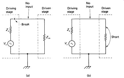
FIGURE 21-3 Absence of an input signal may be due to defective driving
stage (a) or shorted driven stage (b). Breaking the line between them will
show which is the case.
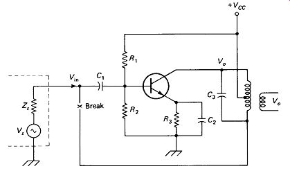
FIGURE 21-4 If the feedback path of an oscillator Is broken and a signal Is
injected at the proper frequency, the signal will be amplified.
Oscillators, whose output feeds the input, are a little tougher. However, if the feedback path can be broken and a signal of the proper frequency injected, as in Fig. 21-4, the basic amplifier function can be tested.
Recognizing the Functional Blocks is not always easy; there are at least 50 common ones and designers seem to delight in coming up with new ones and disguising the old ones. However, there is no point in trying to troubleshoot a circuit if we don't know what the input signal should look like, or if we don’t know what kind of an output signal it should produce. We could measure the input and output signals, but we wouldn’t know if they were right or wrong. This is why we study electronic circuits: to gain an ability to recognize the functional-block circuits and to have an expectation of what the input and output signals should be.
A list of common functional blocks is given in Table 21-1 as a kind of study guide. For each circuit listed, you should ask yourself: " Would I recognize the circuit from its schematic? Can I state what output would be produced for a given input?" Although the list is by no means complete, it may point up areas where further study is required.

--------- TABLE 21-1 Functional blocks.
DIODE CIRCUITS
Detector Voltage doubler (half-wave) Voltage clamp Voltage doubler (full-wave) Voltage-peak clipper Voltage tripler Full-wave center-tapped rectifier Zener regulator Bridge rectifier
TABLE 21-1 (Continued).
AMPLIFIER CIRCUITS
Common emitter/source Quasi-complementary symmetry Emitter/source follower Class C tuned Common base Class B RF linear Direct-coupled (two-stage CE) Differential Phase splitter (paraphase) Inverting op amp Push-pull Noninverting op amp Complementary symmetry Totem-pole output OSCILLATOR CIRCUITS
Armstrong (transformer feedback) RC phase shift Hartley (tapped-coil) Wien bridge Colpitts (capacitive divider) UJT relaxation Clapp (series-tuned) Tunnel diode Pierce crystal Astable multivibrator DIGITAL CIRCUITS Inverter (current-sourcing) Schmitt trigger Inverter (current-sinking) One-shot (monostable) Lamp/relay driver Flip-flop (bistable), RS AND gate Flip-flop, triggered OR gate Flip-flop, type D (data) NAND gate Flip-flop, JK NOR gate MISC. CIRCUITS Differentiator SCR firing Integrator Frequency doubler Miller run-up Heterodyne mixer Current source Phase detector Precision rectifier Phase-locked loop Sample and hold Analog switch (CD 4016) Log generator Timer (NE 555)
-----------------