Once troubleshooting progresses beyond the "quick fix" stage, test instruments become necessary. You will need to know what instruments are required, how to use them effectively, and what their limitations are.
22.1 OSCILLOSCOPE CHARACTERISTICS
The oscilloscope is listed first because, if you have a good one, no other instrument will be used so much. As a minimum, your scope should have a dc-coupled vertical amplifier with a maximum sensitivity of 10 mV/division or less and a bandwidth of several MHz. It should have triggered-sweep ranges covering at least 1 us to 50 ms/division. Both vertical and sweep should have range-selector switches in a 1-2-5-10 sequence as well as continuously variable controls.
Unless your work is confined strictly to audio frequencies (below 20 kHz) you will need a low-capacitance X 10 probe. Other features are listed in order of desirability:
Dual Trace is very handy for comparing two signals, especially to observe time coincidences and phase shifts. A trigger select-channel A or B switch-is a useful feature which not all dual-trace scopes possess.
Differential Inputs are necessary to observe the voltage across a component, neither end of which is grounded. Some scopes have this as an option with dual trace: A and B (dual) or by switch selection A minus B (differential).
A Delay Line is often installed in scopes having a bandwidth of 10 MHz or more. It stalls the vertical signal for about 0.1 u-s to give the sweep generator time to get started. This allows the scope to display the events immediately preceding the triggering signal, as shown in Fig. 22-l(a).
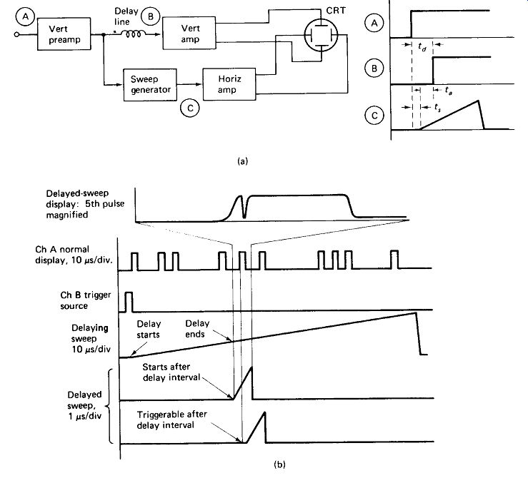
FIGURE 22-1 (a) A delay line in an oscilloscope allows the sweep to get started
before the triggering signal reaches the CRT, allowing the triggering signal
to be observed, (b) Delayed sweep allows tremendous expansion of complex wave
forms.
Sweep Magnification is used to expand a display horizontally, so the screen shows only a portion of the total sweep. The horizontal-position control is used to select the portion displayed. Magnification X 10 changes the 10 jus/division range to the 1 u-s/division range. Sweep magnification is helpful in displaying complex waveforms whose frequency components are hundreds of times higher than their repetition rates. Digital systems commonly produce such waveforms. The TV composite video signal provides another example.
Delayed Sweep is a more elaborate and more powerful solution to the problem of displaying complex waveforms. Let us say that a digital system generates 10 pulses at irregular times, as in Fig. 22-1(b), on a repetitive basis. A single pulse is also available at the start of each repetition. We wish to examine the fifth pulse more closely. We cannot do this by increasing the sweep speed because the trace would end before we got to the fifth pulse if we triggered on channel B, and the sweep would trigger on all 10 pulses making overlapping images if we triggered on channel A. Magnification would help, but magnification beyond 20 times often results in horizontal " jitter." The solution is to trigger a slow delaying sweep from channel B and set the sweep delay for a point just ahead of the fifth pulse. On modern scopes this is facilitated by an intensification of the trace at the delay point. The delayed sweep is set to a much faster rate and can be made to begin automatically at the delay point or to trigger from channel A after the delay point. The figure shows a 10:1 magnification of the fifth pulse, revealing a glitch on the leading edge that could not be seen with normal sweep. Actually, delayed sweep is more commonly used to provide magnifications on the order of 1000, sorting through hundreds of pulses rather than just ten.
Storage is a specialized and fairly expensive feature, used to preserve the display from a single-shot phenomenon. Contact bounce in a toggle switch and strain on a gun barrel when a bullet is fired provide two examples where a storage scope would be desirable. Single-sweep capability is a must in a storage scope. The stored image does not generally have the contrast or sharpness of a conventional display, and the writing rate limitation must be considered. A 50-cm/ms limit equals 1/50 ms/cm, or 20 u-s/cm. The stored image will not " take" at sweep rates faster than this. Storage CRTs are very expensive and have a limited life in the storage mode. Therefore, they should not be left in the storage mode unnecessarily.
Current Probes are clamp-on devices which use the current-carrying wire as the single-turn primary of a transformer. The secondary voltage is then proportional to the primary current. These passive or transformer-type probes respond to ac above 100 Hz or so only, and simply convert a scope's voltage scale into a current scale-10 mV/division into 100 mA/division, for example.
Active current probes which sense the magnetic field around a conductor and will respond to dc are available at a somewhat higher price.
Sampling Oscilloscopes are used to display signals with rise times below 1 ns and frequencies in the GHz range. Broadband amplifiers supplying CRT deflection-voltage levels to frequencies beyond 1 GHz are all but impossible, but fast-switching diodes at input signal levels are easily obtained. These diodes are switched to obtain a series of samples staggered on successive repetitions of the wave. The samples are then reconstructed into a low-frequency replica of the high-frequency wave which is easily handled by a conventional amplifier. The process is illustrated in Fig. 22-2. It can be seen that the nature of the sampling process precludes the display of single-shot phenomena.

FIGURE 22-2 Fast diodes are switched to obtain samples of a gigahertz wave
at successively later points on the cycle. The average of the samples is a
low-frequency wave that can be amplified and displayed easily.
22.2 OSCILLOSCOPE LIMITATIONS
Capacitive Loading: A standard X 10 scope probe has an input capacitance of 7 pF. This presents a reactance of 23 l at 1 GHz, 230 B at 100 MHz, 2.3 k ohm at 10 MHz, and so on. All it takes is money to buy a scope with a 500-MHz bandwidth, but it takes intelligence and skill to make any use of this bandwidth. Loading a 300-ohm source with 100 of capacitive reactance from a scope probe is obviously going to upset the voltage being measured.
Line Reflections: To make matters worse, a 2-m scope-probe cable is nearly a full wavelength long at 100 MHz, and there will be reflections and standing waves on the line unless it is fed by a Z0 source (probe end) and terminated in a Z„ load (scope end). This is almost never the case, so the scope displays the transformed sine-wave voltages and reflected pulses due to the mismatched line, rather than the true waveform at the test point before the probe was connected.
As a rule of thumb, then, the practical limit for conventional scope-probe measurements is about 20 MHz, unless the source is known to have an impedance below about 100 ohm and the probe cable is shorter than X.
50-ohm Environment: Accurate measurement of VHF signals is carried out entirely within what is termed a 50-ohm environment. This means that every output in the system has Rs = 50 ohm , every line is a coax cable with Z0 = 50 ohm, and the input to every amp, scope, meter, and so on, presents RL = 50 ohm. A meter is not connected directly across a line in such a system, but through a signal splitter, as illustrated in Fig. 22-3.
Bandwidth and Rise Time: A scope's bandwidth is the upper frequency at which a sine wave reads as 0.707 of its actual value. Reasonable accuracy cannot be expected unless the scope bandwidth is at least three times the frequency of the ...
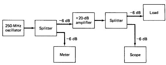
FIGURE 22-3 High-frequency Instruments are designed for 50-ohm inputs and 50-ohm
outputs. The meter and scope cannot simply be clipped across a line.
...signal being measured. If the signal is other than a sine wave, the scope must pass all important harmonics of the signal as well, so the scope will require a bandwidth 5 to 10 times the signal frequency.
For square and pulse waveforms, the scope's response speed is measured in terms of rise time, which is the time for the trace to rise from 10% to 90% of full value, given an input pulse with a rise time much faster than that of the scope. Rise time and bandwidth are related approximately by:
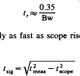
Where signal rise time is nearly as fast as scope rise time, we can compute signal rise time from

(22-2)
From this it can be seen that a scope rise time three times as fast as the signal rise time will result in a + 5% error in the measurement.
22.3 MULTIMETERS
The family of multimeters now includes, in historical order, the VOM (volt-ohm milliammeter), the VTVM (vacuum-tube voltmeter), its transistorized successor the TVM or FET meter, and the DVM (digital voltmeter). Of these, the VTVM was rendered obsolete by the FET meter, which has itself been all but eclipsed by the DVM. VOMs and DVMs have the following advantages over the oscilloscope:
. They are smaller, lighter, more rugged, and less expensive.
. They are easier to adjust and easier to read.
. They measure continuity and resistance, whereas a scope does not.
. They measure current (dc only for VOMs), which the scope will not do without an expensive special probe.
. They can generally be connected with both probes off ground, whereas the scope generally cannot. (Check your DVM and scope to see if the NEG or GND probe is connected to the chassis or ac-line ground.)
The VOM has an additional advantage over the DVM in continuity testing and tuning for peaks and nulls, in that the relative position of a meter pointer is easier to interpret than the flashing of a digital display. A few DVMs include pointer-type meters on their panels to recapture this convenience in taking quick readings.
The great advantage of the DVM is accuracy, which is commonly 1% to 0.1% on dc volts and 2% to 0.2% on ac, amperes, and ohms ranges, depending on DVM type and cost. This compares quite favorably with the 3%-of-full-scale accuracy which is typical of scopes and VOMs on the dc ranges.
Of course, the great disadvantage of VOMs and DVMs is that they respond strictly to average (on dc) or average absolute (on ac) values, without regard for waveform. A 5-V-dc level and a voltage rippling between 4V and 6V will each read 5V. A 2.83-V p-p sine wave and a 2.22 V p-p square wave will each read 1.00 V rms. Be wary of assuming that a dc multimeter reading is a sine wave. The main reason for preferring the oscilloscope to the multimeter where possible is that it leaves no such ambiguity.
Multimeters do not often have frequency-compensated attenuators, in which case their ac ranges may become totally inaccurate at frequencies as low as 500 Hz (3 pF has Xc = 10 MB at 500 Hz).
22.4 SIGNAL GENERATORS
Excepting for the moment some rather expensive special-purpose instruments, the field of signal generators is well represented by AF, RF, pulse, and function generators.
AF Generators most commonly use a Wien-bridge oscillator with some sort of automatic-gain-control circuit to avoid excessive feedback and consequent distortion. Tuning is accomplished by ganged variable capacitors or resistors, and square waves are produced by feeding the sine wave into a Schmitt trigger or saturated amplifier. Frequencies from 10 Hz to 1 MHz are commonly obtained in this manner.
RF Generators use an LC oscillator to produce signals from about 100 kHz to 100 MHz. Low-cost units seldom use automatic feedback control, so the output waveshape may be a badly distorted sine wave. Waveshape, amplitude, and output impedance may also change drastically with frequency setting. Provisions for modulating the amplitude or frequency of the output wave are generally made. If wide-band frequency modulation is possible (say, upper and lower limits of 60 MHz and 54 MHz) the instrument is called a sweep generator, and it can be used to display the frequency response curve for an amplifier, as shown in Fig. 22-4.
Such a setup is useful in aligning broadband amplifiers such as are found in TV receivers and FM radios.
V\M WW Frequency swept RF
Amplitude varying RF Sweep generator Tuned amplifier
Detector filter
Low-frequency sweeping signal .
Amplitude varying dc
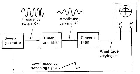
FIGURE 22-4 A sweep generator can be used to display the frequency response
curve of an amplifier on the scope.
Pulse Generators generally use an astable multivibrator to set pulse-repetition rate and a one-shot to set pulse duration. Output amplifiers are used to permit the output pulse to assume variable positive or negative values, mixed with a variable positive or negative dc offset, while maintaining rise and fall times of a few nanoseconds and a constant 50-ohm output impedance. More sophisticated pulse generators provide variable rise and fall times, pre-trigger output which provides a short spike about 1 u-s before the main pulse output, and double-pulse with variable spacing between the two pulse outputs.
Function Generators use an integrator and hysteresis switch to generate triangle and square waves and a shaping network to produce sine waves from the triangles.
Sine-wave purity is generally as good as or better than that of Wien Bridge oscillators. Frequencies below 0.001 Hz and above 10 MHz can. be produced with one instrument. Constant output amplitude and output impedance is assured. Even mid-priced units have dc offset and symmetry (duty-cycle) controls, offering many of the features of the basic pulse generator. Frequency modulation and frequency sweeping is possible via the VCO (voltage-controlled oscillator) input.
Amplitude-modulation capability and frequencies into the VHF range are not commonly available except in high-priced units.
22.S POWER SUPPLIES
A relatively large number of different power-supply types may be required fo development and prototype work, but only the first two in the following list are necessary for service work.
A Battery Eliminator delivers 6 to 15 V dc, roughly filtered and unregulated.
It i used to service mobile equipment and must furnish the necessary current, which may run 3 to 20 A, depending on the mobile equipment.
A Variable 60-Hz Autotransformer provides line voltages from 0 to 135 V.
It is used to simulate high and low line voltage conditions, since many malfunctions show up only under these extremes. Variable autotransformers are available with current limits from 1 to 10 A and more. Most line-operated equipment is designed to meet its specifications with line voltages between 105 and 125 V.
Voltages beyond this should be avoided.
A cheap-and-dirty substitute for a variable autotransformer is shown in Fig 22-5. It uses a 12.6-V center-tapped transformer to add or subtract 6.3 V or 12.6 V from the prevailing line voltage. The secondary current rating should equal the maximum anticipated load current.
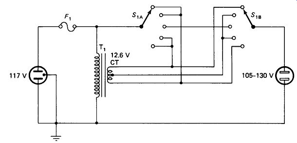
FIGURE 22-5 A 12-V center-tapped transformer can be used to construct high/low
line-voltage-test supply.
Low-Voltage Regulated Supplies are commonly used for solid-state development work. Two variable outputs each delivering 0 to 25 V with a maximum current of 0.5 to 2 A will be required, since op amps and many other circuits require balanced ± supplies. A separate + 5-V supply for logic ICs is also a great convenience, since this voltage is a widely accepted standard.
Current limiting is a desirable feature wherein the supply voltage drop whenever the load current rises above the set limit. This often prevents an accidental misconnection or a thermal avalanche in the prototype circuit from drawing destructive amounts of current.
Medium-Voltage Regulated Supplies are similar to the low-voltage supplies above, except that they cover the range to about 400 V with a maximum current of typically 300 mA.
High-voltage supplies cover the range to perhaps 20 kV.
22.6 MISCELLANEOUS INSTRUMENTS
The instruments covered so far in this section are considered basic to any service bench. This section will describe briefly a number of other instruments with fairly wide ranges of application. In addition, there are literally hundreds of other instruments useful only within a particular specialty (telephone, television, computer, biomedical, automotive, etc.). We will not have space to even mention all of these.
The Electrometer is simply a sensitive voltmeter with a nearly infinite input impedance.
The Vector Voltmeter is a rather complex instrument that measures the phase relationship between two signals as well as their amplitude. A dual-trace scope fills this function at frequencies below a few MHz, but vector voltmeters operate up to several gigahertz.
The Vector Impedance Meter is a variable frequency device with two meters, displaying impedance magnitude in ohms and phase in degrees. At low frequencies this information can be obtained by calculation from the voltages and phase angles measured with a dual-trace scope as shown in Fig. 22-6, but the vector Z meter is more accurate and convenient.
The RX Meter is a high-frequency impedance bridge with a built-in vari able-frequency oscillator.
The Q Meter provides much the same information as the RX meter, but uses a resonant circuit as shown in Fig. 22-7. An internal capacitor is tuned to resonate an external coil at the input frequency. A voltmeter reads the voltage rise across the capacitor, giving circuit Q. Capacitors are measured by using a standard coil and shunting the variable capacitor with the unknown capacitor. Frequency ranges from 50 kHz to 200 MHz are common for the foregoing two instruments.
Pen-Chart Recorders use a high-gain amplifier to drive a small servomotor which positions a pen on a strip of graph paper. The amplifier is fed by an input voltage and the chart is moved at a constant rate (several cm/day to several cm/s) by a ...
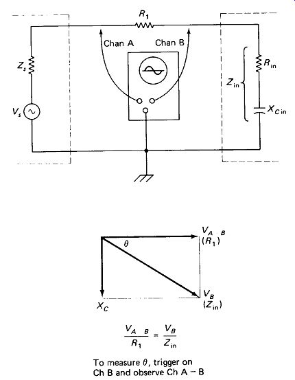
FIGURE 22-6 A differential-input scope can be used to obtain input impedance
and phase angle at low frequencies.
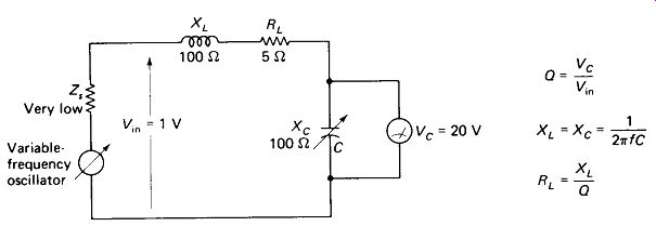
FIGURE 22-7
... fixed-speed motor and gear box. The pen-chart recorder thus functions as a very-low-sweep-rate oscilloscope.
X-Y Plotters contain two servo systems and can plot voltage against voltage.
Current and time scales are often included also.
The Gird-Dip Meter is now built with a transistor or tunnel diode, making the name a bit awkward, but the function is the same. An oscillator constructed with an external plug-in coil is tuned past the frequency of a separate tuned circuit whose resonant frequency is to be measured. The plug-in coil is held as near as possible to the coil of the separate tuned circuit, which will absorb energy from the oscillator when the two are tuned to the same frequency. This shows up as a dip in the oscillator current meter as the frequency is tuned past resonance.
Harmonic-Distortion Analyzers have been mentioned in Section 15. They measure the percentage of a voltage that consists of harmonics after the fundamental has been filtered out.
Wave Analyzers selectively tune in the fundamental and each harmonic to provide complete information on the Fourier spectrum of a signal.
Spectrum Analyzers use a sweep oscillator and a CRT display to literally give a picture of the Fourier spectrum of a signal, as in Fig. 15-2.
Intermodulation-Distortion Meters measure the distortion produced on one signal due to the presence of another. You will recall that two signals mixed in a nonlinear element will produce sum and difference frequencies by a process known as heterodyning. This should not occur in a linear amplifier, but an IM meter measures the extent to which it does occur.
Transistor Testers measure transistor beta and sometimes leakage (ICBO) and cutoff frequency (fT). Some measure , yfs of FETs as well. Some checkers simply look for current gain or signal inversion and give only a good-bad indication.
Curve Tracers, of course, display a complete set of characteristics (transistor of FET) on a CRT. Some curve tracers have a low-duty-cycle pulse mode which allows observation of the transistor at VI levels far above the steady-state maximum limits.
Digital Frequency Counters display the number of zero-line crossings of a voltage on a per second or total basis. For sine or square waves this is frequency in hertz, but for complex waves the display may be 2/ or 3/. The upper limit for most counters is 20 to 200 MHz or so. Their great advantage is accuracy, which is typically 5 parts per million (0.0005%). At low frequencies the period (time for one cycle) can be displayed. Some models will also display the ratio between two frequencies or the time between two events.
Logic Probes are small pen-like devices with an LED readout: red for logic high, green for logic low, yellow for forbidden voltage between high and low, and blinking for switching between high and low. Most probes are set for standard TTL-logic levels, although other levels are sometimes obtainable. A logic clip is actually 16 logic probes built into a single unit which can be clipped to a DIP IC pack to display all pin states at once.
Logic Pulsers supply very short pulses high and low, with the output in a high-impedance or floating state most of the time. The output peak current can thus approach 1 A, while the average current is less than 1 mA. The high peak currents force TTL totem-pole outputs high and low, regardless of what state they are " stuck " in. The driven stages can thus be checked without removing the driver.
The Current Tracer is a probe that senses the magnetic field around a conductor without encircling the conductor. The probe end can be placed on a PC conductor and the probe light will indicate if the track is carrying a switching current of 1 mA or more.
-----------------