Once a malfunction has been isolated to a certain section of an instrument, it becomes necessary to identify the individual faulty component. Checking components once they have been removed from the circuit is simple. The art of troubleshooting at this stage is to locate the defective component without tearing the circuit down to a pile of components.
23.1 SEMICONDUCTOR TESTING
Diodes: Silicon, germanium, Schottky, tunnel, and zener diodes should not have more than 1.1 V forward (positive at the anode) across them. Selenium diodes and HV silicon stacks (> 1 kV PRV) may show 10 or 20 times more, but anything in excess of this indicates an open diode, which should be removed, tested out of circuit, and replaced.
If it can be determined that a diode is carrying current (by a current probe or the voltage drop across a series resistance), but the diode drop is zero or only a few millivolts, the diode is probably shorted. Remove, test, and replace. A shorted power-supply diode may destroy the other diodes, the filter capacitor, and the power transformer, and these should be checked before applying full power.
Transistor In-Circuit Tests: Transistors showing more than 1.1 V base-to-emitter (positive base for NPN, negative base for PNP) have an open base-emitter junction and must be replaced. Transistors passing any of the following tests can be considered good and should be left alone. Failure to pass one of the tests does not necessarily mean that the transistor is bad, but failure to pass any of them is cause for suspicion.
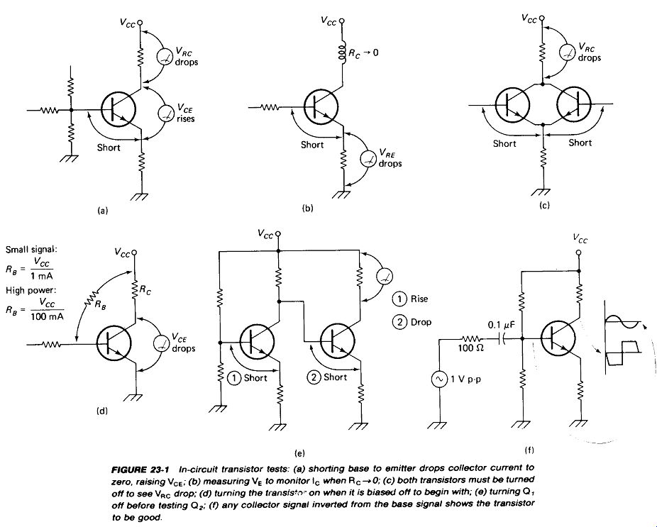
. Figure 23-1(a): Shorting the base to emitter should cause the collector voltage to rise to *cc and Vrc to drop to zero, unless the transistor is normally biased at cutoff.
. Figure 23-1(b): Where the collector load has near-zero resistance, the turnoff may be observed at the emitter resistor. Shorting B to E should cause Vre to drop, unless the transistor is normally biased at cutoff.
. Figure 23-1(c): Where two transistors appear in parallel, both must be turned off to observe the drop in VRC.
. Figure 23-1(d): Where a transistor is already biased off and Vc= Vcc, a resistor may be added from K:c to base to turn the transistor on. Calculate R to ensure that IB < 1 mA for small-signal and IB < 100 mA for power transistors. Adding RB should cause Vc to drop.
. Figure 23-1(e): Where the base is driven directly by a transistor, it may be necessary to turn the first transistor (Qx) off before the second (Q2) can be tested by methods (a) or (d).
. Figure 23-1(f): In an active transistor circuit, the collector signal appears inverted from the base signal. The base and collector waveforms can be examined on a dual-trace scope to verify this.
Disregarding signal levels and distortion, if the collector voltage drops when the base voltage rises, and vice versa, the transistor is basically functioning. It may have high leakage or low beta, but it is not completely dead. If no internally generated signal is present, a signal generator can be used to inject one at the base through 0.1 uF. The frequency may need to be varied widely to find an output signal if the collector circuit is frequency-dependent. If the collector is tied to Vcc or ground, it may not be possible to observe any signal there at all.
Transistor Out-of-Circuit Tests: If the in-circuit tests point to a defective transistor, it should be removed and tested out of circuit. A curve tracer is the ideal instrument for this job because it can spot low beta, high leakage, high saturation voltage, low collector breakdown voltage, and thermal instability as well as basic junction failure.
Fig. 23-1
Most transistors faults are simply shorts or opens of one of the junctions, however, and the simple VOM tests of Fig. 23-2 can be used to spot them. Use the R X 1 range for power transistors and the R X 100 or /? X 1 k ohm range for small-signal types. Determine with another voltmeter which probe of your VOM outputs a ...
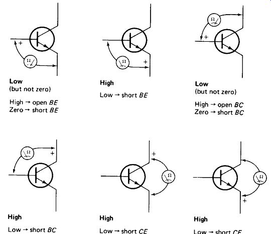
FIGURE 23-2 Out-of-circuit transistor-junction checks. Use a VOM on the R
x 100 or R x 1 K scale. Reverse polarities for PNP transistors.
... positive voltage on the ohms ranges and mark it. The tests shown in the figure are for NPN transistors. For PNP types simply reverse the meter probes in each case.
With a little practice, small-signal transistors with abnormally low beta or high leakage can be spotted with the VOM beta test shown in Fig. 23-3. The ohmmeter, on the R x 100 or X 1 k ohm range, is clipped between the collector and emitter (positive collector for NPN, positive emitter for PNP). The meter may deflect slightly, reading very high resistance. Large deflections indicate excessive I_CEO leakage. Now, without touching the emitter lead, grasp the collector lead with the fingers of one hand and the base lead with the other. The small current bled into the base will allow a large current from collector to emitter, and the meter will deflect greatly, showing low resistance. Small deflection indicates low beta.
FET Tests: Defective FETs can often be spotted in-circuit by the presence of abnormal gate voltage. The gate bias is usually obtained from a simple resistive network, and the expected voltage can be calculated easily, since Ic - 0 for a good FET. This is shown in Fig. 23-4(a). Don>t forget the loading effect of your meter.
Any large deviation from the expected VG indicates that gate current is flowing. If it is an insulated-gate FET, it is certainly bad in this case. If it is a junction FET, it
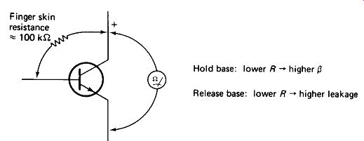
FIGURE 23-3 Ohmmeter beta and leakage test. Reverse polarities for PNP transistors.
may be bad, or it may be forward-biased gate-to-source. Check for 0.6-V forward Vgs- The phase-shift test of Fig. 23-1(f) can also be used.
Junction FETs can be tested out of circuit with an ohmmeter for diode action between gate and source (high R one way, low R the other way). With the gate shorted to the source, a channel resistance of a few hundred ohms should be measured drain to source, either polarity. These tests are not conclusive but will show up most defects.
Insulated-gate FETs can be checked for the substrate-to-source diode junction and for infinite gate-to-source resistance. Drain-to-source channel resistance (with the gate tied to the source) should range from a few hundred ohms for depletion types to infinity for enhancement types.
SCR Tests: A turned-on SCR should show 0.1 to 1.5 V or so positive anode-to cathode when conducting. Near-zero voltage indicates a shorted SCR. Vgk should never go above about 4- 1.2 V. If it does, suspect an open gate. Shorting the gate to cathode should keep the SCR from triggering, allowing positive voltage to appear from anode to cathode as in Fig. 23-4(b). If no positive voltage appears, suspect an open load or shorted SCR. Out of circuit an SCR should show a diode junction gate-to-cathode, and an open circuit to both polarities anode-to-cathode.
UJT Circuits usually fail to operate because the emitter voltage cannot reach the firing level or because the charging circuit supplies so much current that the UJT holds on once it fires. It is best to unsolder the emitter lead and measure Vc as shown in Fig. 23-4(c). If it does not rise to at least 0.85 VB2, check the charging circuit and C. Next connect a milliammeter from C to Bx. If the current exceeds the valley-current spec of the UJT, the charging circuit is supplying too much current, holding the UJT on.
Integrated Circuits contain, for the most part, transistors, diodes, and resistors which behave the same as their discrete-component counterparts. Do not be afraid to look into the schematic diagram of the internal circuit of an IC. Taken as a whole, it is usually quite formidable, but you can usually penetrate as far as the ...
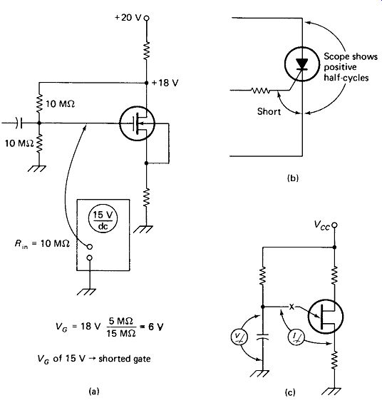
FIGURE 23-4 (a) Most bad FETs leak current from the channel to the gate, (b)
Shorting an SCR gate to cathode should keep It turned off. (c) Breaking a UJT
oscillator at the emitter allows measurement of maximum charging voltage and
hold-on current.
... base of the first transistor at the input and the collector of the last transistor at the output. This will give you some idea of what to expect and what is completely unreasonable at the input and output terminals.
23.2 CIRCUIT TRACING
Continuity Testing: A great number of problems can be located by checking out the simple expectation that a conductive path should have nearly zero resistance between its ends. A VOM on the R X 1 scale can be used for this, but an audible tester such as the one in Fig. 23-5 allows you to keep your eyes on the circuit. Use needle-point probes to pierce the insulative oxide layer that forms on many conductors, and be sure that the instrument power is off.
Fig. 23-5
When using a scope for troubleshooting with the power on, keep this in mind:
If two points in a circuit are connected by a conductor, they will measure the same voltage with respect to ground. If a case arises where two supposedly connected points show different voltages on the scope, you may be sure that the conductive path between them is broken. In this regard, remember that to a 10-ns pulse, 10 cm of wire is not a conductor, but a rather formidable inductor.
Following are some likely places to check for broken continuity:
. The two ends of a cable (broken center conductor or connector joint)
. The actual pin of an IC and the printed-circuit track leading to it (bad connection, especially if IC is in a socket)
. The two ends of a long thin printed-circuit track (broken conductor track or PC board)
. The fixed and moving contacts of a switch or relay (bent, broken, or corroded switch contacts) Shorts and Opens:
Figure 23-6(a) through (c) shows the voltage distribution in a series circuit under normal, short-circuit, and open-circuit conditions, respectively.
Notice that the short circuit throws added voltage to the remaining circuit elements, while depriving the shorted elements of any voltage at all. The open circuit deprives all of the circuit elements of voltage, since the entire source voltage appears across the break in the circuit.
To trace a series circuit for shorts or opens, we would start with the scope or voltmeter probe from ground to A, move it on to B, C, D, E, and F, noticing a certain drop in the voltage at each point until zero voltage is observed at F. If there is no voltage dropped across any of the elements until suddenly the entire voltage is dropped, you may be certain there is a break in the circuit [as between D and E in Fig. 23-6(c)].
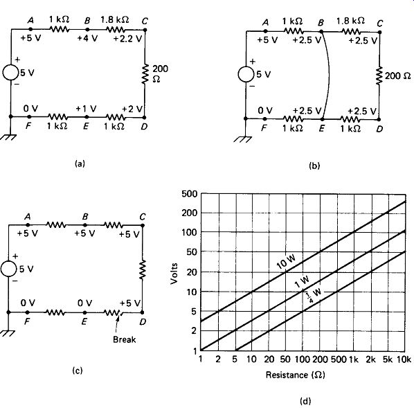
FIGURE 23-6 (a) Normal series circuit and voltages to ground, (b) Shorted
circuit shows no voltage across shorted elements, excessive voltage across
others, (c) Open circuit drops all voltage across the break, (d) Chart for
quick determination of resistor power.
If one or more elements are found with little or no voltage drop across them, we may be suspicious of a short circuit, but there may be several other reasons for it:
. Some elements have very low resistance under normal conditions. Fuses, thermistors, and coils may show very little voltage drop.
. Low value resistors will, of course, drop relatively little voltage, but values in the 100-ohm range are commonly used in series with input and output leads of high-frequency amplifiers to prevent vhf parasitic oscillations. These may show no drop at all at dc and signal frequencies. Power-supply decoupling resistors in the 100-0 to 1- k-Ohm range may also show almost no drop at dc.
. Certain resistors may drop almost no voltage under some signal conditions but show a substantial drop under other conditions. The emitter resistor in a class B push-pull or complementary-symmetry power amplifier will show almost no drop at idle, but may drop a volt or more at full signal. Schmitt triggers, one-shots, and flip-flops will show no drop across one collector resistor while dropping almost full Vcc across the other. RC snubbers used across SCRs and switched inductances will show no voltage across the resistor without switching action.
The chart of Fig. 23-6(d) shows the voltage that will produce a given power in a given resistance. Any resistor found to be dissipating more than its rated power should be suspected of being part of a shorted circuit. Power resistors (1 W or more) dissipating less than one-fourth of their rated power should be investigated for possible involvement in an open circuit.
23.3 TROUBLESHOOTING LOGIC
Often, it will be impossible to isolate a problem down to a single defective component by simply taking measurements on the circuit as it stands. Then it will be necessary to form some expectations of what should happen if the circuit is deliberately altered.
Exercise 1: Power-Supply Failure: Figure 23-7 shows a typical power-supply-input circuit. Let us say that it has blown a fuse. We observe by the black smear inside the fuse glass that its demise was quick and violent, rather than leisurely, so instead of consigning another fuse to the same fate, we connect a 115-V 150-W light bulb across the fuse holder. This will limit the input current to a little more than 1 A, even if the input is shorted. Upon measuring the primary of Tx we find only 1.
1 V_ac. The rest is dropped across the lamp. This could be caused by a short in C,, but it would then be carrying over 1 A at 1.1 V and would be getting quite warm. We feel it (power off first, please), find it at room temperature, and conclude that it is not shorted. We discount as too remote the possibility that R1 and /, both are shorted. That leaves Ty and T2.
T, is large (12 cm on a side) and has low enough internal resistance that a short at its secondary could reflect as nearly a short at its primary. T2 is small, (5 cm on a side) and its winding resistance would prevent a secondary short from reflecting back such a low resistance to the primary. The problem could then be due to:
1. r, primary short
2. Tx secondary short
3. D6 short
4. D, and beyond short
5. T2 primary short.
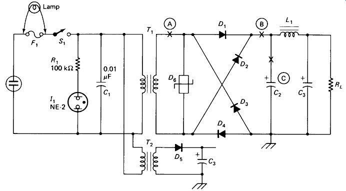
FIGURE 23-7 Power-supply troubleshooting exercise. (See the text.) To eliminate
among these five possibilities, we decide to split them approximately in half
by unsoldering the T, secondary lead at A. This causes the 150-W lamp to go
dim and we now measure 115 V at the Tx primary. T1 and T2 are obviously good,
so the problem lies in £>6 or Z), and beyond.
Next we move the thyrector D6 lead to the left of the break at A and notice that the lamp remains dim. That means that D6 is good. Hoping the diodes are good but C2 or the load is shorted, we break the circuit at B. Applying power, we see the lamp light again. At least one diode is bad. We unsolder one end of each diode and test it with an ohmmeter. Two are shorted and one is open. We replace them.
Mindful that C2, C3, or the load may be shorted, we replace the 150-W lamp at Fl with a 25-W lamp to avoid blowing out our new diode, reconnect A and B, and again apply power. The 25-W lamp lights and we measure zero voltage from point B to ground. C2, C3, or the load must be shorted.
We disconnect C2 at point C1 short it for a moment from force of a well-ingrained habit, and test it with an ohmmeter. Shorted! Replacing C2, the 25-W lamp glows more dimly, leaving 50 V across Tlt so we graduate to the 150-W lamp. Things still look good, so we replace the fuse and let the instrument cook for a while before returning it to service.
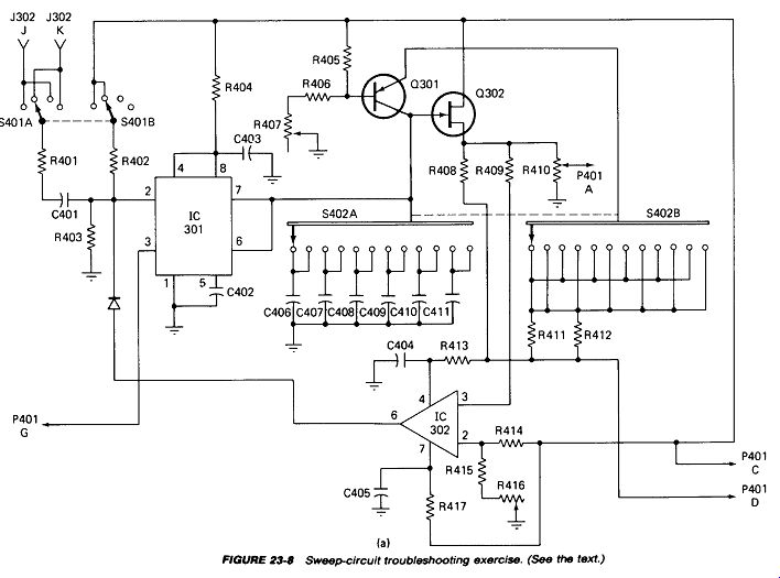
FIGURE 23-8
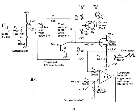
FIGURE 23-8 (Continued).
Exercise 2: Sweep-Generator Failure: Figure 23-8(a) shows a sweep generator from a special-purpose oscilloscope. The output voltage hangs at +1 V dc, but cannot be made to produce ramps.
A serious problem is that the schematic seems to have been prepared for purposes of component inventory rather than servicing. Little progress will be made in troubleshooting until the functional relationships in this circuit are clarified. The technician should not hesitate to modify and annotate a copy of the schematic, or even to redraw it in simplified form if that will make its function more clear.
Figure 23-8(b) shows a more usable schematic with voltage measurements included and range-switching and decoupling components omitted. The circuit operation is now clear: C, couples the edges of the square wave to the trigger input of the 555, bringing it below + 3 V on the negative edges. This causes the discharge transistor to turn off, and current source Qx charges C2 at a linear rate. The source of Q2 follows this ramp, offset by about + 1.25 V.
As long as the source of Q2 is above +1.3 V, op-amp comparator IC2 holds the 555 trigger input positive forcibly via Dx, so no more negative spikes are allowed to the trigger input. Once the ramp at pin 6 of the 555 reaches 6 V, pin 7 discharges C2 rapidly, and the FET source brings pin 3 of IC2 below pin 2. The comparator output then goes negative, turning off £>, and allowing C, to deliver another negative pulse to the trigger input.
A 60-Hz square wave is available at the input, but a scope check at pin 2 of /C, reveals neither positive nor negative spikes. This is not surprising, since the time constant of C, with Rt, R2, and R3 is 1 us and the pulse rate is one every 16,700 u-s.
A check of the 318 op-amp specs shows that the output current is limited to about 20 mA and the output can be short-circuited indefinitely, so we feel safe in shorting trigger pin 2 of the 555 to ground for an instant. A single linear ramp of about 4 V pk is seen on the scope at the output each time this is done. Apparently, everything works except that the 555 is not receiving trigger pulses.
A scope probe at pin 6 of IC2 shows + 8 V dc, even when the 555 is artificially triggered. Either IC2 is bad or it is not being fed the proper inputs. Output pin 6 should go negative if input pin 3 goes below pin 2. Not wishing to upset a calibration setting, we leave trimpot R1 , alone for a while and short pin 3 to ground. Pin 6 goes negative and ramps appear at the output.
Convinced that the Q2 source voltage was simply too high for the setting of R1 ,, we readjust Ru and proper operation is restored. However, realizing that the malfunction must have been caused by a change in some circuit parameter, we spray clean the wiper of and change Q2 and IC2. The $2 component cost is considered a small price to pay for insurance against future failures, which would certainly occur if one of these semiconductors were undergoing parameter changes due to loss of its hermetic seal.
23.4 INTERMITTENT TROUBLES
The most exasperating troubles are the intermittents: bad in the field but working perfectly once you get them on the service bench. Here are some tips for locating intermittents more efficiently:
Check It in the Field: If the problem is intermittent, don't just pick up the instrument and take it back to the bench. If possible, have the operator call you when the trouble is present and let him show it to you. You may find that he isn’t using the instrument properly or you may see that he has been abusing it, thereby causing the problem.
If the problem is present, flex all the wires and connectors and tap the control knobs and switch handles while observing the instrument’s operation. These externals are most likely to have suffered abuse, and you may be able to locate the trouble or at least narrow it down right in the field.
Try to Induce the Trouble: Once the instrument is on the bench, try to get the malfunction to show up. Removing the cabinet often provides enough ventilation to keep temperature-related problems from occurring, so it is a good idea to use a heat lamp to warm the suspected area of the circuit board. Be careful not to melt any plastic parts.
Aerosol cans containing a spray coolant are readily available and are excellent for locating temperature-sensitive components. The instrument is warmed up until the intermittent problem appears; then each component in the malfunctioning area is sprayed with the coolant until one is found that restores proper operation when cooled. Integrated circuits, transistors, and capacitors are the most likely components to check. Avoid getting the coolant on the hot glass of vacuum tubes or lamps by using a sheet of stiff paper as a shield.
If the trouble cannot be induced by heating or cooling, try high and low line voltages (105 to 130 V) using a variable autotransformer. Let the instrument rest at each extreme for several minutes.
Some problems that appear to be intermittent defects are actually interference from electric motors, CB radios, pocket calculators, and so on.
If the intermittent will not reoccur, tag the instrument in an inconspicuous place, giving the date and nature of complaint, before returning it to service. If it appears again with the same complaint, the tag will at least confirm the validity of the complaint, and you may be able to deduce from the conditions under which it malfunctioned what the causes of the trouble might be. Perhaps both failures occurred under high altitude, or high humidity, or under the same operator.
23.S CABLE FAULTS
Cables are often flexed, stretched, trampled upon, and subjected to sun, rain, and ice. Small wonder, then, that they are frequently the cause of system malfunctions.
Broken End Connections are very common in test leads and instrument probes.
The simple ohmmeter tests of Fig. 23-9(a) will verify shorts and opens, and flexing of the cable and connectors may produce an intermittent connection which will identify the location of the flaw. Often, however, the ohmmeter will reveal that the center conductor is broken, but leave unanswered the question: "At which end?" To avoid removing both end. connectors, the test setup of Fig. 23-9(b) can be employed. A break at the far end of the cable will result in several volts of line-noise pickup on the scope, whereas a break at the scope end will give only a few millivolts of noise pickup.
Breaks in Underground Cables can be located quite accurately by measuring the capacitance between two cable conductors with a capacitance bridge, as shown in Fig. 23-10(a). If a check of a sample of the cable shows the conductors to have a capacitance of 43 pF/m and the buried cable measures 0.028 uF at the point of ...
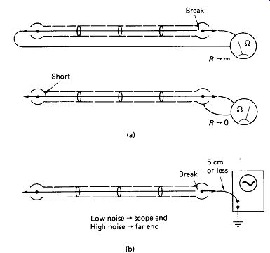
FIGURE 23-9 (a) Ohmmeter checks for cable shorts and opens, (b) Noise-pickup
test to determine which end of the cable contains the break.
... origin, we may expect to find the break if we dig 0.028 n F/43 pF/m or 651 m from the point of origin. Better accuracy might be obtained if the capacitance of a wire pair between two access points were measured before a break occurred and the capacitance per unit length calculated and recorded from these data. Pressure and stray capacitance from the packed earth may introduce errors if the capacitance per meter is taken from a short cable sample in air.
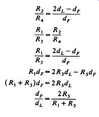
Shorts in Underground Cables or insulation breakdowns can be located by means of the Murray Loop test shown in Fig. 23-10(b). The setup actually comprises an elementary Wheatstone bridge, with legs R2 and R4 consisting of lengths of conductor in the cable. A second conductor, intact but otherwise identical to the faulted conductor, must be available and must be connected to the faulted conductor at the far-access point as shown. The ratio of resistance R4 (to the fault) to R2 (out the good conductor and back to the fault) is determined by the bridge, and an equation is developed relating the distance to the fault dF to the distance between access points dL:

(23-1)
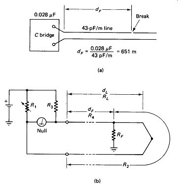
FIGURE 23-10 (a) Determining the distance to an underground break by inter-conductor
capacitance, (b) Murray loop test to determine distance to an underground short.
The derivation of this formula makes use of the Wheatstone-bridge-balance equation and the assumption that resistance is proportional to length for the buried conductors.
--------------
If the fault is a short to another conductor in the cable rather than to ground, the negative side of the battery is connected to this other conductor. If the fault is resistive rather than a dead short, RF simply appears in series with the battery and does not enter into the calculations. If a second conductor identical to the first is not available, it may be worth the trouble to string a temporary one above ground, since the only other alternative might be to dig up the entire length. As a check, it would be wise to repeat the test with the short at the left access point and the bridge at the right access point.
Cable Deterioration is a serious problem, especially with high-frequency coaxial cable. Deterioration is evidenced by characteristic impedance changes and consequent reflected signals, and by dielectric absorption, evidenced by excessive signal attenuation at high frequencies (say, above 100 MHz). Cable life can be extended greatly by proper installation. Here are some tips:
. Support in-air runs from plastic-coated steel wire. Don , t let the cable carry its own weight.
. Keep the cable out of the sun if possible, but if it must be in the sun, keep it in free air to avoid heat buildup and standing water.
. Do not expose connector ends or splices to rain or standing water. Keep splices and connectors higher than the cable runs so condensation will run away from-not toward-the break in the cable jacket. Build a bird house-size cover over splices if they must be made in the open.
. The smallest break in a cable jacket will soak up water like a sponge if given the chance. Capillary action will send this water far along the inside of the cable, ruining great lengths of it. Tape is completely useless in sealing breaks. It may last a week or a month, but can never be considered permanent. Most paint-on dopes and sealers are also of dubious reliability.
Heat-sinkable tubing properly applied offers the best chance, but keeping breaks out of the weather is the real solution.
-----------------